Language selection

Search

Patent 2317277 Summary

Third-party information liability

Some of the information on this Web page has been provided by external sources. The Government of Canada is not responsible for the accuracy, reliability or currency of the information supplied by external sources. Users wishing to rely upon this information should consult directly with the source of the information. Content provided by external sources is not subject to official languages, privacy and accessibility requirements.

Claims and Abstract availability

Any discrepancies in the text and image of the Claims and Abstract are due to differing posting times. Text of the Claims and Abstract are posted:

  • At the time the application is open to public inspection;
  • At the time of issue of the patent (grant).
(12) Patent Application: (11) CA 2317277
(54) English Title: STEAM BOX
(54) French Title: PRECHAUFFEUR
Status: Deemed Abandoned and Beyond the Period of Reinstatement - Pending Response to Notice of Disregarded Communication
Bibliographic Data
(51) International Patent Classification (IPC):
  • D21F 05/00 (2006.01)
  • D21F 07/00 (2006.01)
(72) Inventors :
  • ALEN, JUKKA PEKKA (Finland)
  • HASSINEN, REIJO (Finland)
  • HARKONEN, TAPIO (Finland)
  • LUOSMA, TOMMI (Finland)
  • NAATANEN, TUOMAS (Finland)
  • SAMPPALA, JUKKA (Finland)
(73) Owners :
  • METSO PAPER AUTOMATION OY
(71) Applicants :
  • METSO PAPER AUTOMATION OY (Finland)
(74) Agent: GOWLING WLG (CANADA) LLP
(74) Associate agent:
(45) Issued:
(22) Filed Date: 2000-08-30
(41) Open to Public Inspection: 2001-03-06
Availability of licence: N/A
Dedicated to the Public: N/A
(25) Language of filing: English

Patent Cooperation Treaty (PCT): No

(30) Application Priority Data:
Application No. Country/Territory Date
U990372 (Finland) 1999-09-06

Abstracts

English Abstract


The invention relates to a steam box (10), which includes a
elongated steam-distribution chamber (11), regulator chambers
(15) set in a row next to this and covered on one side with a
continuous perforated screen (20), and operating devices (13) to
distribute the steam from the distribution chamber to each
regulator chamber (15). The steam box (10) is intended to feed
steam through the perforated screen (20) to the web, to heat it
according to the desired profile. The aforesaid perforated screen
(20) is secured along one long edge to hinge members (21) and
along the opposite .edge to locking members (22) and is arranged
to be able to be opened, to permit access to the regulator
chambers (15).


Claims

Note: Claims are shown in the official language in which they were submitted.

5
Claims
1. A steam box (10), which includes a elongated steam-distribution
chamber (11), regulator chambers (15) set in a row next to
this and covered on one side with a continuous perforated
screen (20), and operating devices (13) to distribute the steam
from the distribution chamber to each regulator chamber (15),
and which steam box (10) is intended to feed steam through the
perforated screen (20) to the web, to heat it according to the
desired profile, characterized in that the aforesaid perforated
plate (20) is secured along one long edge to hinge members (21)
and along the opposite side to a locking member (22) and that
it is arranged so that it can be opened to permit access to the
regulator chambers (15).
2. A steam box (10) according to Claim 1, characterized in that
the regulator chambers (15) are formed in a unified elongated
space by separating them from one another by means of partition
walls (15'), and the perforated screen (20) is arranged to
press directly against these partition walls (15').
3. A steam box (10) according to Claim 1 or 2, characterized in
that the steam box also includes a unified auxiliary distribution
chamber (16) on the other side of the distribution chamber
(11) equipped with another heat-distributing perforated screen
(18) and in which the distribution chamber (11) and the
auxiliary distribution chamber (16) are covered with a unified
plate, the aforesaid other perforated screen (18) being part of
this unified plate (19).
4. A steam box (10) according to Claim 1 or 2, characterized in
that the hinge members (21) are installed on the outer edge
side of the regulator chambers (15) and the locking members
(21) on the distribution chamber (11) side.

6
5. A steam box (10) according to Claim 4, characterized in that
the locking members (22) comprise an axle (23) secured
rotatably to the inside of the free edge of the perforated
screen (20), with indentations (26) formed at regular intervals
along it, and stops (28) extending to the axle (23) and set at
corresponding intervals along the edge (15.1) of the regulator
chambers, and in which the axle (23) is arranged to be able to
pass the stops (28) at those stops (28) that are in the
indentations (26) and to lock against the stops (28) that have
been turned to the bottom (27) of the indentations (26).
6. A steam box (10) according to Claim 1 or 2, characterized in
that the entire web-side edge of the steam box is arranged to
be opened as one or more parts, with each part being secured to
the aforesaid hinge members along one long edge of the steam
box, the locking members being on the opposite edge.

Description

Note: Descriptions are shown in the official language in which they were submitted.


CA 02317277 2000-08-30
1
STEAM BOX
The present invention relates to a steam box, which includes an
elongated steam-distribution chamber, regulator chambers set in
s a row next to this and covered on one side with a continuous
perforated screen, and operating devices to distribute the
steam from the distribution chamber to each regulator chamber,
and which steam box is intended to feed steam through the
perforated screen to the web, to heat it according to the
io desired profile.
US publication 5,711,087 (Pazdera) discloses a heating device
for heating a web. Steam or hot air is fed to the web from a
elongated chamber through a perforated screen conforming to the
i5 shape of the web. The screen easily dirties in use and must be
cleaned. To facilitate this cleaning, the perforated screen is
arranged to be detachable, in such a way that both of its long
sides are attached to the frame of the apparatus by means of
clip members.
The width of the regulator chambers of modern profiling steam
boxes can be as little as 60 mm, which permits a precise
heating profile over the width of the web. A relatively common
construction is one, in which each regulator chamber is
2s equipped with a condensation water removal muff pipe, through
which the water flows to the casing space, from which it is
removed separately. One end of the muff is normally closed with
a plug, but during maintenance the plug is removed, opening the
condensing water channel through the muff. This is quite
labourious, while it is impossible to gain access to the whole
regulator chamber. Naturally, the perforated screen (diffusion
plate) can be cleaned from outside using a water jet, but even
this operation will carry fibres into the regulator chambers.
The construction in the aforesaid US publication permits easy
access to the regulator chambers, but the removal and installa-

CA 02317277 2000-08-30
2
tion of the perforated screen has turned out to be difficult.
Its length corresponds essentially to the width of the web,
making it quite heavy to handle.
s The present invention is intended to create a steam box,
according to the preamble, which can be cleaned more easily
than previously. The characteristic features of a steam box
according to the invention appear in the accompanying Claims.
The perforated screen, i.e. diffusion plate, which is supported
io on hinges, can be in one or more parts, together covering the
entire width of the web. The hinges permit the screen to be
opened safely and lightly by one person.
Other advantages and embodiments of the invention will become
is apparent in connection with the example described, which is
shown in the accompanying figures.
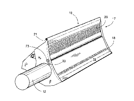
Figure 1 shows an axonometric view of a steam box according to
the invention
2o Figure 2 shows a cross-section of the steam box of Figure 1
Figure 3 shows the locking mechanism in detail
Figure 4 shows the locking mechanism in the open position
Steam box 10 is set against a roll. The end-plates and long
2s sides conform closely to the surface of the roll, allowing very
little steam to escape. On the front side, in the direction of
travel of the web, are regulator zones 17, by means of which
the desired heating profile can be formed over the width of the
web. On the exit side, there is a constant zone 18, through
ao which an even flow of steam is directed to the web over its
entire width. Hot steam is led through pipe 12' to the steam
box, 90 % typically going to the regulator zones and 10 o to
the constant zone.
35 The regulator zones 17 are formed of regulator chambers 15, on
top of which there is a continuous perforated screen 20, which

CA 02317277 2000-08-30
3
can be raised around hinge members 21. Perforated screen 20 is
locked into its operating position, by means of a mechanism to
be disclosed later and operated by handle 32. In this steam
box, only the cover of the regulator zone, i.e. perforated
screen 20, can be opened. If necessary, the second part of the
front surface 19 can be arranged to open in the same way, or
the entire front surface can be formed into a unified cover,
covering both the regulator zones and the constant zone.
to Figure 2 shows the construction of the steam box. Steam is led
through pipe connection 12 to the distribution chamber 11 in
the centre. On the front side of distribution chamber 11 are
regulator chambers 15, which are formed by dividing a common
elongated space into sections by means of partition walls 15'.
i5 Constant chamber 16, which here is fed through connection 16.1,
is on the other side of distribution chamber 1. Water condens-
ing in the chambers is collected in casing 29 and condensing
water removal channels 31. The rear part 10 of the steam box
acts as a stiffener and attachment frame.
Steam is distributed to the regulator chambers with the aid of
regulators 13 and the condensed water is removed from each
regulator chamber 15 with the aid of removal connection 30. As
blockage of this removal connection 30 would prevent the
2s regulator chamber from functioning, the chambers are cleaned 1
- 2 times a year. To facilitate cleaning, the diffusion plate,
i.e. perforated screen 20, can be opened around hinge members
21, once the locking members 22 have been opened, Figure 2.
Perforated screen 20 (perforation next to the regulator
3o chambers) is bent at the edge and conforms to the shape of the
partition walls 15' or the regulator chambers, making the
chambers steam-tight when perforated screen 20 is closed.
The broken lines in Figure 2 show perforated screen 20 in the
35 open position, when there is unrestricted access to regulator
chambers 15. For various reasons, the width of the web at

CA 02317277 2000-08-30
4
perforated screen 20 can be divided into two or more parts.
Thus, a steam box for a web with a width of 10 metres, can have
two 5-metre wide perforated screens 20.
s Figures 3 and 4 show details of the operation of the locking
mechanism. Axle 23 is secured rotatably to the edge 25 of
perforated screen 20 by means of clamps 24 and is operated by
handle 30. At regular intervals (0,5 - 1 m) along axle 23,
there are segmentally-shaped indentations 26. Their bottom
io surface 27 forms a locking surface against pins 28 secured to
the edge 15.1 of the regulator chamber. Each pin 28 extends,
according to Figure 5, inside the axle, but not as far as the
bottom surface, when indentation 26 is turned against it. Thus,
according to Figure 5, perforated screen 20 can be raised or
i5 lowered past each pin. In the closed position, axle 23 is
rotated, so that the bottom surface 27 of each indentation 26
presses against pin 28.
The bottom surfaces 27 of the indentations 28 are phased, so
2o that each locking pin 28 applies an equally great moment.

Representative Drawing
A single figure which represents the drawing illustrating the invention.
Administrative Status

2024-08-01:As part of the Next Generation Patents (NGP) transition, the Canadian Patents Database (CPD) now contains a more detailed Event History, which replicates the Event Log of our new back-office solution.

Please note that "Inactive:" events refers to events no longer in use in our new back-office solution.

For a clearer understanding of the status of the application/patent presented on this page, the site Disclaimer , as well as the definitions for Patent , Event History , Maintenance Fee  and Payment History  should be consulted.

Event History

Description Date
Inactive: IPC from MCD 2006-03-12
Application Not Reinstated by Deadline 2004-08-30
Time Limit for Reversal Expired 2004-08-30
Deemed Abandoned - Failure to Respond to Maintenance Fee Notice 2003-09-02
Letter Sent 2001-11-27
Inactive: Single transfer 2001-10-23
Application Published (Open to Public Inspection) 2001-03-06
Inactive: Cover page published 2001-03-05
Inactive: First IPC assigned 2000-10-12
Letter Sent 2000-09-21
Inactive: Filing certificate - No RFE (English) 2000-09-21
Application Received - Regular National 2000-09-20

Abandonment History

Abandonment Date Reason Reinstatement Date
2003-09-02

Maintenance Fee

The last payment was received on 2002-07-15

Note : If the full payment has not been received on or before the date indicated, a further fee may be required which may be one of the following

  • the reinstatement fee;
  • the late payment fee; or
  • additional fee to reverse deemed expiry.

Patent fees are adjusted on the 1st of January every year. The amounts above are the current amounts if received by December 31 of the current year.
Please refer to the CIPO Patent Fees web page to see all current fee amounts.

Fee History

Fee Type Anniversary Year Due Date Paid Date
Application fee - standard 2000-08-30
Registration of a document 2000-08-30
Registration of a document 2001-10-23
MF (application, 2nd anniv.) - standard 02 2002-08-30 2002-07-15
Owners on Record

Note: Records showing the ownership history in alphabetical order.

Current Owners on Record
METSO PAPER AUTOMATION OY
Past Owners on Record
JUKKA PEKKA ALEN
JUKKA SAMPPALA
REIJO HASSINEN
TAPIO HARKONEN
TOMMI LUOSMA
TUOMAS NAATANEN
Past Owners that do not appear in the "Owners on Record" listing will appear in other documentation within the application.
Documents

To view selected files, please enter reCAPTCHA code :


To view images, click a link in the Document Description column. To download the documents, select one or more checkboxes in the first column and then click the "Download Selected in PDF format (Zip Archive)" or the "Download Selected as Single PDF" button.

List of published and non-published patent-specific documents on the CPD .

If you have any difficulty accessing content, you can call the Client Service Centre at 1-866-997-1936 or send them an e-mail at CIPO Client Service Centre.


Document
Description 
Date
(yyyy-mm-dd) 
Number of pages   Size of Image (KB) 
Representative drawing 2001-02-26 1 19
Abstract 2000-08-29 1 21
Description 2000-08-29 4 175
Claims 2000-08-29 2 71
Drawings 2000-08-29 3 84
Courtesy - Certificate of registration (related document(s)) 2000-09-20 1 120
Filing Certificate (English) 2000-09-20 1 163
Courtesy - Certificate of registration (related document(s)) 2001-11-26 1 113
Reminder of maintenance fee due 2002-04-30 1 111
Courtesy - Abandonment Letter (Maintenance Fee) 2003-10-27 1 176