Note: Descriptions are shown in the official language in which they were submitted.
CA 02317872 2007-07-09
SIDE MOUNTED TEMPERATURE PROBES FOR PRESSWAR)E: DIE SETS
s
Technical Field
The present invention relates to the temperatvre-controlled die sets for
forming food serving disposable pressware containers, such as plates, bowls,
trays
and the like, and more particularly to a temperature controlled die set
utilizing a side
mounted, flexible temperature probe which is angled toward the forming surface
of a
die segment. The apparatus of the present invcntion is particularly uscfi2l
for formuig
plates and the like from paperboard blanks, where temperature control near the
forming surfaces is pazticularly importanl.
Background
Pressed contai.ners, such as pressed paperboard containers inClucling plates,
trays, bowls and the like aze well known in the art. Typically, such articles
are
manufactured on an inclined die set having upper and lower halves.
Ilhistrative in
this regard is United States Patent No. 5,249,946 to Marx assigned to the
assignee of
the present invention_ Referting to the '946 patent, a typicul product is
ananufactured
by way of feeding a continuous paperboard web into a cyclically operating
blanldng
section. The forming section includes a plurality of reciprocating upper die
halves
opposing; in facing relationship, a plurality of lower die halves. Thc upper
die halves
are mounted for reciprocating movement in a direction that is oblique or
inclined
with respect to the vertical plane. The blanks, after cutting, are gravity fed
to the
inclined lower die halves in the forming section.
CA 02317872 2007-07-09
2
ParticLilar forming dies and processes for making pressed paperboard products
are likewise well known. Most typically, -die sets for forming paperboard
containers
include a male or punch die half and a female die half. Typically, the punch
half is
reciprocally mounted with respect to its opposing die half and both die
hal.ves are
segrnented_ One or rnorc porrions of the die halves may be spring-biased if so
desired, and the particular geometry of the die will depend upon the product
desired.
In this regard, there is shown in United States Patent No. 4,832,676 to Johns
et a1. an
apparatus for forming a compartmented paperboard plate. The dies illustiated
in the
`676 patent includes spring-biased segments as well as pressurc rings on the
punch
half and draw rings about the opposing plate. The particular apparatus
)iu'ther
includes an articulated, full area knock-out.
Formitlg operations can be somewhat critical in order to p.roduce quality
product at the desired rates. In this respect United States Patent No.
4,721,500 to Van
Handle er al. is informative. Note also United States Patent No. 4,609,140 to
Van
Handle et al. The `140 patent provides a generaI description of one known
forming
method as will be appreciated from Figure3 thereof. Figure 3 shows a._ross
section
of the upper die half and lower die balf which are utilized to press a flat,
circular
paperboard blank into the shape of the plate. The construction of the die
halves and
the equipment on which they are mounted is substantially conventional; for
example,
as utitized on presses manufactured by the Peerless Maniifacturing Company. To
facilitate the holding and shaping of the blank, the die halves are segmented
in the
manner shown. The lower die has a circular base portion and a cent<al circular
platform which is mounted to be moveable with respect to the base. Tht
platform is
cam operated in a conventional manner and urged toward a normal position such
that
its flat top forming surface is initially above the forming surface of the
base. The
platform is mounted for sliding movement to the base, with the entire base
itself
being mounted in a conventional manner on springs. Because the blank is very
tightly pressed at the peripheral rim area, moisture in the paperboard which
is driven
CA 02317872 2007-07-09
3
therefrom during pressing in the heated dies cannot readily escape. To allow
the
release of this moisture, at least one circular groove is provided in the
surface of the
base which vents to the atmosphere through a passageway. Similarly, the top
die half
is segmented into an outer ring portion, a base portion and a central platform
having a
flat forming surface. The base portion has curved, symrrietrical forming
surfaces and
the outer ring has curved forming surfaces. The central platform in the outer
ring is
slidingly mounted to the base and biased by springs to their normal position
shown in
Figure 3 in a commercially conventional manner. The top die half is mounted to
reciprocate toward and away from the lower die half. In the pressing
ope:ration, the
1 o blank is first laid upon the flat forming surface, generatly underlying
the bottom wall
portion of the plate to be formed, and the forming surface makes first contact
with the
top of the blank to hold the blank in place as the forming operation begi;zs.
Further
downward movement of the top die half brings the spring-biased forming
surfaces of
the outer ring into contact with the edges of the blFUZk to begin to shape the
edgcs of
the blank over the underlying surfaces in the areas which will define the
overtumed
rim of the fnished plate. However, because the ring is spring-biased the;
paperboard
material in the rim area is not substantially compressed or distorted by the
initial
shaping since the force applied by the forming surfaces is generally light and
limited
to the spring force applied to the ring. Eventually, the top die half moves
sufficiently
far down so that the platform segments and the ring are fully compressed such
that
the adjacent portions of the forming surfaces are coplanar. In a conventional
manner
the die halves are heated with electrical resistance heaters and the
temperature of the
die halves is controlled to a selected level by monitoring the temperature of
the dies
with thermistors mounted in the dies as close as possible to the fomiing
surfaces.
For paperboard plates stock of conventional thicknesses ie. in the range of
from about 0.0 10 to about 0.040 inches, the spacing between the upper dze
surface
and the lower die surface declines continuously from the nominal paperboard
thickness at the center to a lower value at the rim.
CA 02317872 2000-11-24
4
The springs upon which the lower die half is mounted are typically
constructed such that the full stroke of the upper die results in a force
applied between
the dies of from about 6000 to 8000 pounds.
The paperboard which is formed into the blanks is conventionally produced
by a wet laid paper making process and is typically available in the form of a
continuous web on a roll. The paperboard stock is preferred to have a basis
weight in
the range of from about 100 pounds to about 400 pounds per 3000 square foot
ream
] o and a thickness or caliper in the range of from about 0.010 to about 0.040
inches as
noted above. Lower basis weights and caliper paperboard is preferred for ease
of
forming and for saving feedstock costs. Paperboard stock utilized for forming
paper
plates is typically formed from bleached pulp furnish, and is usually double
clay
coated on one side. Such paperboard stock commonly has a moisture (water
content)
varying from about 4.0 to about 8.0 percent by weight.
The effect of the compressive forces at the rim is greatest when the proper
moisture conditions are maintained within the paperboard: at least 8% and less
than
12% water by weight, and preferably 9.5 to 10.50.'o. Paperboard in this range
has
sufficient moisture to deform under pressure, but not such excessive moisture
that
water vapor interferes with the forming operation or that the paperboard is
too weak
to withstand the high compressive forces applied, To achieve the desired
moisture
levels within the paperboard stock as it comes off the roll, the paperboard is
treated
by spraying or rolling on a moistening solution, primarily water, although
other
components such as lubricants may be added. The moisture content may be
monitored with a hand held capacitive type moisture meter to verify that the
desired
moisture conditions are being maintained. It is preferred that the plate stock
not be
formed for at least six hours after moistening to allow the moisture within
the
paperboard to reach equilibrium.
CA 02317872 2007-07-09
S
Because of the intended end use of the paper plates, the paperboard stock is
typically coated on one side with a liquid proof layer or layers. In addition,
for
esthetic reasons, the paper plate stock is often initially printed before
being coated. As
an example of typical coating material, a first layer of polyvinyl acetate
emulsion may
be applied over the printed paperboard with a second layer of nitrocellulose
lacquer
applied over the first layer. The plate stock is moistened on the uncoated
side afler all
of the printing and coating steps have been completed. In a typical forming
operation, the web of paperboard stock is fed continuously from a roll through
a
cutting die to form the circular blanks which are then fed into position
between the
upper and lower die halves. The die halves are heated as described above, to
aid in
the forming process_ It has been found that best results are obtained if the
upper die
half and lower die half - particularly the surfaces thereof- are maintaiiied
at a
temperature in the range of from about 250 F to about 320 F, and mosi:
preferably at
about 300 F 10 F. These die temperatures have been found to facilitate the
plastic
deformation of paperboard in the rim areas if the paperboard has the preferred
moisture levels. At these preferred die temperatures, the arrmount of heat
applied to
the blank is apparently sufficient to libezate the moisture within the
blank.under the
rim and thereby facilitate the deformation of the fibers without overheating
the blank
2o and causing blisters from liberation of steam or scorching the blank
material. It is
apparent that the amount of heat applied to the paperboard will vary with the
amount
of time that the dies dwell in a position pressing the paperboard together.
The
preferred die temperatures are based on thc usual dwell times encountercd for
normal
production speeds of 40 to 60 pressings a minute, and commensurately higher or
lower temperatures in the dies would generally be required for higher or lower
production speeds, respectively.
CA 02317872 2000-11-24
6
As will be appreciated by one of skill in the art, the knock-outs are
important
for holding the container blank on center during formation and for separating
the
finished product from the die halves, particularly during high speed
operation. The
mechanical features can be further auginented pneumatically as is disclosed in
United
States Patent No. 4,755,128 to Alexander et al. Other patents of interest
include:
United States Patent No. 4,435,143 to Dempsey; United States Patent No.
5,041,071
to Reasinger et al.; and United States Patent No. 4,778,439 to Alexander.
A temperature sensor such as a thermocouple, thermistor, or a resistive
temperature device ("RTD") can be inserted externally, that is from outside of
the die
set periphery straight into the die or punch lialf forming base to give a
relative
temperature measurement. This sensirig method does not provide a realistic
measurement of the forming surface temperature since the sensor is typically
several
inches away. Wider swings in actual forming surface temperatures can exist
with
such an externally mounted temperature sensor due to the time lag resulting
from the
distances between the heating element, the forming surface, and the sensors. A
peripherally mounted temperature sensor can be easily installed or replaced if
the die
set is hot and mounted in a forming press, but provides relatively poor
forming
surface temperature control and consistency. Thus formed, pressware products
will
have larger deviations in formation, heat pressing and corresponding
strengths/rigidity. While a peripherally mounted temperature probe is a low
cost
simple method, it is not preferred due to the lack of control and consistency.
Another method which is commonly use(i involves internally inserting a
temperature probe into a segmented die directly above the forming surface in
an axial
position above the area desired to be measured. A temperature sensor such as a
thermocouple, thermistor or RTI) can be inserted axially (internally from
within the
die set towards the die or punch die surface) to provide improved temperature
control
and consistency. The temperature sensor typically is inserted internally to
avoid
CA 02317872 2007-07-09
7
interference with the moving componcnts of the die set including, for example,
a
pressure and draw ring. Formed pressware products will have morc consistent
formation, pleat pressing and corresponding strength/rigidity. However, the
sensor
must be installed or replaced when the die half is out of the forming press.
This is a
safety concern because when the heavy die set is hot it must be handled/lifted
out of
and into the press. Excessive machine down time is experienced using this
internal or
axially mounted method. Up to twelve thermocouples in total can be used in a
typical forming press to provide independent temperature control for all of
the
plurality of die and punch halves. The chances of a thermocouple failure are
thus
substantially increased. All the forming lanes of the press must be shut down
to
replace one failed internally mounted thermocouple resulting in significant
machine
down time, loss of production and non-productive man hours. Product cost
increases
and product quality decreases if a failed thermocouple is not replaced
immediately.
] 5 Summary of Invention
This invention relates to the application of side mounted temperature sensors
such as thermocouples, thermistors, RTD, and the like in matched metal
pressware
die sets for the conversion of food service disposable articles such as
plates, bowls,
trays, and platters to improve ease of installation and replacement upon
failure of the
temperature sensors. The side mounted temperature sensors are easier to
install and
replace upon failure and result in less machine downtime and Iess non-
productive
man hours, thus increasing fomiing productivity (product output) and reducing
product cost while maintaining a consistent, quality pressed product.
Accurate temperature measurement is essential in the production of consistent
quality pressed paperboard products such as plates, bowls, oval platters and
trays.
The moistened paperboard is cut into blanks (which may be scored) and form.ed
between two heated matched metal forming die halves (die and punch) wi~ich are
closed under pressure for a given dwell period; typically on the order of I
second or
CA 02317872 2000-11-24
8
less. The paperboard container in the blank is folded into pleats during the
forming
and is dried to conform to the shape of the die set. The combination of
moisture, heat
and pressure is necessary to obtain the final product shape and to press the
paperboard
pleats. Final product strength/rigidity is determined from this process.
The temperature measurement sensor should ideally be as close as possible to
the forming surface that contacts the paperboard and presses the paperboard
pleats to
maintain consistency and control. The temperature measurement sensors must be
inserted in a manner such that they do not interfere with the moving die set
components such as the draw ring, anci pressure ring, and so forth, that are
necessary
to control paperboard gathering and plate formation.
The temperature measurement sensors typically connect to a controller that
turns on and off power to heating components (ring, tubular, cast heaters, and
so
forth) which are internally located in the die set halves. The controller will
heat or
cool the die set towards the desired process set point based on the input from
the
corresponding temperature measurement sensors. One temperature measurement
sensor and one controller is typically r.iecessary for each die and punch half
across the
forming press. A forming press may contain up to six die and punch
combinations,
thus requiring a total of twelve temperature sensors and twelve controllers.
Temperature probes are available in a wide variety of styles, sizes, lengths,
wire diameters, wire coverings, and so forth. The sensor styles would include
thermocouples of type J, K, T, E, R & S wire conibinations that have two
dissimilar
metals in intimate contact to develop a. voltage which depends on the
temperature of
the junction and the particular metals used. The following Table correlates
ANSI
codes with the material combinations for thermocouples:
CA 02317872 2000-11-24
9
Materials and Polarities
ANSI Code Positive Negative
T C'u Constantan
E Ni-Cr Constantan
J F'e Constantan
K Ni=-Cr Ni-Al
R Pt - 13 % Rh Pt
S Pt - 10% Rh Pt
A resistive temperature device or "RTD" may include a wire-wound ceramic
element,
wound with a purity-controlled platimun wire and are generally available from
sensor
suppliers such as Watlow Gordon of Illinois. So also thermistors and RTD's,
which
are electrical conductors that experience a change in resistance with
temperature, may
be employed if so desired.
The preferred side mounted temperature probes used in accordance with the
present invention are a J style (iron/constantan) sheath grounded junction
thermocouple with a spring loaded bayonet style fitting such as described
hereinafter.
Particularly preferred temperature probes may be obtained from Watlow Gordon
of
Richmond, Illinois, USA under a part no. I ODJSGBO 43A which defines a
construction code, 10=VAT (variable adjustable thermocouple) with 6 inch
spring,
sheath diameter (inches D=3/16 inch), calibration J = type J
(iron/constantan), lead
protection S = fiberglass with stainless steel over braid (24 gauge stranded),
junction
G = grounded, round tip, sheath length (inches B-=1), lead length =43 inches,
termination/options A = standard, 2%z inch split leads. A multiplicity of
variations on
2o the preferred type of probe are possible for the side mount thermocouple
within the
spirit and scope of the present invention.
CA 02317872 2000-11-24
]0
In accordance with the invention, a temperature sensor such as a thermocouple
or thermistors can be inserted externall;y, that is, from the sidewall outside
of the die
set without interfering with any nioving die set components such as the
pressure or
draw ring and bent around a corner towards the die or punch forming surface to
provide improved temperature cantrol and consistency. The die set
is.especially
designed to allow space for the temperature sensors to be inserted without any
interference. This may involve increasing the overall die set height. In a
preferred
embodiment, a removable machined housing component is mounted on to the die or
punch base to ease the cornering of the therinocouple during insertion or
removal.
This housing is mounted with two socket head cap screws that can be easily and
safely removed from a hot die set. Clearance holes are machined through and
into the
die base so that the preferred thennocouple and spring overwrap can be easily
inserted without interference. The rounded tip is ideally the only part of the
thermocouple probe which touches the die set near the forming surface. The
bayonet
fitting must be adjusted/turned such as to provide spring compression upon
mounting
to ensure that the tip is biased into contact with the die set metal near the
forming
surface. This method is preferred since it provides accurate and consistent
temperature control for the pressware process wit.hout the necessity to remove
the die
set to install or replace temperature sensors. The side mounted temperature
sensors
can be replaced in a hot die set safely in minutes without removing the die
set,
resulting in less machine down time, lower cost production and minimal product
cost
impact. The side mounted temperature sensor technique is easily implemented as
would be appreciated from the detailed description hereinafter.
Described more generally, there is provided by way of the present invention in
a temperature controlled, segmented die for forming press containers such as
plates,
trays, bowls, and the like, mounted about an axis of reciprocation and being
provided
with an outer annular die member and a die segment with a forming surface, the
outer
die member being moveable along the axis of reciprocation with respect to the
die
CA 02317872 2000-11-24
11
segment and the forming surface along a stroke length proximate to the forming
surface there is additionally provided a flexible temperature probe having a
sensor tip
inserted laterally into a sidewall of the segmented die, outside of the stroke
length of
the annular member. The flexible teniperature probe extends laterally into the
segmented die and is angled to extend toward the forming surface such that the
sensor
tip is within from about 1/2 to about 1/:32 inch of the forming surface of the
die
segment. Typically the sensor tip is within from about 1/16 to about '/4 inch
of the
forming surface; within about 1/8 inch of the forming surface being preferred.
In general the temperature probe can include a thermocouple such as an
iron/constantan thermocouple, a thermistor or RTD. T1ie temperature probe
preferably includes means for biasing the temperature sensor tip toward the
forming
surface such as a spring which is most preferably affixed to a retaining
member or to
the sidewall of the segmented die.
There is thus provided in another aspect of the present invention a
temperature
controlled segmented die half for forming press containers such as plates,
bowls, trays
and the like mounted about an axis of reciprocation and including: (a) a die
segment
defining a forming surface; (b) means for heating said die segment; (c) an
outer
annular die assembly moveably mounted along the axis of reciprocation with
respect
to the die segment and forming surface along a stroke length proximate to the
forming
surface; (d) a flexible temperature probe with a sensor tip; (e) a temperature
controller
coupled to said means for heating said base plate and said flexible
temperature probe;
and (f) means for securing said flexible temperature probe to the segmented
die such
that the flexible temperature probe is inserted laterally into the sidewall of
the
segmented die outside of the stroke length of the outer annular die member and
the
flexible temperature probe is angled ta extend toward the forming surface of
the die
segment such that the sensor tip is within from about 1/32 to about '/4 inch
from the
forming surface of the die segment.
CA 02317872 2000-11-24
12
Typically the sensor tip of the flexible teniperature probe is within from
about
1/ 16 to about '/4 inch of the forming surface,; within about 1/8 inch of the
forming
surface of the base plate being preferred. In. a most preferred embodiment a
spring
annularly surrounds the flexible temperature probe and is connected to a
retaining
member in a form of a slotted cap affixed to both the spring of the flexible
temperature probe and wherein the slotted cap is lockingly engaged to a pair
of pins
mounted on the temperature controlleci seginented die, that is a typical
bayonet fitting
as noted above.
In still yet another aspect of the invention there is provided a method of
forming a pressed container from a container blank comprising: (a) measuring
the
temperature with a temperature sensor in a segmented die maintained about an
axis of
reciprocation, the die being provided with an aruiular outer member and a die
segment
with a forming surface, the outer annular die member being moveable along the
axis
of reciprocation with respect to the base plate and forming surface along a
stroke
length proximate to the forming surface, the temperature sensor being disposed
on the
tip of a flexible temperature probe, inserted laterally in a sidewall of the
segmented
die outside of the stroke length of the outer annular die member, the flexible
temperature probe extending laterally into the segmented die and being angled
to
extend toward the forming surface such that the sensor is within about from
1/2 to
about 1/32 inch from the forming surface of the die segment; (b) in response
to the
measurement of said temperature sensor, controlling temperature of the die
segment;
and (c) forming the container by contacting the forming surface with the
container
blank. The container blank may be paperboard, plastic, paperboard/plastic
composites and so forth such as are for disposable food serving containers.
Most
preferably the container blank is a paperboard container blank having a
thickness
from about 0.008 to about 0.050 inches. Typically the paperboard container
blank
has a moisture content of from about 8 to about 12% by weight; with from about
8.5
CA 02317872 2000-11-24
13
to about 10.5% being particularly preferred. In general it is desirable to
maintain the
temperature of the forming surface of t:he segmented die between about 250 F
and
320 F when forming a paperboard blank; between about 290 F and 310 F being
particularly preferred.
Brief Descrintion of the Drawings
The invention is described in detail below with reference to the various
figures, wherein like numerals designate similar parts and wherein:
Figure 1 is a schematic diagram illustrating the temperature probe of the
present invention inserted to the upper and lower halves of a segmented die
set in an
open position;
Figure 2 is a schematic diagram of the segmented die set of Figure 1 in a
closed position illustrating the inventive ternperature probe apparatus;
Figures 3(a) and 3(b) are details showing a particularly preferred method of
connecting a flexible temperature probe in accorciance with the present
invention; and
Figure 4 is a detail illustrating a particularly preferred mode of providing a
mounting cavity and channel forthe flexible temperature probe of the present
invention; and
Figure 5 is a block diagram illustrating the connections between a
temperature controller, the inventive temperature probes, and the heating
coils located
in the die segments of the die halves illustrated in Figures 1 and 2. The
controller
circuitry may also include the necessary relays, switches, fuses and the like
typically
used for such a heating application.
CA 02317872 2007-07-09
14
Detailed Description
The invention is described in detail below with reference to the various
figures
which illustrate speciffic embodiments of the present invention. Such
description and
exemplification is for purposes of illustration only and in no way limits the
spirit and
scope of the present invention which is set forth in the appended claims.
Inasmuch as
the present invention is an improvement to existing pressware die sets and
such
apparati, the invention will be described with refcarcnce to the differences
between. the
present invention and existing equipment. In this regard, the following
1Jnited States
Patents are iUustrative of the state of the art and laiown systems:
United States Patent No. 5,249,946;
United States Patent No. 4,832,676;
United States Patent No. 4,721,500;
United States Patent No. 4,609,140.
IS
Referring now to Figures 1 through 5 the invention will now be described
with reference to particular embodiments the7eof.
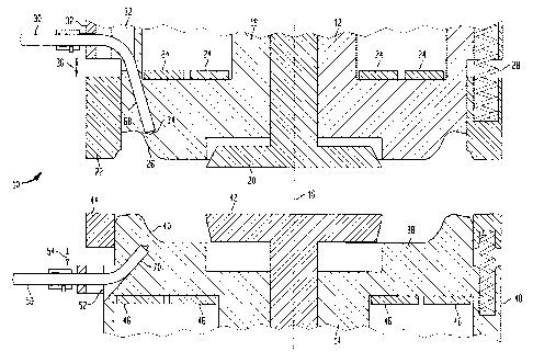
There is shown in Figures 1 and 2 a metal pressware die set 10 which
includes an upper die half (sometimes referred to in the art as the pvnch)12
and a
lower die half (sometimes referred to in the art as the die) 14. Both halves
12, 14 are
segmented presswarc dies as will be appreciated from thc discussion which
follows.
Die half 12 and die half 14 arc mounted about an axis of reciprocation 16 in
facing
relationship as shown. Die half 12 comprises generalty an upper base plate 18
provided with a knock-out 20. There is additionally provided an annulttr
pressure
ring 22 as well as heating coils 24. Base plate 18 is provided with forming
surfaces
such as surface 26 which is used to form the sidewall of a paperboard
pressware
product. It is at such surfaces that temperature control is particularly
iniporta.nt as
CA 02317872 2007-07-09
will be appreciated by one of skill in the art. There may also be provided a
plurality
of springs, such as spring 28, that can be used to bias the various parts.
Typically, between
4 and 8 springs are used to individually bias the various parts. Likewise,
knock-out
may be spring biased if so desired. It can be appreciated by one skilled in
the art
5 that the various parts of the segmented die such as prc$sure ring 22 and
lmock-out 20
are capable of movement independently of the other parts of the segmented die
such
as plate 18. Presswe ring 22 makes it particularly difficult to measure
directly the
temperature at surface 26 of base plate 18 unless one utilized an internal
temperature
probe system such as that known in the prior art as described hereinabove. In
10 accordance with the invention, there is providcd an angled flexible temF-
erature probe
that extends from the sidewall in a transverse direction as shown, that is,
transverse being substantially perpendicular to the axis of reciprocation
about which
the die is mounted and is angled towards forming surface 26 so that the tip 34
of the
temperature probe upon which the temperature sensor is located, is in
proximity to
15 surface 26. As will be appreciated hereinafter, pressure ring 22
reciprocates about a
stroke length indicatcd at 36, such that it is not possible to have a s-
ttaigbt probe
mounted on the die half 12 approach surfaec 26 in close proximity.
On the lower half of Figure 1 there is shown the lower half (die) of a
20 pressware die set which comprises a base plate 38 having, a forming surhce
40 as
well as a knock-out 42 and a draw ring shown at 44. It is additionally
provided with
heating coils 46 and a plurality of springs, such as spring 48 which may be
used to
bias the particular desired segment of the die half if so desired. Typically,
between 4
and 8 springs are used to individually bias the various parts. In accordance
with the
25 present invention there is provided an angled, flexible probe 50 extending
from the
sidewall 52 of the die half toward forming surface 40 of base plate 38. Here
again
,duc to the fact that draw ring 44 moves over a stroke length 54, it is not
possible for a
straight temperature probe to come into close proximity of forming surface 40
without interfe,rin.g with the operation of the segmented die. Thus, in
accordance with
CA 02317872 2000-11-24
16
the present invention there is provided an angled flexible temperature probe
which
can be in close proximity, i.e., 1/32 to 'ii of an inch of the forming surface
without the
need to go through the top or bottom surface of the die half which typically
needs to
be mounted on a press so that it is not readily accessible during use as noted
above.
Figure 2 is a diagram showing the die set of Figure 1 as it would appear
during the forming step, that is, upon application of pressure to a paperboard
blank,
for example, where it can be seen that the outer annular rings such as
pressure ring
22, and draw ring 44 (outer rings which are annular in nature) move from their
rest
position along the stroke lengths at 54 and 36. It can be seen that the
temperature
probes 30 and 50 are transversely mourited on the sidewall of the die outside
of the
stroke length of both the rings 22 and 44 respectively. It should also be
appreciated
that it is best to use a probe with a sensor tip such as tip 34 and a tip 56
such that the
actual temperature sensor is close to the area desired to be monitored for
temperature.
1.5 Likewise, it is desirable to see that the tip having the sensor is urged
into contact with
the surface of the base plate as close as possible to a critical forming
surface such as
surfaces 26, 40 during use. The particularly preferred system for use in
connection
with the present invention is a spring loaded bayonet type of mounting system
wherein spring loaded caps such as caps 58 and 60 are used to position the
flexible
2o temperature probes as is better appreciated as shown in Figures 3a and 3b..
There is
shown in Figure 3a a slotted cap 58 as lockingly engageable about a bayonet
fitting
64 which is affixed to a sidewall such as sidewall 32 of' die half 12. The cap
is
preferably affixed to a spring 66 as well as the temperature probe 30 and wire
31 such
that the tip of the probe can be urged against the surface of a channel such
as channels
25 68, 70 in Figures 1 and 2 in order to accurately measure temperature at the
desired
location.
It is particularly preferred to utilize a removable plate defming a cavity to
install the inventive probe on a segmented die as will be described in
connection with
CA 02317872 2000-11-24
17
Figure 4. Figure 4 shows the sidewall such as sidewall 32 of a segmented die
of the
upper half of a segmented die set sometimes referred to as the punch half.
There is
provided in a particularly preferred embodiment of the present invention a C-
shaped
retaining member 72 provided with bolt holes 74, 76 for bolting member 72 to
sidewall 32 as well as a central cavity 78 through which the probe 30 along
with a
portion of spring 66 may pass. This way channel 68 is readily available to an
operator or technician wishing to threacl probe 30 down into the base plate of
die half
12. It should be noted that a matching cavity 80 in the sidewall of the die
half is
provided so that the channel 60 niay be readily fabricated by conventional
techniques.
Turning fmally to Figure 5 it will be appreciated in accordance with the
invention that the temperature is monitored and the temperature forming
surfaces is
controlled by conventional techniques. For example, the input from a probe
such as
from probe 30, is provided to a controller such as controller 82 which
compares the
signal with a predetermined value and will provide electrical power as
appropriate to
heating coils such as heating coils 24 in order to maintain the desired
temperature at
the forming surface.