Note: Descriptions are shown in the official language in which they were submitted.
' . 3- . - < >.:::~~:v'r';:::;:::>::::..::.:::.: . .. . , :.~;:::~':>::::
:'Y
r
. tt FF\C \ o'
HF 2
3 ) . +390u 163~J- Q?52~ + .
'~::.'~::: .:_:....::.~:., . ' :>:::::::.:::. ~ ::::::.:::.., _39:::::.
.:.:,'.~>:::::::::-:::::::
4 9 85
:.: ~~ ~..T .~~. ..:1 a :. .' . :. '. ......'.'. .
~a~.::~~.......~.; x.45 - ~ ~j....~....4~~........ :~ ::......
:'::::::::::::::
:::::::::::.::::: .:::::.:. Da Prom.ionato ~ Co
:::::.::...:::.::..::::::.~:::..::::::....::.:. _ a :::~~.~.:.::::::::::::.
,.. .. i051&98D25Z T 484 , .aZ/03 ....
1
A D=sa$ws~ w=as x~c~aROr~rriG .Ar~rraH
DESCRI~T_ I01~7
The present invent_on relates to a manual, electric, air-
aperated or oil-operated c.ispenser with reciprocating action
far dispensing predetermined quantities of fl~~.id or
paste-1_ke products s~~ch as food products, toothpaste,
lubricating oils, soaps and the like.
i~ev_ces Eor dispensing pradeter::~,inea yaantity of paste-like
prcduct are known, for example, .ram U5-1~-4BG5810, wrich
discloses a dispensing device comprising a reservoir, and a
Sliding mounted p_unge= shaft, with a piston member connected
thprecf. The extent of the travel of the pistorx r.~,ember, and
therefore the vpl ume of the product dispensed, is deters~ined
by how deep the plunger shaft penetra~es into the container.
Said depth of penetration is determined by the distance that
a~: a; tuatc~r means may be monad do~~nk~ardly before it
enccunzers an adjustable a:outrtent shoulder.
'."he objact. of the invention is to provide a device of ire
type indicated above wrich is easy G~d inexpe:z$ive to
r~an~;facture and =,ahich can re used quickly ar~d easily. A
further object of the invention is .o provide a low-ecst
device ~ahict~_ can be refilled sasiiy even by unskilled
persozne-, preferably by means o. "disposable" refill
reserzoi~s or containers.
H further object of t~:e in~renLion is to provide a aev~.ce
w_zich is a~rai~.able for uw i.m~~diateiy ~~aithcut the need for
cornplax operatio=~5 to deca7t fluid cr paste form one
con~air:e: to another.
To achrsve the objects indicated abo-re, tha subject cf' t:~e
invention i s a man~,~a-~, e3 ectric, air-operated or ci_-operat;.e~
AMENOE~ SHEET
P rinte~# 10 f~33~~~~3i2 0 0 0 - o ~ - 2 0 ~ ,
~:n
I
. . ~ .: 3- 3- C> : .::.;..;..:;.. .::.>'.: :' ! c , ::.:.::::::~::~ :......
:.....::..:
. lt.E CI- , 0
Ice. 2
+3~ ~51F.3JU252- +49 89 ~3~::..: . ...: ..;...::...::.:.:: :.:;>:
'...T ::v. ~'.: ~: Y: .:.~ ,
~~..~..~. .~. :: , 3 .45 :~: '.:: ~ ..:' .::.::.:~:: < .:
~:.::~. Da-Prow t s i anato i Co ...~s....~........~.... ~ .. :(~.v.
:::::::::::....:
:::....:.: :..:.:::...:...::::.:::
:::..:::.::.::::::.:.:::::::::::.:::.:::.::.10516aiiU 5 -
::::::.~~.:::.:::::.::::.;>
::::.: :: ::::.....::. Z Z T 494 P.03/0~ ,.::.:::.:. .::.
-
1a
dispenser with reciprocating action, comprising a =esarvcir
body co_~cur>,nicating with a diet opening orltside r_he reservo'_=,
a piston= member being mounted :or slidir_g in a lea.ktig: -~
mar.~ner ins~.de t%~e reservoir bod~r, actuator means aei.~.g
provided for causing the piston member tc adca:~ce for a
travel of predeter~r:ined maximur! ex.-ent, an;~ the position of
the piston mer.~,152r remai ni~g fixed during tie return travel of
the actuator means to the starti:~q posit~.o~?, the actuator
means further comprising an operative member in order to sat
the quantity of product to be dispensed, characterized in
that the operative mem~aer is rotatable abo~;t an axis parallel
to the direction of acvance of the piston. mem'aer during the
forward travel.
Further characteristics and advantages k~iil become >rlear from.
tre fol7.owing detailed de5cr~iption of some embodi:rents oL t~~-a
invention, given rnrit:: reference to the appended drawings,
provided purely by way of non-limit'ng example, in ~~hich:
~~IEN~ED SHCE~T
Frlnted 10 p~ ~~pQ 2 0 0 0 - o ~ - 2 0
wo sr~pci'n~om o
2
Figure 1 i6 d Side view of a first embodiment of the .
invention. '
Figure 2 is a longitudinal section of a second embodiment of
the invention, .
Figure 3 is a longitudinal section of a third embodiment of
the invention,
Figure 4 is a 7.ongitudinal section of a further embodiment of
the invention,
Figure 5 is a longitudinal section of another embodiment of
the invention,
Figure 6 shows a variant of the dispenser of Figure S in
longitudinal section,
Figure 7 shows, in longitudinal section, another disperZser
which represents basically a variant of the dispenser of
Figure 2,
Figure 8 is a section through a portion of the dispenser of
Figure S, on an enlarged scale,
Figure 9 shos,rs a further embodiment of the present invention,
in longitudinal section,
Figure l0 shows a variant of the dispensez of Figure 9, in -
longitudinal section, and ,
Figure 11 is a transverse section taken on the Bile X~-X~ of
Figure l0.
CA 02318225 2000-07-20
WO 99/36333 . PCT/I199Ii100011!
3
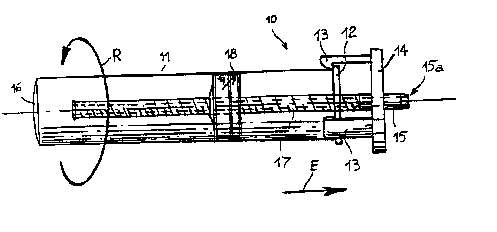
With reference now to Figure 1, a first embodiment of a
dispenser to comprises an elongate, cylindrical, cup-like
body 11 with an annular projection 12 disposed at its mouth-
The projection 12 is engaged by flexible teeth 13 projecting
from a disk-shaped structure 14 through which a tubular
dispensa.ng duct 15 extends. ' The dispensing end 15a of thG
duct 15 projects from the disk 14 on the opposite side to the
flexible teeth 13. At the opposite end to the dispensing end
15a, the duct 15 extends into the cup-l~.ke body 11 but
without touching the end 16 thereof_ The distance between
the end of the duct 15 and the end 16 of the cup-like body is
substantially equal to the distance between the mouth of the
cup 11 and the disc lg in the farthest-apart position shown
in Figure 1.
A thread 17 is formed on the outer su=face of the duct 15, at
the oppos~.te end to the dispensing end 15a, and a cyli.nd=ical
piston 18, preferably made of resilient material and mounted
for sliding in a leak-tight manner inside the cup-like body
11, ~s screwed onto Lhe thread.
When the dispensing device 1o shown in Figure 1 is in use, a
cup-like body 11 containing the fluid or the paste to be
dispensed is engaged on the flexible teeth 13 of the disk 14
so that the piston 18, which has previously been screwed to a
position close to the disc 14, closes the mouth o~ the
cup-like body 1.1_ In order to dispense a predetermined
quantity of fluid or paste, it suffices to press the bottom
16 of the cup- like body 11, moving the mouth thereof towards
the disc ~.4. The piston 18 thus moves partially into the
cup-like body 11 from which a quantity of fluid or paste
corresponding substantially to a cylindrical volume having a
base equal to Lhe inside diameter of the cup-like body 11 and
a height equal to the length of the flexzble teeth 13 emerges
CA 02318225 2000-07-20
WO 9936333 PC'f/Tf99IQ401~
4
through the axial hole in the duct l5_ Naturally, the manual
dispensing operation may be interrupted before the mouth of
the cup-like body 11 meets the disk 19 during its movement ~.a
,.
the direction of the arrow E of Figure 1. .
In order to return the dispenser to to the initial position
ready for the next dispensing operatier~, ~.t suffices to
rotate the cup-like body 11 in the direction of the arrow R
of Figure 1. Owing to the friction between the internal
walls of the cup-like body 1Z and the piston 1a, the piston
is thus rotated by the cup-like body 11 and acts on the
thread z7 of the duct 15 so as to move Lhe duct away from the
end 16 of the cup-like body and consequently to move the disk
lg away from the mouth of the cup-like body 11_
Another method may also be used to operate the dispensing
device to in ordez to dispense a guantity of fluid or paste
other chap the predetermined qua~t~.ty_ In fact, it suffices
to rotate the cup-l~.ke body 11 directly in the direction of
the arrow R of Figure 1; owing to the friction between the
internal walls of the cup-like body 11 and the piston 18, the
piston is thus rotated by the cup-like body 11 and
simultaneously gradually moves into the cup-like body, being
translated relative thereto by virtue of the thzead 17- A
quantity of fluid or paste proporzion,al to the angle of the
rotation imparted to the cup-like body 11 thus emerges from
the ax~.al hole in the duct 15; a graduated scale on which the
translational displacement of the piston 18 can be read may
be applied to the cup-like body, in order to measure this
quar~ticy. With this method, the dispenser to alwayB remains
in the initial position and is thus ready fir a subsequent
dispensing operation by one or other o~ the two
above-mentioned methods.
CA 02318225 2000-07-20
. Wp gg3 PCTIft"99IpQo10
When, as a result of successive and repeated dispensing
operations, the piston 18 has reached the end of the duct 15,
the cup-like body I1 can be released, the piston 18 can be
screwed back to a position close to the disk 14, and the
teeth 13 can be engaged on the rim 12 of the container 11
which is once more filled with the product Lo be dispensed.
Preferably, a plurality of "disposable" cup-like bodies 11,
for example, provided with tear-off closure film or the like
on their mouths, may be provided.
Figure 2 shows another embodimextt of a manual dispenser,
generally indicated 19. In this embodiment, a substantially
cylindrical container 2o has a mouth 21 covered by a cap 22
through which a dispensing rod 23 is mounted for sl~.ding
axially, the rod 23 having an aacial through duct 24 open~.ng
in the container z0 at one end and communicating, at the
othEr end, with a transverse dispensing duct 24a formed in
the body of a push-button 25 integral with the rod 23.
A resilient element, for example, a helical spring 26, is
interposed between the push-button 25 and the cap 22. A stop
device 2'7, fox example, a ring fitted in the rod 23 , defence
a travel limit for the movement of the rod 23, which is
subject to the action of Lhe spring 26. Inside the container
20, the rod 23 has an elongate portion of smaller diameter,
the outer surface of which has a thread 28 as far as the end
portion 23a of the rod 23 to which a zxavel-limit abutment 29
is fixed_
A piston body, generally ~.ndicated 30, mounted on the thread
28 of the rod 23, comprises a d~.sk 31 of t'esilienz material
preferably rubber, movable axially in the container 2o by
sliding in a leaktight mariner against the internal walls
thereof. The rubber disk 31 has an axial hole through which
CA 02318225 2000-07-20
wo ~ pcrn~ronoio
s
the rod 23 can extend and holds a plurality of jaws 32
resiliently in contact with the thread 28, the inner faces of
the jaws 32 having a thxead 33 which mates with the thread 28
of the rod 23.
When the dispenser ~.9 is in use, the piston ur~iz 30 is fir$t
of all arranged in a position close to the cap 2z. The
threaded portion of the rod 23 and at least the rubber
portion 31 of the piston body 3o are introduced into a
pre-arranged container ZO containing the product to the
dispensed, so chat the cap 2z is closed onto the mouth of the
eonzainer 20. The cap 22 may be fixed to the container 20 by
various methods, for example, by pressure, by a screw-thread,
by snap-engagement, etc. If the push-button 25 is pressed, a
predetermined quantity of product is dispensed since the
piston unit 30 is pushed into the container 20, compressirig
the product contained therein and foroing it through the duct
24 to the dispensing duct 24a. If the push-button 25 is
released, the spring 26 causes the rod 23 to return, tex~ding
to retract the piston unit 30. However, the friction exerted
by the resilient body 31 on the internal walls of the
container 20 causes the jaws 32 co open out and the thread 33
conaeguently to be released from the rod 23. Whilst the rod
23 returns to a starting position ready for a new dispensing
operation, the piston uric 30 thus remains stationary
relative to the container 2A. Repeated operat~.ons of the
push-button 25 cause the piston unit 3o to advance
progressively into the cylindrical body 20 and predetermined -
quantities of fluid product subseguently to be dispensed
until the resilient body 31 reaches the end abutment 29
disposed at the end 23a of the =od 23.
Naturally, many variat_~ns may be applied to the dispensing
device 19 illustrated in Figure 2. For example, the thread
CA 02318225 2000-07-20
W~ 99~3b333 PCT/1T99J~lpOlt!
7
28 on the body.of the rod 23 and the corresponding thread 33
on the jaws 32 may be replaced by a simple series of teeth or
grooves or the like formed on the rod 23 and corx~espond~ngly
on the internal portion of the jaws oz' clamps 32. In order
to return the p~.ston unit 3o to a position close the cap 22,
it is thus necessary to move'the jaws 32 away from the rod 23
by acting on the resilient body 3~., once the rod 23 has been
removed from the empty product container 20_
Figure 3 shows anoCher embodiment of a dispenser 34 ~n which
a dispenser unit comprising a cap 37 is mounted on the mouth
35 of a substantially cylindrical container 36. In the
embodiment shown in Figure 3, the cap 37 is mounted on the
container 36 by means of a bayonet system but, naturally, an
expert in the art wi~.l be able to identify wholly egu~.valenc,
preferably quick- fit, closure systems. An upper pertion of
the cap 37 is formed as a lever 38 articulated Co one end of
the cap 37. The lever 38 has a slot 39 end a toothed rod 40,
which extends through the slot 39 and through the cap 37 into
the container 36. is fixed to a piston 41 which can slide in
a leaktight manner inside the container 36_ An open~.ng 42
formed in the lower face of the piston 41 commur~~cates with
an ax~.al duct 43 formed inside the rod 40 and opening outside
the cap 37 at a dispensing end 44.
A drive tooth 45 mounted for sliding on the lever 38 is kept
~.n contact with the rod 4o by a resilient element 46, fvr
example, a helical spring- An operat~.ng handle 47 is fixed
to the lever 38 and a resilient member (not shown in Figure
3) keeps the lever 38 raised from the cap 37, and hence keeps
the handle 47 spaced from the surface of the container 36, in
normal condit~ons_
:then the d.~spenser 34 zs in operation, a movement of the
CA 02318225 2000-07-20
WO 99/3633.3 PCTIIT99~001110
8
handle 47 towards the body of the container 36 causes the rod
4o to be moved by the tooth 45 and the piston 91 consequently
to move towards the bottom of ;the container 36_ The axial
movement o~ the piston 46 causes the product to emerge from
the dispensing end 44 through the opening 42 and the duct 43_ --,
When the handle 47 and the never 38 have reached the end of
their travel, the resilient return element (not shewn) moves
the lever 38 away from the cap 37 and causes the drive tooth
45 to slide on the sloping surfaces of the teeth of the rod
40, which remains in the position reached. When the piston
41 has reached the bottom of the container 36 the container
can be released from the cap 37 which, together with the rod
4o and the piston 41, can be re-used w~.th a new refill of
product.
Finally, Figure 4 shoes a dispenser 48 which can be used, for
example, far dispens~r~g products, for example, soaps,
detergents, and the like, from a large-capacity container 49,
preferably fixed in a predeterm~.ned position, for example, on
a wall_ Inside the container 49, in the vicinity of its base
49a, there is an internal, preferably cylindrical. chamber SO
communicating with the interior of the container ~#9 through
an opening 51. Beneath the chamber 50, the base q9a opens
Taco a cylindrical duct 52 in which a piston 53 with a boxe
slides, the piston comprising a lower rod 54. also with an
axial hole. A pin 55 movable axially inside the hole in the
piston 53 and in the rod 54 has its lower end fixed to a push
cap 56 which is normally kept in the position indicated in _
Figure 4 by the force of a spring 57, and in the base of -
c,rhich a dispensing nozzle 58 is formed.
when the dispenser 48 is in operation, a pressure F-=rted
upwards on the push cap 56 from below causes the piston S3 to
be raised and to close the opening 51, whilst the fluid or
CA 02318225 2000-07-20
. WQ 9936333 PCT/1T99~D1~1011!
9
paste-like produce is dispensed through the nozzle 58. When
the push cap 5s ~s released, the spring 57 returns the
dispenser 48 to the position shown zn F~.gure 4, ready for a
new dispensing operation.
Another embodiment of a dispenser 6o shown in Figure 5 and,
in greater detail, in the enlarged view of Figure 8,
comprises a substantially cylindrical container 61 in Which a
piston disk 62, fvr example, but not exclusively, made of
rubber or of an eqmvalenc resilient material, is mounted for
sliding in. a leaktighc manner; a thrust plate 63 bears on the
piston d~.sk and has a central tubular guide 6~ which extends
from a central region of the thrust plate 63. The outer
surface of the tubular guide 64 has a set of teeth 65 with
sloping surfaces, preferably in the form of a single tooth
which extends around the outside of the tubular guide 64 in a
helical configuration. An operating member 66 comprises an
outer shell 67 with a mouth 68 having an annular abutment 69
for defining a travel limit against she upper edge of the
cylindrical container 61. A tubular adjustment appendage 70
extends centrally inside the outer shell 67, surrounding the
tubular guide s~ and having, at its end a thread or tooth 71
Which engages in the sloping tooth 65. The tubular appendage
7o is extended above the shell 67 to form a dispensing no221e
7z with an outer thread 73 onto which a cap 7g is screwed.
The dispensing nozzle 72 is extended downwards inside and
eoaxially with the tubular appendage 70, by a dispensing duct
~5 slidable axially in the tubular guide 64 in a leaktight
manner by virtue of a seal 76, preferably an o-ring.
Figure 6 shows a variant of the dispenser 6o which differs
basically in the different shape of the cap 74a which is
domed and has an outer cylindrical skirt 77 having a diameter
substantially equal to the diameter of the container
CA 02318225 2000-07-20
WO 99(3b333 PCT/tT99/D0010
The dispensers 6o shown in pigures 5, 6 and 8 can be
operated, after the cap 74, 74a has been unscrewed, by first
of all setting the quantity of product to be dispensed by
rotating the operating member 66 in order to ur~screw the _,
tubular appendage 70 from the tubular guide 64 by a desired
number of turns, by virtue of the movement of the tooth 71 on
the helical tooth 65. During this operation, the shell 67
moves axial~.y relative to the container 61, moving the
annular abutment 69 away from the upper edge thereof. The
metering operation just described may be assisted either by a
graduated scale applied to the parts of the dispenser which
are movable relat~.ve co one another, or by means of a sound
signal, for example, produced by means of a flexible tongue
which runs along a ramp-like track or the like during the
rotation of the shell. 67 and snaps loudly upon each rotation
or partial rvtacion of the shell 67.
Upon completion of the rotation of the shell 67, the shell
and the base of the container 61 can be rgueezed in order to
slide them axially towards one another so that the end tooth
71 pushes the tubular guide and the tht'ust plate 63 and the
piston disk 62 therewith, axially towards the base of the
container 61. The consequent reduction in volume cau~aes the
product to be dispensed through the duct 75 and to emerge
from the nozzle 72.
Another embodiment of the dispenser is shown in Figure 7.
This dispenser 80 comprises a substantially cylindr~.ca1
eontainer 81 on the upper edge 81a of which a bellows 82,
extended ac the top by a rigid cap structure 83, is engaged,
t~.xed, or formed integrally. Inside =he cap structure 83
there is a f~.rst dispensing duct 85 with an outlet noz2le 84,
preferably at the side and possibly closed _ ~ a removable cap
CA 02318225 2000-07-20
WO 99!36333 PCTlIT99lOD01t!
or plug. A tubular guide 86 extends in a central position
inside the cap structure e3 and has an extex-nal sec of teeth
87 With sloping surfaces. A rod 88 of a piston 89 slides
inside the tubular guide 86, and a second dispensing duct 90
formed inside the piston 89 communicates with the interior of
the container 81 at one end and opens into the first duct 85
at the other end. A flexible operating appendage 91 extends
from the upper wall. of the piston 89 outside the rod 88 and
terminates z.~. at least one tooth 92 which engages the set of
teeth a7 formed on the tubular guide Bs.
In the rest condition, the bellows 82 keeps the cap structure
83 raised from the container 81 and, in particular, from the
rim 81a thereof. The exertion of a pressure on the cap
structure 83 causes it to move towards the container 61, at
the same time pushing the piston 89 downwards by means of the
sec of teeth 87 which interact with the appendage 92 fixed to
the piston 89. The downward movement of the piston 89 forces
the product contained in the container 81 to pass along the
dispensing ducts 9o and 85 and to emerge from the nozzle 84.
When the cap structure 82 is released. the bellows moves the
cap structure away f;om the container 81. During this axial
movement, the end tooth 92 can slide on the set of teeth 87
by virtue of the sloping shape thereof and by virtue of the
flexibility of the appendage 91.
Figure 9 shOwS a variant of the dispensers of Figures s, s
and e, zn which a cyl~.ndrical container 100 has a p.~ston 101
on which a thrust plate 102 bears, a tubular duct 103
extending from the plate 102 in a central position, and
having a tooth 104 having a sloping surface and extending in
a helical configuration around the internal wall of the duct
1o3. A pressure member loS comprises a tubular wall l06
which is hou$ed movably at one end of the container 100, and
CA 02318225 2000-07-20
WD gg1~333 PCTOflltl
12
from the centre of which a thrust tube 107 extends, the
thrust tube having, at its end, a tooth 108 which engages the
tooth 104. A plug l09 with a dispensing nozzle 110, onto
which a cap 111 is screwed, is mounted on the other end of
the container 100.
Figures 10 and I1 ahoW a variant of the dispenser of Figure 9
~.n which the tubular duct 103 fixed to the thrust plate 1o2
moves inside the thrust tube l07 which is split
longitudinally and has fins 112 which, in the assembled
configuration of the dispenser, interfere w~.Lh the inside
wall of the container loo in prder to keep the thrust tube
10~ in contact with the tubular duct 103. It is thus possible
to remove the unit constituted by the thrust plate 102 and
the pressure member ~.os from the container loo in order to
separate the p=ensure member quickly by opening the fins 112
out radially, so as to re, use the pressure member on other
s~.milar dispensers, discarding only the components which have
come into contact with the product contained in the container
100.
The operation of the dispensers cf Figures 9 and 10 is
substantially similar to that described above with reference
to Figures 5 and 6, with the sole difference that the produce
is dispensed in the same direction as the movement of the
pressure member IOS, through the dispensing r~ozale llo
provided at the opposite end of the container loo _ In this
embodiment also, a graduated scale may be formed on the
dispenser. enabling the guanti.ty of product to be dispensed -
to be preset when the pressure member l05 is rotated before .
the actual dispensing operation_ Moreover, as already
described above, it is possible to provide a round system,
for example, by means of a flexible tongue, which provides an
acoustic indication of the number of corns or partial ~.~rns
CA 02318225 2000-07-20
WO 99/3633 PCTI~T99IOp010
13
through which the pressure member 105 is rotated prior to the
dispensing o~ the product by sliding of the pres&ure member
inside the container loo until the pressure member abuts the
edge o~ the conta~.ner .
Although all of the ernbadi.ments described above relate to
manually-operated dispensers, an expert in the art will have
no difficulty in reeogniziz~g that art alternative, electric,
air-operated or oil-operated drive system may be adopted by
known means with the use of actuator circuits operated by
such drive means.
Natura~.ly, the principle of the invention remaining the same.
the forms o~ embodiment and details of construction may be
varied widely with respect to those described and illustrated
purely by way o~ example, without thereby departing from the
scope of the present invention.
CA 02318225 2000-07-20