Note: Descriptions are shown in the official language in which they were submitted.
CA 02318447 2000-07-18
WO 99/39939 PCT/US98/24590
-1-
ENERGY ABSORBING ASSEMBLY
Technical Field
This invention relates to an energy absorbing
assembly for decelerating an object that impacts the
assembly into which an energy absorbing member is
placed.
Background Art
In many fields it is desirable to provide
assemblies which are able to decelerate, in a given,
limited distance, an object which impacts the assembly.
To do so, the assembly must absorb a significant per-
centage of the impact energy transferred by the object.
In the past, this has been accomplished physically by
providing the assembly with an energy absorbing member
for supporting deformation of the assembly in order to
absorb the energy of the impacting object.
Within a vehicle, for example, occupants
require protection from impact with interior components
such as the pillars and headrails. These structures are
typically made of steel tubing or steel channels which
are welded together ~to form the structural cage or
unitized body for the vehicle. Designers have attempted
to place energy absorbers over the pillars, headrails
and other parts of a vehicle to protect the vehicle
occupants. Prior art approaches are found in the use of
energy absorbing urethanes, rigid polymeric foams,
blocks or cells or vanes of engineered plastics, various
sheet metal configurations, metal beams, honeycombed
metal, and other geometric solids. Most of these
CA 02318447 2000-07-18
WO 99/39939 PCT/US98/24590
-2-
materials, however, while crushing generally absorb less
than the desired amount of energy for a given displace-
ment.
The desired response of an energy absorbing
material from initial loading to failure is one wherein
a near "square wave" response of force versus deflection
is produced, such that the force exerted on the deceler-
ated object is nearly unchanged over a desired range of
crush distance or deflection. Commonly owned U.S.
Patent No. 5,700,545 issued to Audi et al. discloses
such an energy absorbing structure, the disclosure of
which is herein ,incorporated by reference. The energy
absorbing member disclosed therein comprises an array of
material, such as expanded metal, configured with
vertical supporting faces which are generally orthogonal
to spacing faces lying in the plane of an incident
surface. While the energy absorption characteristics of
such a structure are improved compared with those of the
prior art, due to its configuration only the supporting
faces, representing "50% of the absorbing member, are
utilized in energy absorption. The spacing faces play
little or no part in energy absorption since they
generally lie in a plane orthogonal to the direction of
impact.
Therefore, a need exists fax an energy absorb-
ing assembly which maximizes the use of energy absorbing
members, so that maximum collapsible material is har-
nessed to produce superior energy absorbing characteris-
tics and optimize the amount of energy absorbed per unit
mass and per unit deflection of the energy absorbing
member compared with prior art structures.
CA 02318447 2000-07-18
WO 99/39939 PCT/US98/24590
-3-
It is an object of the present invention to
provide an energy absorbing assembly which decelerates
an impacting object in a given, limited distance after
engagement with the assembly.
It is a further object of the present inven-
tion to provide an energy absorbing assembly that
maximizes the energy absorption over a given distance as
compared with prior art structures.
It i:s a still further obj ect of the present
invention to provide an energy absorbing assembly which
absorbs energy in a near square-wave manner.
It is another object of the present invention
to provide an energy absorbing assembly which is adapted
for mounting on a vehicle in order to provide impact
protection.
Accordingly, an energy absorbing assembly is
provided for decelerating an object that impacts the
assembly. The assembly comprises an incident member
having an incident surface that meets the impacting.
object and at least one energy absorbing member attached
to an attachment region of an opposing face of the
incident member for accommodating deformation of the
assembly. The energy absorbing member comprises a
lattice of interconnected strands, wherein the strands
interconnect to define a plurality of cells. The energy
absorbing member is oriented such that the plane of each
cell is substantially perpendicular to the attachment
region in order to maximize energy absorption over a
given distance. The lattice collapses and at least some
CA 02318447 2000-07-18
WO 99/39939 PCT/US98/24590
-4-
of the cells become at least partially closed during
energy absorption.
The above objects and other objects, features,
and advantages of the present invention are more readily
understood from a review of the attached drawings and
the accompanying specification and claims.
Brief Description Qf The ,Drawings
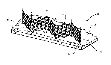
Figure 1 depicts a perspective view of the
energy absorbing assembly of the present invention;
Figure 2 is a side elevational view of a
planar embodiment of the energy absorbing member of the
present invention;
Figure 3 is a top plan view of a serpentine
embodiment of the energy absorbing member of the present
invention;
Figure 4 is a side view of a planar embodiment
of the energy absorbing member as it is deformed in a
plane perpendicular to the incident surface;
Figure 5 is a tap view of a serpentine
embodiment of the energy absorbing member as it is
deformed in a plane parallel to the incident surface;
Figure 6 is an enlarged, fragmentary view of
a single cell within the energy absorbing member of the
present invention;
CA 02318447 2000-07-18
WO 99/39939 PCTNS98/24590
_5_
Figure 7 is a force-deflection graph for the
energy absorbing member of the present invention in
which the cells are aligned such that the minor axis is
generally parallel to the direction of impact; and
Figure 8 is a force-deflection graph for the
energy absorbing member of the present invention in
which the cells are aligned such that the major axis is
generally parallel to the direction of impact; and
Figure 9 shows an energy absorbing member
attached to a typical vehicle A pillar cover;
Figure 10 shows an energy absorbing member
attached to a typical vehicle B pillar cover; and
Figure 11 shows an energy absorbing member
encased within a filler material.
Best Modes For Carr~~g Out The Invention
Referring first to Figure 1, there is depicted
an energy absorbing assembly 10 for decelerating an
object (not shown) that impacts the assembly. In the
preferred embodiment, assembly 10 comprises an incident
member 12 having an incident surface 14 that meets the
impacting object. At least one energy absorbing member
16 is attached to an attachment region 17 of an opposing
face 18 of incident member 12 for accommodating deforma-
tion of assembly 10.
Referring now to Figure 2, each energy absorb-
ing member 16 comprises a lattice of interconnected
strands 20 of a material, such as expanded metal, which
provides assembly 10 with the characteristic energy
CA 02318447 2000-07-18
WO 99/39939 PCT/US98/24590
-6-
absorption. The expanded metal from which energy
absorbing member 16 is preferably formed is available
from sources such as the McNichols Company of Tampa,
Florida. The material is available in numerous styles
and can be constructed of various materials, depending
upon the desired energy absorption characteristics of
assembly 10. Representative materials include carbon
steel, ASTM-F-1267-9-1, HD galvanized steel, aluminum
(5005 H 34), stainless steel type 304, stainless steel
type 316, and the like. If desired, a protective
coating can be applied to the expanded metal to provide
corrosion resistance.
Alternatively; the lattice could be composed
of any form of steel, plastic, or composite material.
It will be apparent to those skilled in the art that the
lattice could be formed by perforating, expanding,
burning, punching, laser cutting, or blanking a sheet.
The lattice could be formed by molding, casting, or
other solidification processes, or by welding, brazing,
or other joining processes. Following lattice forma-
tion, energy absorbing member 16 is preferably flattened
by stamping, roll-forming, or other similar processes.
Accordingly, the term "lattice" is meant to encompass
these and their equivalent structures.
Strands 20 within energy absorbing member 16
intersect to define a plurality of cells 22 (Figure 2).
Cells 22 are preferably diamond-shaped before impact of
the object, but cells 22 may be pie-shaped or polygonal
having any number of sides, with the sides being curved
or straight. The lattice structure is preferably
configured to be 1-5 cells in height. In the preferred
embodiment, energy absorbing member 16 is oriented such
that the plane of each cell 22 is substantially perpen-
CA 02318447 2000-07-18
WO 99/39939 PCT/US98/24590
_7_
dicular to attachment region 17 (best shown in Figure
1), as illustrated by lines A-A', B-B', and C-C'. Using
such a configuration, each cell may be effective in
absorbing impact energy. The terminology "substantially
perpendicular" is used to indicate the possible neces-
sity of canting the energy absorption member 16, up to
about 45 degrees, to compensate for curvature of inci-
dent member 12.
Still referring to Figure 2, the lattice
structure of energy absorbing member 16 comprises a
plurality of interconnected sectors 24, wherein each
sector 24 has a center point 26. Sectors 24 may be
coplanar, as depicted in Figure 2, or may lie in differ-
ent planes to form sawtooth, squared, serpentine, or any
other type of configuration of energy absorbing member
16. Each sector 24 further includes a plurality of
interconnected segments 28, which may be planar or
curvilinear in form, as shown in Figure 3. Planar and
curvilinear segments are joined to form a preferred,
generally serpentine configuration of energy absorption
member 16. Points A, B, and C denoted in Figure 3
correspond with points A, B, and C shown in Figure 1.
For a given curvilinear segment 28, the angle 30 within
the segment may vary between almost 0 and 180 degrees.
Preferably, the radius defined by angle 30 is 2 to 4
times the thickness of the energy absorbing material.
As depicted in Figure 4, any embodiment of
energy absorbing member 16 may be deformed within a
plane which is substantially perpendicular to incident
surface 14, in order to conform to the curvature of
incident member 12, which in some cases, may not be
perfectly flat. Similarly, any configuration of energy
absorbing member 16 may also be deformed within a plane
CA 02318447 2000-07-18
WO 99/39939 PCTNS98/24590
-8-
which is substantially parallel to incident surface 14,
as illustrated by the top view of Figure 5.
Referring now to Figure 6, a representative
cell 22 within energy absorbing member 16 is shown.
Each cell 22 is defined by a major axis 32 and a minor
axis 34, wherein major axis 32 is longer than minor axis
34. In the preferred embodiment, each cell 22 is
oriented such that its minor axis 34 is substantially
perpendicular to incident surface 14 and its major axis
32 is substantially parallel to incident surface 14, for
reasons to be explained below.
The cells 22 within the lattice cooperate to
provide a concatenated, progressive reaction to the
impact forces generated by a collision of an object with
energy absorbing assembly 10. As compression proceeds,
the cells 22 become flattened in an analogous manner to
that of the bellows of an accordion upon being squeezed.
Ultimately, however, the lattice is no longer able to
absorb the impact force. At that point, cells 22 become
collapsed, and energy absorbing member 16 yields moreso
as a collapsing column. Nevertheless, during energy
absorption the reaction to the impact forces has re-
mained substantially constant during compression of the
lattice, as will be shown below.
The actual deformation mechanics on a micro-
structural or finite element level are more detailed
and/or complex. It should be recognized that the
disclosed invention encompasses all possible strand
conformations and deformation mechanics.
The quality of the energy absorbing character-
istics of an absorber may be defined by a shape factor
CA 02318447 2000-07-18
WO 99/39939 PCT/US98/24590
-9-
which is calculated by integrating an actual force-
deflection curve for the absorber over a given crush
distance to determine the actual energy absorbed, and
then dividing this quantity by the maximum force over
the deffined distance multiplied by the deffined distance.
This calculation has the effect of dividing the actual
area under the curve by a perfect square-wave. Conse-
quently, a shape factor approaching 1.0 indicates an
absorber with better energy absorbing characteristics
than a shape factor approaching 0.
Figures 7 and 8 show force-deflection curves
for samples of energy absorbing member 16, wherein
member 16 is composed of 3/16°-22 gage flattened ex-
panded metal, member. l6 is arranged in a serpentine
configuration, and cells 22 are diamond-shaped. In
Figure 7, energy absorbing member 16 was oriented such
that minor axis 34 was generally parallel to the direc-
tion of impact. As shown, the force absorbed by energy
absorbing member 16 per unit of displacement rises upon
impact, then remains substantially constant. over a
displacement during compression of over 50% of the
original height of the energy absorbing lattice. Thus,
the force-deflection curves assume a near square wave
characteristic, as indicated by their average shape
factor of 0.8 or higher. It is desirable that the
force-deflection curve have somewhat rounded corners, so
that the object is not instantaneously accelerated or
decelerated by the impacting force.
In Figure 8, energy absorbing member 16 was
oriented such that major axis 32 was generally parallel
to the direction of impact. It can be seen these curves
do not exhibit a near square wave characteristic, which
is indicated by their average shape factor of 0.4 or
CA 02318447 2000-07-18
WO 99/39939 PCT/US98/24590
-10-
lower. Furthermore, the force "spike" present in each
curve can adversely decelerate the object, and increase
the potential for damage or bodily injury. Therefore,
the orientation of cells 22 wherein minor axis 34 is
substantially parallel with the direction of impact
constitutes the preferred embodiment of the present
invention.
Force-displacement characteristics have been
measured for a variety of lattice structures of energy
absorbing member 16. It has been found that section
length, bend angle, section height, strand width,
strand thickness, and degree of flattening as well as a
number of processing variables all impact the shape
factor. '
Another way of characterizing the performance
of an energy absorbing member is to measure the acceler-
ation vs. time curve for an object impacting the member.
For many materials, including most metals, the dynamic
acceleration vs. time curve for an object traveling at
a speed of over "2 mph is similar to the static force-
deflection curve measured at slow rates of crushing, on
the order of 0.01 mph.
A plot of acceleration vs. time is typically
used to measure the performance of a human .headform
impacting the interior of a motor vehicle. By conven-
tion, this measurement is def fined as the "Head Inj ury
Criterion" and denoted most recently by HICd. HICd is
calculated according to Federal Motor Vehicle Safety
Standard 201, which is incorporated herein by reference.
The headform by convention is usually taken as 10 lbs.
in weight and approximates the shape of the human head,
and travels.at a speed of 15 mph.
CA 02318447 2000-07-18
WO 99/39939 PCT/US98/24590
-11-
If the performance of a headform is measured
upon impact with the unitized body or cage of a motor
vehicle lacking any trim cover or energy absorbing
members, HICd is typically measured to be greater than
2000, and sometimes above 3000. HICd can be lower if the
cage is relatively flexible, the headform hits at a
glancing angle, or an aesthetic trim cover is installed.
Designers prefer HICd to be less than 1000, and sometimes
less than 800.
According to the above-described parameters
for HICd determination, a number of dynamic tests of the
energy absorbing member of the present invention were
conducted. Measurements of HICd were collected using a
drop tower test stand and a trim cover attached to a
vehicle A pillar, which normally extends upwardly
between the windshield and front door window from the
lower body to the roof on both sides of a vehicle. In
a first test, energy absorbing plastic vanes were molded
into the trim cover, resulting in an HICd of 1428. In a
second test, the energy absorbing member in a serpentine
embodiment of the present invention was attached to the
trim cover. The energy absorbingr, member contained
diamond-shaped cells and was arranged such that the
minor axis of the cells was parallel to the direction of
impact. For the four samples tested, the HICd averaged
a greatly reduced value of 723.
In the preferred embodiment, energy absorbing
assembly 10 also includes means for attaching the
incident member to a support surface, such as a pillar
or headrail of a vehicle. Attachment means include
glue, insert molding, press fits, snap fits, heat
staking, fasteners, welding, brazing, or other metal
joining methods.
CA 02318447 2000-07-18
WO 99/39939 PCT/US98/24590
-12-
Figures 9 and 10 show examples of energy
absorbing member 16 attached to the attachment region 17
of a vehicle A pillar cover 44 and a vehicle B pillar
cover 46, respectively. The vehicle B pillar extends
upwardly to the roof at a location just behind the front
door on both sides of a vehicle. While energy absorbing
member 16 is shown placed in a generally vertical
direction on A pillar cover 44 (Figure 8) and B pillar
cover 46 (Figure 9), energy absorbing member 16 may be
placed in other orientations.
Figure 11 depicts energy absorbing members 16
disposed at least partially within a filler material 48,
such as a polymeric material, a foam, a gas, or mixtures
thereof. Such a configuration might be utilized to
protect a vehicle headrail, which is attached to the
tops of the vehicle A and B pillars to form the perime-
ter of the roof of the vehicle. Impregnation of such
substances within energy absorbing assembly 10 may
improve wall buckling resistance. Various materials may
also be placed interstitially within energy absorbing
assembly 10 to provide rebound, including metal springs
and polymers exhibiting elasticity.
Other support surfaces associated with a
vehicle include an instrument panel,. a seat, a seat
back, an integrated seat restraint mechanism, a door
panel, door mounted hardware, a dome light, an overhead
console, pillar-mounted safety restraint hardware, a
headliner, a bumper, a knee bolster, a seat antisubma-
rine ramp; and a steering column. All are intended to
lie within the scope of the term ~~support surface' as
used herein.
CA 02318447 2000-07-18
WO 99/39939 PCT/US98/24590
-13-
It should be understood that the applications
of energy absorbing assembly 10 are not limited to
vehicles. In the aviation field, energy absorbing
assembly l0 may be used for arresting gear and landing
.gear, plus interior energy absorbers to protect occu-
pants. In the sports arena and other personal protec-
tion equipment markets, the disclosed assembly 10 may
usefully be embodied in' head gear (helmets for football,
skiing, hockey, etc.), teeth guards, and knee, hip,
elbow and shoulder pads. The disclosed invention also
finds utility in shipping carton protectors which would
replace or supplement existing foams. Further, energy
absorbing assembly 10 could be used as a mounting for
earthquake-resistant buildings and structures.
It is understood, of course, that while the
form of the invention herein shown and described consti-
tutes a preferred embodiment of the invention, it is not
intended to illustrate all possible forms thereof. It
will also be understood that the words used are words of
20~ description rather than limitation, and that various
. changes may be made without departing from the spirit
and scope of the invention disclosed.