Language selection

Search

Patent 2318834 Summary

Third-party information liability

Some of the information on this Web page has been provided by external sources. The Government of Canada is not responsible for the accuracy, reliability or currency of the information supplied by external sources. Users wishing to rely upon this information should consult directly with the source of the information. Content provided by external sources is not subject to official languages, privacy and accessibility requirements.

Claims and Abstract availability

Any discrepancies in the text and image of the Claims and Abstract are due to differing posting times. Text of the Claims and Abstract are posted:

  • At the time the application is open to public inspection;
  • At the time of issue of the patent (grant).
(12) Patent Application: (11) CA 2318834
(54) English Title: COPA METHOD FOR FIBEROPTIC ENDOTRACHEAL INTUBATION
(54) French Title: PROCEDE UTILISANT UNE CANULE OROPHARYNGIENNE A BALLONNET ET DESTINE A L'INTUBATION TRACHEALE DE FIBRES OPTIQUES
Status: Deemed Abandoned and Beyond the Period of Reinstatement - Pending Response to Notice of Disregarded Communication
Bibliographic Data
(51) International Patent Classification (IPC):
  • A61B 01/267 (2006.01)
  • A61M 16/04 (2006.01)
(72) Inventors :
  • GREENBERG, ROBERT S. (United States of America)
(73) Owners :
  • JOHNS HOPKINS UNIVERSITY
(71) Applicants :
  • JOHNS HOPKINS UNIVERSITY (United States of America)
(74) Agent:
(74) Associate agent:
(45) Issued:
(86) PCT Filing Date: 1999-01-26
(87) Open to Public Inspection: 1999-08-05
Availability of licence: N/A
Dedicated to the Public: N/A
(25) Language of filing: English

Patent Cooperation Treaty (PCT): Yes
(86) PCT Filing Number: PCT/US1999/000394
(87) International Publication Number: US1999000394
(85) National Entry: 2000-07-28

(30) Application Priority Data:
Application No. Country/Territory Date
09/015,219 (United States of America) 1998-01-29

Abstracts

English Abstract


The disclosed method uses a cuffed oro-pharyngeal airway (COPA) (10) as an
adjunct for fiberoptic endotracheal intubation. This allows control, and
support of the airway during the procedure. The disclosed techniques take
advantage of the upper airway distending effects of the COPA cuff (14) and
ability for continuous ventilation. In fact, using the COPA cuff (14)
appropriately with the fiberoptic scope (50) outside it, it is possible to
have the cuff augment the size of the hypopharynx, lift the epiglottis, and
facilitate fiberoptic intubation. The ability to perform fiberoptic
endotracheal intubation while effectively supporting the airway using the COPA
(10) may be advantageous in managing the difficult airway and in teaching the
technique of fiberoptic endotracheal intubation.


French Abstract

Selon le procédé de l'invention, on utilise une canule oropharyngienne à ballonnet (canule COPA) comme un instrument d'appoint lors de l'intubation trachéale de fibres optiques, ce qui permet de commander et de soutenir la canule pendant l'opération. Les techniques proposées mettent à profit l'effet de dilatation de la canule supérieure, dû au ballonnet (14) de COPA, ainsi que la possibilité d'effectuer la ventilation en continu. En utilisant le ballonnet (14) de COPA de façon appropriée, conjointement avec un dispositif de visualisation à fibres optiques (50) se trouvant à l'extérieur, on peut augmenter au moyen dudit ballonnet la taille du laryngopharynx, soulever l'épiglotte et faciliter l'intubation des fibres optiques. La possibilité d'effectuer l'intubation trachéale de fibres optiques tout en soutenant efficacement la canule au moyen de COPA (10) peut s'avérer utile lors de la manipulation d'une canule difficile ou de l'apprentissage de la technique d'intubation trachéale de fibres optiques.

Claims

Note: Claims are shown in the official language in which they were submitted.


9
I CLAIM:
1. A method for fiberoptic endotracheal intubation comprising:
providing a device comprising a cannula having a first, distal end for
placement within the pharynx of a patient, a second, proximal end adapted to
be
disposed outside of the patient's oral cavity, and a flow passage
therebetween, that
cannula having a length such that when the distal end is placed within the
pharynx,
it terminates distally at a point near the patient's epiglottis; and an
inflatable cuff
structure for forming a seal between a wall of said cannula and a wall of the
patient's pharynx, said cuff being disposed adjacent said distal end and
defining,
on inflation, a ventral/anterior portion and a posterior portion;
inserting said device, with cuff deflated, into a patient's mouth so that said
distal end of said device is disposed at a point near the patient's epiglottis
thereby
to establish an airway. column down the core of the device;
inflating said cuff structure, whereby the patient's airway is supported and
at least one of spontaneous breathing and controlled ventilation through the
flow
passage of the device can thereafter be provided;
providing a fiberoptic scope;
preloading an endotracheal tube on the fiberoptic scope so that the
fiberoptic scope is threaded through the endotracheal tube with a distal tip
of the
scope projecting beyond the endotracheal tube for insertion into the patient;
inserting said fiberoptic scope through the patient's oral cavity so that the
tip is in the throat past the uvula, whereby after insertion of said device
and
inserting of said fiberoptic scope, said fiberoptic scope is disposed
exteriorly of
said device;
advancing the tip of the fiberoptic scope so that the fiberoptic scope tip
enters the trachea;
advancing the endotracheal tube through the oral cavity and into the
trachea using the fiberoptic scope as a guide; and
removing the fiberoptic scope from the trachea

10
2. The method of claim 1, wherein said step of inserting a fiberoptic
scope precedes said step of inserting said device.
3. The method of claim 1, further comprising the step of at least
partially deflating the cuff of the device and displacing the device
proximally,
before said step of advancing the endotracheal tube, and wherein said step of
displacing said device proximally comprises pulling the device almost
completely
out of the oral cavity so that the distal tip of the device is adjacent the
teeth
whereby said device defines a bite block to protect said fiberoptic scope.
4. The method of claim 1, wherein said step of inflating said cuff
structure comprises inflating said cuff structure to seal the oro-pharynx,
distend
the upper pharyngeal structures to open further the pharyngeal airway column,
and
wherein said ventral/anterior portion is disposed on said cannula so as to
displace,
on inflation, a base of the patient's tongue, thereby locking said cannula in
place in
the pharynx.
5. The method of claim 1, wherein said step of providing a device
comprises providing a device including a tooth/lip guard having means for
attaching a stabilizing strap thereto and further comprising attaching a strap
to the
tooth/lip guard.
6. The method of claim 1, wherein said step of providing comprises
providing a device with an inflatable cuff having a ventral/anterior portion
comprising a protuberance having a length less than a length of said posterior
portion.
7. The method of claim 1, wherein said step of providing comprises
providing a device preformed to define a generally straight proximal portion
and
an upwardly arched intermediate portion.

11
8. The method of claim 1, further comprising forming said device
from a semi-rigid material that resists kinking.
9. A method for fiberoptic endotracheal intubation comprising:
providing a device comprising a cannula having a first, distal end for
placement within the pharynx of a patient, a second, proximal end adapted to
be
disposed outside of the patient's oral cavity, and a flow passage
therebetween, that
cannula having a length such that when the distal end is placed within the
pharynx,
it terminates distally at a point near the patient's epiglottis; and an
inflatable cuff
for forming a seal between a wall of said cannula and a wall of the patient's
pharynx, said cuff being disposed adjacent said distal end and defining, on
inflation, a ventral/anterior portion and a posterior portion;
inserting said device, with cuff deflated, into a patient's mouth so that said
distal end of said device is disposed at a point near the patient's epiglottis
thereby
to establish an airway column down the core of the device;
inflating said cuff structure, whereby the patient's airway is supported and
at least one of spontaneous breathing and controlled ventilation through the
flow
passage of the device can thereafter be provided;
providing a fiberoptic scope;
preloading an endotracheal tube on the fiberoptic scope so that the
fiberoptic scope is threaded through the endotracheal tube with a distal tip
of the
scope projecting beyond the endotracheal tube for insertion into the patient;
inserting said fiberoptic scope through the nasal cavity so that the tip is in
the throat past the uvula;
advancing the tip of the fiberoptic scope so that the fiberoptic scope tip
enters the trachea;
advancing the endotracheal tube into the trachea using the fiberoptic scope
as a guide; and
removing the fiberoptic scope from the trachea.
10. The method of claim 9, wherein said step of inflating said cuff

12
structure comprises inflating said cuff structure to seal the oro-pharynx,
distend
the upper pharyngeal structures to open further the pharyngeal airway column,
and
wherein said ventral/anterior portion is disposed on said cannula so as to
displace,
on inflation, a base of the patient's tongue, thereby locking said cannula in
place in
the pharynx.
11. The method of claim 9, wherein said step of providing a device
comprises providing a device including a tooth/lip guard having means for
attaching a stabilizing strap thereto and further comprising attaching a strap
to the
tooth/lip guard.
12. The method of claim 9, wherein said step of providing comprises
providing a device with an inflatable cuff having a ventral/anterior portion
comprising a protuberance having a length less than a length of said posterior
portion.
13. The method of claim 9, wherein said step of providing comprises
providing a device preformed to define a generally straight proximal portion
and
an upwardly arched intermediate portion.
14. The method of claim 9, further comprising forming said device
from a semi-rigid material that resists kinking.
15. The method of claim 9, further comprising at least partially
deflating the cuff of the device and displacing the device proximally, before
said
step of advancing the endotracheal tube.
16. The method of claim 9, wherein said step of inserting the fiberoptic
scope comprises inserting the fiberoptic scope through one of the patient's
nares
and through the nasal cavity.

13
17. A method for fiberoptic endotracheal intubation comprising:
providing a device comprising a cannula having a first, distal end for
placement within the pharynx of a patient, a second, proximal end adapted to
be
disposed outside of the patient's oral cavity, and a flow passage
therebetween, that
cannula having a length such that when the distal end is placed within the
pharynx,
it terminates distally at a point near the patient's epiglottis; and an
inflatable cuff
structure for forming a seal between a wall of said cannula and a wall of the
patient's pharynx, said cuff being disposed adjacent said distal end and
defining,
on inflation, a ventral/anterior portion and a posterior portion;
inserting said device, with cuff deflated, into a patient's mouth so that said
distal end of said device is disposed at a point near the patient's epiglottis
thereby
to establish an airway column down the core of the device;
inflating said cuff structure, whereby the patient's airway is supported and
at least one of spontaneous breathing and controlled ventilation through the
flow
passage of the device can thereafter be provided;
providing a fiberoptic scope having a distal tip;
providing an endotracheal tube;
passing the endotracheal tube alongside the device and into the throat past
the uvula;
positioning the fiberoptic scope one of within said flow passage and
alongside said device;
passing the endotracheal tube into the trachea; and
observing the endotracheal tube at least one of passing alongside said
device and passing into the trachea.
18. The method of claim 17, wherein said step of inflating said cuff
structure comprises inflating said cuff structure to seal the oro-pharynx,
distend
the upper pharyngeal structures to open further the pharyngeal airway column,
and
wherein said ventral/anterior portion is disposed on said cannula so as to
displace,
on inflation, a base of the patient's tongue, thereby locking said cannula in
place in
the pharynx.

14
19. The method of claim 17, wherein said step of providing a device
comprises providing a device including a tooth/lip guard having means for
attaching a stabilizing strap thereto and further comprising attaching a strap
to the
tooth/lip guard.
20. The method of claim 17, wherein said step of providing comprises
providing a device with an inflatable cuff having a ventral/anterior portion
comprising a protuberance having a length less than a length of said posterior
portion.

Description

Note: Descriptions are shown in the official language in which they were submitted.


CA 02318834 2000-07-28
WO 99/38432 PCT/US99/00394
COPA METHOD FOR FIBEROPTIC ENDOTRACHEAL INTUBATION
BACKGROUND OF THE INVENTION
Field of the Invention
The present invention relates to fiberoptic endotracheal intubation and,
more particularly, to a method for fiberoptic endotracheal intubation using a
cuffed oro-pharyngeal airway (COPA).
2. Description of the Related Art
Fiberoptic endotracheal intubation has been used for several years and may
be performed orally or nasally. Conventional methods of fiberoptic
endotracheal
intubadon use the internal passage of a device, such as a laryngeal masked
airway,
Combitube~, Ovassapian Airway, or the like. The main disadvantage of passing
the fiberoptic scope through an airway device is the increased airway
resistance
encountered, since the fiberscope occupies a significant portion of the lumen
of
the device. Moreover, it is impossible with such techniques to provide
continuous
airway support, either controlled inspired gas concentration or
assisted/controlled
positive pressure manual ventilation.
Fiberoptic intubation with the patient under general anesthesia presents
special problems. The main disadvantage of intubation under general anesthesia
is
2 0 that the tongue and pharyngeal tissues lose their tonicity and close down
the
pharyngeal space, blocking visualization of the larynx. Thus, in such
circumstances, to minimize apnea time, and to facilitate laryngeal exposure,
an
assistant is required.
SUMMARY OF THE INVENTION
The disclosed method uses the exterior of a cuffed oro-pharyngeal airway
(COPA), preferably of the type described in U.S. Patent Nos. 5,653,229 and
5,443,063, the disclosures of which are incorporated herein by this reference,
between the cuff and the pharyngeal wall to stabilize the fiberoptic scope.
Using
3 0 the COPA as an adjunct for fiberoptic endotracheal intubation allows
control and
support of the airway during the procedure, using various anesthetic
techniques, in

CA 02318834 2000-07-28
WO 99/38432 PCT/US99/00394
2
an acceptable amount of time, which would be expected to decrease with
experience. The ability to perform fiberoptic endotracheal intubation while
effectively supporting the airway using the COPA may be advantageous in
managing the difficult airway and in teaching the technique of fiberoptic
endotracheal intubation.
The disclosed techniques take advantage of the upper airway distending
effects of the COPA cuff and ability for continuous ventilation. In fact,
using the
COPA cuff appropriately with the fiberoptic scope outside it, it is possible
to have
the cuff augment the size of the hypopharynx, lift the epiglottis, and
facilitate
fiberoptic intubation.
The COPA may be used both for oral endotracheal intubation and for nasal
endotracheal intubation. Indeed, using the cuffed oro-pharyngeal airway during
intubation with a fiberoptic scope allows airway support and assists in
spontaneous breathing or controlled ventilation while positioning the
fiberoptic
scope from either the oral or nasal approach.
Conformability of the surrounding tissues and the cuff relative to the
fiberoptic scope enables passage of the scope behind or on the outside of the
COPA cuff without significant interference with its seal. Thus, positive
pressure
ventilation and special assistance in spontaneous ventilation can still be
managed
2 0 during fiberoptic laryngoscopy and endotracheal intubation.
As noted above, performance of the fiberoptic technique using the COPA
allows the administration of oxygen or other gases or vapors, and does not
require
that the patient be apenic for each fiberoptic attempt. This is one of the
major
advantages of the method.
2 5 Other objects, features and characteristics of the present invention, will
become more apparent upon consideration of the following detailed description
and the appended claims with reference to the accompanying illustrations, all
of
which form a part of this specification.

CA 02318834 2000-07-28
WO 99/38432 PCTNS99/00394
3
BRIEF DESCRIPTION OF THE DRAWINGS
FIGURE 1 is a perspective view of a cuffed oro-pharyngeal airway that
may be used as an adjunct to fiberoptic endotracheal intubation in accordance
with
the present invention;
FIGURE 2 is an elevational view of another airway configuration that may
be used in accordance with the present invention;
FIGURE 3 is an elevational view showing a cuffed oro-pharyngeal airway
(COPA) disposed within the patient's oral cavity and with the cuff inflated,
and
wherein a fiberoptic scope is fed through one of the naves and fed down behind
the
soft palate;
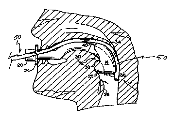
FIGURE 4 is an elevational view showing cuffed oro-pharyngeal airway
(COPA) disposed within the oral cavity and with the cuff inflated, and wherein
a
fiberoptic scope is disposed between the COPA cuff and the pharyngeal wall.
DETAILED DESCRIPTION OF THE PRESENTLY
PREFERRED EXEMPLARY EMBODLIUVIENTS
In accordance with the invention, a Guedel-type oral airway or a similarly-
configured cannula 12, 12' having an inflatable component 14 which is
selectively
inflated through tubel6 and check valve 18, is used to establish a supported
2 0 airway during fiberoptic oral or nasal intubation. The illustrated
structure is
described in detail in Patent Nos. 5,653,229 and 5,443,063.
At the proximal end of airway 12, 12', a connector 20 is provided to couple
the airway to an anesthesia or other ventilation circuit. A bite block 22
and/or
tooth/lip guard 24 are also preferably provided at the proximal end. The lip
guard
2 5 24 may have ears with apertures 42 and/or hooks for strap attachment.
In the illustrated embodiment, on inflation, the inflatable component or
cuff 14 defines a ventraUanterior projecting portion 28 which anteriorly
displaces
the base of the tongue 30 so that the tongue may rest against the seat 32
created by
portion 28. The posterior side 34 of the device supports the device in the
oral
3 0 cavity and seals with the pharyngeal tissues to minimize leakage around
the
device. Attachment at 38 and 40 restricts movement of the cuff 14.

CA 02318834 2000-07-28
WO 99/38432 PCT/US99/00394
4
Fiberoptic endotracheal intubation in accordance with the invention may
be performed through one of the nares as a nasal intubation or through the
mouth
for oral intubation. Both procedures are described in detail hereinbelow.
An exemplary intubation procedure in accordance with the invention is as
follows:
Prepare the fiberoptic scope 50 by preloading an endotracheal tube (not
shown). Specifically, the fiberoptic scope 50 is threaded through the
endotracheal
tube and the endotracheal tube is positioned highlproximal on the scope. This
leaves the distal tip of the scope free for insertion into the patient and
manipulation. Any size endotracheal tube which can be positioned on the
fiberoptic scope can be used; the size of the COPA is irrelevant thereto.
Moreover, the endotracheal tube. may be either cuffed or uncuffed. .If the
tube is
cuffed, the cuff should be deflated and smoothed back distally.
Position the patient supine with IV and monitors in place and preoxygenate
and premedicate as deemed necessary or desirable. Then induce anesthesia
using,
for example, either an intravenous or inhalational anesthetic. Alternatively,
regional airway blocks may be performed and the patient thus remains awake.
Insert the COPA 10 and inflate the cuff 14 according to the package
directions. Secure the strap to hold the COPA in place. Attach the circuit and
2 0 assist ventilate with oxygen as necessary.
It is possible to establish continuous positive airway pressure (CPAP), e.g.
about 10-20cm H20, by closing off the pop-off valve on the circuit. At this
point,
the patient is spontaneously breathing with the COPA supporting the airway.
While the patient is breathing with the COPA in place, place the tip of the
2 5 fiberoptic scope 50 through one of the nares (or through another orifice
such as the
orbit, sinus) for nasal intubation (FIG. 3) or between the COPA cuff and the
pharyngeal wall for oral intubation (FiG. 4).
Advance the tip of the fiberoptic scope beyond the distal edge 36 of the
COPA cuff to emerge in the hypopharynx at the level just above the epiglottis
26
3 0 and vocal cords. If the cords are not visible at this point:

CA 02318834 2000-07-28
WO 99/38432 PGT/IJS99/00394
1 ) make sure that the scope hasn't turned or twisted and that the scope is
contacting a tonsil;
2) make sure that the scope has not been advanced too far so as to be at
the gastroesophageal junction or passed into the esophagus;
5 3) tip up the scope to look slightly more ventrally (vallecula);
4) tip the scope down to look posterior to the epiglottis;
5) advance the scope (the scope may not have cleared the COPA cuff);
6) lift the epiglottis by performing a simple head tilt or chin lift.
At this point, ideally, the patient is spontaneously breathing with the
COPA supporting the airway and the scope enveloped by the postern-lateral
{oral)
or posterior (nasal) aspect of the inflated cuff. The seal of inspired and
expired
gas is not generally affected by the presence of the scope. The COPA cuff is
compliant enough to seal around the scope and the wall of the pharynx.
Upon visualizing the vocal cords, it is preferable to deepen the general
anesthetic or anesthetize the vocal cords and trachea locally.
Once the patient is prepared for tracheal stimulation, the trachea may be
penetrated with the fiberscope. Pass the fiberoptic scope deeply enough into
the
trachea so as to be sure that the tip will not become dislodged with patient
movement or small scope manipulations.
2 0 Hold the fiberscope in place and deflate the COPA slightly and pull the
COPA almost completely out. By leaving the tip of the COPA at the teeth, e.g.,
left premolars and molars, it functions as a protective bite block to reduce
risk of
damaging the fiberoptic scope. Pass the preloaded endotracheal tube into the
trachea using the fiberoptic scope as a stylet or guide.
2 5 Should the beveled tip of the endotracheal tube become caught on the
posterior arytenoids, it may be helpful to rotate the tube 180° around
the axis of
the scope to position the bevel into the airway and make passage into the
trachea
easier.
At this point it is prudent to re-visualize the caring and observe the
3 0 endotracheal tube (ETT) as one removes the fiberoptic scope, noting the
presence
and position of the ETT in the trachea. This allows confirmation that the ETT
is

CA 02318834 2000-07-28
WO 99138432 PCT/US99100394
6
in midposition of the trachea and provides the immediate opportunity to re-
intubate if the patient is inadvertently extubated while removing the scope.
Completely remove the scope, inflate the ETT cuff and attach the circuit to
the ETT. A positive end-tidal COz will confirm that the ETT is in the trachea.
The deflated COPA may be left in the mouth of the patient as a bite block
to protect inadvertent biting of the ETT.
EXAMPLE
The effectiveness of the device as an adjunct to fiberoptic endotracheal
intubation was evaluated.
METHOD
Thirty-eight (38) adult patients undergoing general anesthesia were
studied. Patients 42117 years old, 72~15 kg (mean t standard deviation)
received
various anesthetic techniques including midazolam, alfentanyl, propofol (bolus
and/or infusion), isoflurane (as maintenance). After achieving an adequate
depth
of anesthesia, an appropriately sized COPA (9cm, n=16; lOcm, n=15; l lcm, n=7)
was placed, strap applied, cuff inflated, and the patient allowed to
spontaneously
ventilate (confirmed by filling of the anesthesia bag, ETCOa, and oxygen
saturation). Eight patients (21 %) then received vercuronium and were hand
ventilated via the COPA. Laryngoscopy was then accomplished by passing the
fiberscope along the outside of the COPA, between the inflated cuff and right
posterior-lateral wall of the pharynx. Vocal cords were identified and, after
the
fiberscope was passed to the canna, the COPA was removed and a preloaded 7.0
mm cuffed ETT was positioned and secured in the trachea.
2 5 RESULTS
For this study, median time from initial placement of the scope in the
airway to,attachment of the anesthesia circuit to the ETT was 138 secs for all
intubations, and 98 secs for nasal intubation, and decreased with experience.
The procedure was aborted in one patient due to copious secretions.
3 0 Another patient experienced transient hypoxemia (low Sa02=64%) secondary
to

CA 02318834 2000-07-28
WO 99/38432 PCTNS99/00394
7
coughing on passing the cords, without sequelae. No other potentially serious
complications were associated with the procedure.
CONCLUSIONS. The COPA may be a useful adjunct to fiberoptic
endotracheal intubation, allowing control and support of the airway during the
procedure, using various anesthetic techniques, in an acceptable amount of
time.
The ability to perform fiberoptic endotracheal intubation while effectively
supporting the airway using the COPA may be advantageous in managing the
difficulat airway or teaching fiberoptic technique.
While the oral intubation procedure has been described with reference to
the currently preferred process of inflation of COPA cuff before the
flberoptic
scope is advanced into the patient's oral cavity, in the alternative, before
insertion
of the COPA, the fiberoptic scope is appropriately lubricated using lidocaine
jelly
or surgilube, or the like and is gently laid in the throat of the patient so
that the tip
is just past the uvula. In that event the scope will be up against the upper
teeth,
perhaps up against the right biscupid/canine and coursing into the mouth along
the
hard palate just to the right of the midline with the tip ending up next to
but
perhaps a centimeter beyond (deeper in the throat) than the uvula. Then the
deflated cuff can be placed in the mouth so that the scope will be between the
COPA and the right upper oropharynx. The COPA cuff is then inflated assuring
2 0 that the base of the tongue is high up in the cup of the cuff so that the
bulk of the
base of the tongue rests above (proximal to) the ventral (smaller) portion of
the
cuff. The cuff is then inflated enough to seal the airway as would normally be
done. Then the strap is secured and the circuit attached for ventilation.
Again,
e.g., about a 10-20cm Hzo CPAP is established. At this point the visualization
of
2 5 the cords and subsequent steps of the process described above are
undertaken to
complete the endotracheal intubation procedure.
As is apparent from the foregoing, ventilation of the patient can be
maintained throughout the intubation procedure and intubation can be performed
by one person even in the event the patient is under general anesthesia.
3 0 Performance of fiberoptic intubation in a child can be performed using the
same or similar techniques as with the COPA in the adult. An alternative to

CA 02318834 2000-07-28
WO 99/38432 PCTNS99/00394
8
having the fiberoptic scope pass through the ETT would be to observe the
endotracheal tube passing alongside or into the trachea by positioning the
fiberoptic scope either within the COPA or alongside it. A distinct advantage
of
fiberoptic intubation using the COPA over the laryngeal masked airway (LMA) is
that one does not need to blindly place the LMA into an area that is
presumably
abnormal, thus decreasing the risk of causing trauma to fragile mucosa, the
hypopharynx, and laryngeal structures. An additional advantage is that one is
not
limited to a smaller sized ETT. ETT size becomes an issue, and a potential
problem, when it is to be passed through the lumen of another device.
While the invention has been described in connection with what is
presently considered to be the most practical and preferred embodiment, it is
to be
understood that the invention is not limited to the disclosed embodiments,
but, on
the contrary, is intended to cover various modifications and equivalent
arrangements and procedures included within the spirit and scope of the
appended
claims.

Representative Drawing
A single figure which represents the drawing illustrating the invention.
Administrative Status

2024-08-01:As part of the Next Generation Patents (NGP) transition, the Canadian Patents Database (CPD) now contains a more detailed Event History, which replicates the Event Log of our new back-office solution.

Please note that "Inactive:" events refers to events no longer in use in our new back-office solution.

For a clearer understanding of the status of the application/patent presented on this page, the site Disclaimer , as well as the definitions for Patent , Event History , Maintenance Fee  and Payment History  should be consulted.

Event History

Description Date
Inactive: IPC from MCD 2006-03-12
Inactive: Office letter 2005-07-27
Revocation of Agent Requirements Determined Compliant 2005-07-27
Revocation of Agent Request 2005-06-16
Inactive: Dead - RFE never made 2005-01-26
Application Not Reinstated by Deadline 2005-01-26
Deemed Abandoned - Failure to Respond to Maintenance Fee Notice 2005-01-26
Inactive: Abandon-RFE+Late fee unpaid-Correspondence sent 2004-01-26
Letter Sent 2002-06-07
Reinstatement Requirements Deemed Compliant for All Abandonment Reasons 2002-05-24
Deemed Abandoned - Failure to Respond to Maintenance Fee Notice 2002-01-28
Inactive: Cover page published 2000-10-25
Inactive: First IPC assigned 2000-10-22
Inactive: Notice - National entry - No RFE 2000-10-11
Letter Sent 2000-10-11
Application Received - PCT 2000-10-06
Application Published (Open to Public Inspection) 1999-08-05

Abandonment History

Abandonment Date Reason Reinstatement Date
2005-01-26
2002-01-28

Maintenance Fee

The last payment was received on 2004-01-09

Note : If the full payment has not been received on or before the date indicated, a further fee may be required which may be one of the following

  • the reinstatement fee;
  • the late payment fee; or
  • additional fee to reverse deemed expiry.

Patent fees are adjusted on the 1st of January every year. The amounts above are the current amounts if received by December 31 of the current year.
Please refer to the CIPO Patent Fees web page to see all current fee amounts.

Fee History

Fee Type Anniversary Year Due Date Paid Date
Basic national fee - small 2000-07-28
Registration of a document 2000-07-28
MF (application, 2nd anniv.) - small 02 2001-01-26 2001-01-03
Reinstatement 2002-05-24
MF (application, 3rd anniv.) - small 03 2002-01-28 2002-05-24
MF (application, 4th anniv.) - small 04 2003-01-27 2003-01-07
MF (application, 5th anniv.) - small 05 2004-01-26 2004-01-09
Owners on Record

Note: Records showing the ownership history in alphabetical order.

Current Owners on Record
JOHNS HOPKINS UNIVERSITY
Past Owners on Record
ROBERT S. GREENBERG
Past Owners that do not appear in the "Owners on Record" listing will appear in other documentation within the application.
Documents

To view selected files, please enter reCAPTCHA code :


To view images, click a link in the Document Description column. To download the documents, select one or more checkboxes in the first column and then click the "Download Selected in PDF format (Zip Archive)" or the "Download Selected as Single PDF" button.

List of published and non-published patent-specific documents on the CPD .

If you have any difficulty accessing content, you can call the Client Service Centre at 1-866-997-1936 or send them an e-mail at CIPO Client Service Centre.


Document
Description 
Date
(yyyy-mm-dd) 
Number of pages   Size of Image (KB) 
Representative drawing 2000-10-24 1 14
Abstract 2000-07-27 1 63
Description 2000-07-27 8 378
Claims 2000-07-27 6 232
Drawings 2000-07-27 2 62
Reminder of maintenance fee due 2000-10-09 1 110
Notice of National Entry 2000-10-10 1 193
Courtesy - Certificate of registration (related document(s)) 2000-10-10 1 120
Courtesy - Abandonment Letter (Maintenance Fee) 2002-02-24 1 182
Notice of Reinstatement 2002-06-06 1 172
Reminder - Request for Examination 2003-09-28 1 112
Courtesy - Abandonment Letter (Request for Examination) 2004-04-04 1 167
Courtesy - Abandonment Letter (Maintenance Fee) 2005-03-22 1 174
PCT 2000-07-27 6 221
Fees 2002-05-23 1 43
Correspondence 2005-06-15 6 448
Correspondence 2005-07-26 1 22
Correspondence 2005-07-21 7 370