Note: Descriptions are shown in the official language in which they were submitted.
CA 02318933 2000-07-20
WO 99/37465 PCT/NZ99/00006
"APPARATUS AND METHODS FOR TWIN SHEET THERMOFORMING"
Fietd of the Invention
This invention relates apparatus and methods for twin sheet thermoforming and
in particular to improved methods and apparatus for removing seams from formed
articles.
Description of the Prior Art
Twin sheet thermoforming is increasingly proposed for the formation of large
articles, in applications such as refrigerator cabinets, arid other appliance
cabinets have
been envisaged, for example in US Patent 5,374,118. In that patent it is
suggested that
the removal of the seam and the flange may be accomplished in the mould cavity
by an
independently actuated knife positioned in. a channel in one mould half
immediately
adjacent the mould cavity. A part thermoformed and trimmed in this manner
inevitably
has less strength at the weld as there is no pinch-offregion on the mould
halves adjacent
the mould cavity, and consequently the weld (if the flange is trimmed right up
against
the part to eliminate further processing) is weak.
In general for strong welds a significant compression ofthe material in the
pinch
off region is desirable to induce significant plastic displacement into the
region of the
weld, usually manifesting as a fillet on the inside thereof. This necessarily
requires
provision of opposed surfaces on opposed mould halves in the pinch-off region
to
achieve the necessary compression, eliminating the ability to locate cutting
apparatus
such as the knives of the above-mentioned US Patent. Consequently articles
formed in
this manner generally are removed from the mould with the flange still
attached, the
flange and seam being subsequently machined off. This clearly adds further
labour or
capital-intensive steps to the manufacturing process and can also impinge on
the
aesthetic appeal of the article.
Summary of the Invention
It is therefore an object of the invention to provide apparatus and/or methods
for
twin sheet thermoforming which goes some way towards overcoming the above
CA 02318933 2000-07-20
WO 99/37465 PCT/NZ99100006
-2-
disadvantages or which will at least provide the public with a useful choice.
In a first aspect the invention consists in a mould for twin sheet
thermoforming
wherein one of the mould halves includes a retractable pinch-off region, which
is able
to retract relative to the remainder of said mould half upon application of a
force thereto
greater than a predetermined force, such that the remainder of the mould half
may
cooperate with the second mould, on further closing, half to shear off the
seam of a
thermoformed article.
In a second aspect the invention consists in a mould for twin sheet
thermoforming including a pinch-off region substantially as herein described
in
accordance with and as illustrated by the accompanying drawings.
In a third aspect the invention consists in a method for producing a pre-
trimmed
twin sheet thermoformed article wherein a pair of mould halves are brought
together to
join respective sheets in a pinch-off region, and to cause significant
thickness reduction
in the pinch-off region, and subsequently causing the pinch-off region of one
said
mould half to retract relative to the rest of said mould half, to thereby
allow said mould
halves to close further, and closing said mould halves further to cooperate to
cut offthe
seam of the thermoformed article.
In a fourth aspect the invention consists in a method for producing a pre-
trimmed
twin sheet thermoformed article substantially as herein described with
reference to and
as illustrated by the accompanying drawings.
In a f:fth aspect the invention consists in an article formed by method and/or
apparatus according to any one of the preceding paragraphs.
To those skilled in the art to which the invention relates, many changes
in construction and widely differing embodiments and applications of the
invention will
suggest themselves without departing from the scope of the invention as
defined in the
appended claims. The disclosures and the descriptions herein are purely
illustrative and
are not intended to be in any sense limiting.
Brief Description of The Drawings
The preferred form of the present invention will now be described with
reference
to the accompanying drawings in which;
CA 02318933 2000-07-20
WO 99/37465 PCT/NZ99/00006
-3-
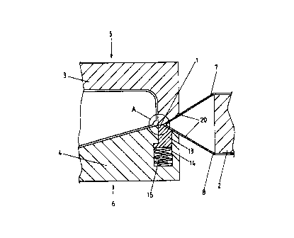
Figure 1 is a cross-sectional elevation through one side of a twin sheet
thermoforming mould according to the present invention,
Figures 2a - 2c are close up views of the pinch-off region of the mould of
Figure
1, including the region encircled by circle A, in different stages ofthe
trimming process,
in Figure 2a with the part formed but the seam not yet compressed, in Figure
2b with
the seam compressed to provide weld reinforcement, and in Figure 2c with the
upper
mould half depressing the pinch off member of the lower mould half to shear
the seam
from the part, and
Figure 3 is a cross-sectional elevation through the edge region of a mould
half
showing detail of one embodiment of the pinch off member and its retention in
the
mould half.
Detailed Description of the Preferred Embodiments
With reference to Figure 1, that area of a thermoforming mould is shown in
cross-section where the joining of the twin sheets occurs at a pinch-off
region 1. In the
thermoforming process the twin sheets, which are initially planar and parallel
and
mounted for example on supporting frame 2, are formed and joined by the action
of the
mould halves 3, 4 in the direction of arrows S, 6 and assisted by suction in
the mould
cavity or internal pressure between the sheets or both. These aspects of the
thermoforming process are well known in the art and do not form part ofthe
invention.
Referring to Figure 2a , the mould halves 3, 4 are brought together,
stretching
and forming the sheets 7, 8 until the sheets meet at the pinch-off region and
contact at
a seam 19 where they pass over the pinch off region of each mould half. The
mould
halves 3 and 4 include complementary surfaces 10 and 11 respectively in the
pinch-off
region. Referring to Figure 2b the mould halves are brought further together
to reduce
the thickness of the contacted region of sheets 7 and 8 to a thickness
substantially less
than the combined thickness of the undeformed sheets. Material is thereby
forced from
the pinch-off region to form an internal reinforcement 12.
As illustrated in the drawings, in the present invention, one mould half, 4,
incorporates a pinch-off region which is moveable relative to the remainder of
that
mould half in a direction away from the direction of travel of that mould
half. In
particular a pinch-off member 13 is disposed within a channel 14 in the mould
half and
CA 02318933 2000-07-20
WO 99/37465 PCT/NZ99/00006
-4-
is held in its usual position by a spring 15 which is preferably pre-
compressed so that
a particular level of force against the member 13 must be applied before it
will retract
into the cavity 14. Thus in Figure 2b, although the moulds have been brought
together
close enough to compress the plastic material in the pinch off region and to
extrude it
from the pinch of region to provide a weld reinforcement wt the join between
the two
sheets, the pinch-off member 13 has not yet been subjected to sufficient force
to cause
it to retract into the cavity 14. With the elastic support of the pinch-off
member as
depicted it is important that the mould halves are not brought together too
quickly,
which could result in sufficient dynamic forces to move the pinch-off member.
Alternatives to the member, spring and channel may readily suggest themselves,
such as are mentioned below, however the configuration shown is simple, and
provides
for automatic actuation by the normal movement of the mould halves in the
moulding
process.
As mentioned above, there are many alternatives to the use of a pre-compressed
spring. If a spring is used then, rather than being pre-compressed, an
appropriate effect
can be achieved using a spring of sufficiently high stiffness, or by
separately retaining
the spring against movement until reduced thickness has been achieved. As an
alternative to a spring, hydraulic or pneumatic systems may be utilised either
in a full
sealed cavity conf guration or with hydraulic or pneumatic actuators, which
may make
use of automated pressure relief valves, or valves activated in a separately
controlled
manner once the reduced thickness is reached. Similarly electrical or
mechanical
activation systems are also possible operating on a release and return basis.
Referring to Figure 2c the mould halves are then bought still closer. As the
gap
in the pinch off region narrows the force compression required to extrude
further
material from the cavity rises, particularly as the material cools in the
region of its
contact with the mould halves. Once the force being applied to the member 13
in the
pinch-off region, by closing of the mould halves, exceeds the threshold set by
the pre
compression of spring 1 S, the member 13 will retract into the cavity 14 with
continued
closing of the mould halves 3, 4. As illustrated in Figure 2c, a lip 16 being
the edge of
the cavity 14 will come to overlap into the cavity of the other mould half 3.
In this
manner the faces 17 of mould half 3 and 18 of mould half 4 will overlap with a
close
CA 02318933 2000-07-20
WO 99137465 PCT/NZ99100006
-5-
tolerance, and in doing so the respective edges will shear off the seam region
19 and
other flanges 20 of the thermoformed article. To improve the finished edge of
the
thermoformed article, where the seam has been removed by the shearing action
of the
faces 17 and 18, the mould halves should be subject to a minimum horizontal
tolerance
to give an accurate maximum separation 21 between the faces 17 and 18. Ideally
this
separation would be non-existent, however in practice bringing the mould
halves
together without clashing between the edges 30, 31 of the mould halves
requires
provision of a small tolerance. The maximum separation of the edges which will
still
provide adequate surface finish is dependent on the material being
thermoformed, its
properties and its thickness, and also on the aesthetic requirements of the
product being
formed. A separation of O.lmm has been found appropriate when thermoforming
ABS
plastics for use in domestic appliances. Alignment posts or other similar
means may be
provided to provide accurate horizontal registration between the mould halves
as the
mould halves come together, allowing the small tolerance to be achieved in a
mass
manufacture environment.
With reference to Figures 1 and 3, the pinch-off member 13 is subject to
continued force from the spring 15, and is retained in the cavity against such
spring
force by a retaining means comprising in the embodiment depicted the action of
an
abutment 22 depending horizontally from the lower edge of member 13, against a
ledge
23 provided in the channel I4. Assembly of the mould half in this manner may
be easily
provided by the inclusion of a sheath part 25 in the overall assembly.
Clearly alternatives to the abutment method of retention as described above
are
possible and many would suggest themselves to persons skilled in the art. For
example,
the pinch-off member may include two or more slotted apertures extending
laterally
there through, with dowels passing through the apertures and secured to the
mould so
that the pinch-off member may move up and down with the dowels moving within
the
slots, and with the movement of the pinch-off member being restricted by the
action of
the dowels against the slot ends. This configuration may allow for a more
compact
mould assembly method with machinery of a simple rectangular channel to retain
the
pinch-off member.
The present invention thereby provides thertnoforrning mould apparatus of
CA 02318933 2000-07-20
WO 99/37465 PCT/IYZ99/00006
-6-
simple form and actuation which allows both significant material displacement
in the
pinch-off region, and an effective and aesthetic cut-off or trimming of the
formed
article, without the use of separate knife actuation or other independently
actuated parts.
The forming and trimming of the part is accomplished in one action, leaving
the part
ready for removal, or for example foam filling while still in the mould. The
requirement
for manual part trimming or a separate automated trimming station (with its
associated
alignment and part set-up operations) is eliminated while the weld
reinforcement is
retained.
It will be appreciated that the level of material displacement achieved can be
controlled by adjustment of the force provided by spring 15, and its pre-
compression.
As an alternative, and for set tolerancing, means may be provided whereby the
member
13 is rigidly forced backwards when the required thickness is achieved, in
which case
the spring 15 may be happily left in an over-compressed state. Such means may
comprise for example a plurality of pimples or ridges 28 on the top surface of
the
member 13, which act against the face 10 of the other mould half, penetrating
or
substantially penetrating the material being formed. The pimples or ridges or
the like
could also of course be disposed on the pinch-off surface I 0 of the other
mould half 3,
or on both faces 10 and 11.