Language selection

Search

Patent 2318964 Summary

Third-party information liability

Some of the information on this Web page has been provided by external sources. The Government of Canada is not responsible for the accuracy, reliability or currency of the information supplied by external sources. Users wishing to rely upon this information should consult directly with the source of the information. Content provided by external sources is not subject to official languages, privacy and accessibility requirements.

Claims and Abstract availability

Any discrepancies in the text and image of the Claims and Abstract are due to differing posting times. Text of the Claims and Abstract are posted:

  • At the time the application is open to public inspection;
  • At the time of issue of the patent (grant).
(12) Patent: (11) CA 2318964
(54) English Title: CONVEYOR DEVICE
(54) French Title: DISPOSITIF DE MANUTENTION
Status: Term Expired - Post Grant Beyond Limit
Bibliographic Data
(51) International Patent Classification (IPC):
  • B65G 17/06 (2006.01)
  • B65G 17/38 (2006.01)
  • B65G 21/22 (2006.01)
  • B65G 39/20 (2006.01)
(72) Inventors :
  • WILLEMS, ERIC ARNOLDUS WILHELMUS ADRIANA
(73) Owners :
  • BOSCH REXROTH AG
(71) Applicants :
  • BOSCH REXROTH AG (Germany)
(74) Agent: SMART & BIGGAR LP
(74) Associate agent:
(45) Issued: 2008-04-29
(86) PCT Filing Date: 1999-01-12
(87) Open to Public Inspection: 1999-07-15
Examination requested: 2004-01-08
Availability of licence: N/A
Dedicated to the Public: N/A
(25) Language of filing: English

Patent Cooperation Treaty (PCT): Yes
(86) PCT Filing Number: PCT/NL1999/000016
(87) International Publication Number: NL1999000016
(85) National Entry: 2000-07-10

(30) Application Priority Data:
Application No. Country/Territory Date
1008010 (Netherlands (Kingdom of the)) 1998-01-12

Abstracts

English Abstract


Conveyor device comprising a support
surface, a link chain pivoting parallel to the
support surface, support elements arranged on
the links, wherein at least in a bend of the
guide, the links rest on the guide through
associated rollers (14), wherein the rollers are
arranged in the guide such that the flanks of
the links run along the rollers, wherein as seen
in the direction perpendicularly of the support
surface, the flanks comprise an inward curved
surface (15) and wherein the radius of the
curved surface corresponds with the radius of
a bend in the guide.


French Abstract

L'invention concerne un dispositif de manutention qui comprend une surface porteuse, une chaîne à maillons pivotant parallèlement à la surface porteuse, des éléments porteurs disposés sur les maillons. Dans cette configuration, au moins dans un coude du guide, les maillons reposent sur le guide par l'intermédiaire de rouleaux (14) associés. Ces rouleaux sont disposés sur le guide de sorte que les flancs des maillons courent le long des rouleaux. Ainsi, examinés d'un axe perpendiculaire à la surface porteuse, les flancs présentent une surface courbe tournée vers l'intérieur (15) dont le rayon correspond à celui d'un coude formé par le guide.

Claims

Note: Claims are shown in the official language in which they were submitted.

4
CLAIMS:
1. Conveyor device comprising a support surface, a
link chain pivoting parallel to the support surface, support
elements arranged on the links, wherein at least in a bend
of a guidance the links rest on the guidance through
associated rollers, wherein the rollers are arranged in the
guidance such that the flanks of the links run along the
rollers, wherein as seen in the direction perpendicularly of
the support surface the flanks comprise an inward curved
surface, wherein the radius of the curved surface
corresponds with the radius of a bend in the guidance.
2. Conveyor device according to claim 1, wherein the
links are mutually coupled via a link pin, which link pin
extends parallel to the support surface and wherein the
central plane perpendicular to the axis of the rollers
passes through the pin of the link.
3. Conveyor device as claimed in claim 1 or 2,
wherein the flanks form a full surface.
4. Conveyor device as claimed in claim 2 or 3,
wherein the links are mutually coupled with freedom of
movement.
5. Conveyor device as claimed in claim 4, wherein the
mutually coupled links form ball hinges.
6. Conveyor device as claimed in claim 3, wherein the
flanks of the links have a length such that they lie against
each other in the bend and form one continuous surface.

Description

Note: Descriptions are shown in the official language in which they were submitted.


CA 02318964 2007-06-05
31306-1
1
The invention relates to a conveyor device.
Such a conveyor device is known from the patent
publication DE-B-1016633. The form and the radius of the
curved surface is not specified herein and is therefore
random.
The object of an embodiment of the invention is to
provide a conveyor device wherein the links undergo minimum
friction, particularly in the guiding through a bend.
According to an aspect of the invention, there is
provided conveyor device comprising a support surface, a
link chain pivoting parallel to the support surface, support
elements arranged on the links, wherein at least in a bend
of a guidance the links rest on the guidance through
associated rollers, wherein the rollers are arranged in the
guidance such that the flanks of the links run along the
rollers, wherein as seen in the direction perpendicularly of
the support surface the flanks comprise an inward curved
surface, wherein the radius of the curved surface
corresponds with the radius of a bend in the guidance.
Another additional object according to the
invention is to provide a conveyor device which, over its
whole guiding and particularly in bends, allows of a
parallel positioning of the support elements on the support
surface, the link chains for this purpose are assembled from
a number of links which are mutually coupled via pins.
These pins generally extend transversely of the support
surface, as shown inter alia in the patent publication
US-3,094,206. These link chains are not suitable however
for spanning a height difference. A height difference has
for instance to be spanned when a link chain is returned on
the underside of the support surface to complete the circuit
of the link chain.

CA 02318964 2007-06-05
31306-i
2
These known link chains are moreover subject in
the bend to an unbalanced moment of forces. The support
elements hereby extend in bent or oblique manner relative to
the support surface. This is a drawback since in general
only horizontally extending support elements ensure an
appropriate transport wherein the goods for transporting
remain on the support elements. A further object of an
embodiment of the invention is moreover to provide a
conveyor device with a further decrease in the friction of
the link chain in the bend.
To this end the invention provides a conveyor
device as aforesaid wherein the links are mutually coupled
via a link pin, which link pin extends parallel to the
support surface and wherein the central plane perpendicular
to the axis of the rollers passes through the pin of the
link.
This has the effect that a balanced couple of
forces occurs in the bend, thus ensuring a horizontal
surface for the support elements.
The friction occurring due to the tensile forces
during movement of the link chain is moreover minimized,
thus resulting in a longer lifespan of the links.
According to a first preferred embodiment of the
invention, the rollers are arranged in the guidance. The
flanks herein run over the rollers in a bend. In this
embodiment the flanks can further be provided with a curved
surface, the radius of which corresponds with the radius of
the bend and wherein the flanks lie against each other in a
bend such that they form one continuous curved surface. The
links hereby run from the one roller onto another roller
without jolting, whereby wear of the links is further

CA 02318964 2007-06-05
31306-1
2a
reduced.
The invention will be further elucidated
hereinbelow with reference to the annexed drawings.
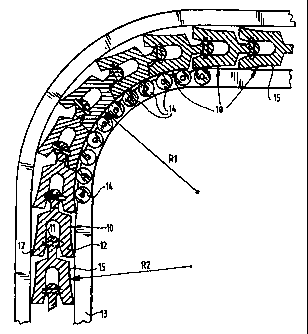
Figure 1 shows a top view in cross-section of a
second embodiment according to the invention.
Figure 2 shows a perspective view of the second
embodiment with partially cut-away parts.
Figure 3 shows a perspective view of a conveyor
device according to the invention.
Figure 1 shows a first preferred embodiment
according to the invention. Shown herein are links 10
comprising a spherical head portion 11 with a diabolo-shaped
cavity and two legs 12 connected thereto. The link chain is
guided through a guidance 13 which is provided with
rollers 14 in the bend with radius R1. Links 10 herein run
over rollers 14, whereby only a rolling resistance has to be
overcome and wear of both the guidance 13 and links 10 is
reduced.
In order to improve the running of links 10 along
rollers 14, the flanks of links 10 comprise a curved
surface 15 having a radius R2 corresponding with radius

CA 02318964 2000-07-10
~..'':::,:~:,: DESG
,'.=~:...!!>.==.=%.'~:yY.r1:j~j.:. ~.=.~=,~.,.,~~: v~v ... ..... .. . .
3
R1 of the bend. Links 10 herein lie against each other in
the bend such that they form one continuous curved
surface with radius R1, whereby links 10 can be guided
through the bend without jolting.
Figure 2 shows a perspective view of the embodiment
of figure 1. Support elements 16 are further arranged on
links 10. These support elements have on both sides a
gear wheel-like toothing 17 whereby during pivoting
parallel to the support surface the elements 16 mesh as
two toothed wheels. The central plane perpendicular MLV
to the axis H of a roller 14 is shown clearly in figure
2. The central plane perpendicular MLV to the axis H of
roller 14 passes through the link pin 18 of link 10. The
support elements hereby always extend parallel to the
support surface and the moments of force on the support
elements are always evenly balanced.
Guidance 13 consists for instance of a drawn
aluminium profile which is symmetrical relative to a
central plane parallel to the support surface, whereby
the link chain can be returned on the underside when
desired.
The flanks of the links are preferably formed by a
full surface. the links are mutually coupled with freedom
of movement, for instance as a ball hinge.
The flanks of the links moreover have a length such
that they lie against each other in the bend and form one
continuous surface.
A conveyor belt according to the invention is shown
in figure 3 wherein it is apparent that the link chain is
pivotable parallel to the support surface and in a plane
perpendicular to the conveying direction. Return of the
link chain is also shown clearly here.
WeZ- V,
.............:........ .. . .: ..: . ... .. . .

Representative Drawing
A single figure which represents the drawing illustrating the invention.
Administrative Status

2024-08-01:As part of the Next Generation Patents (NGP) transition, the Canadian Patents Database (CPD) now contains a more detailed Event History, which replicates the Event Log of our new back-office solution.

Please note that "Inactive:" events refers to events no longer in use in our new back-office solution.

For a clearer understanding of the status of the application/patent presented on this page, the site Disclaimer , as well as the definitions for Patent , Event History , Maintenance Fee  and Payment History  should be consulted.

Event History

Description Date
Inactive: Expired (new Act pat) 2019-01-12
Inactive: Office letter 2018-03-01
Inactive: Reversal of will be deemed expired status 2018-03-01
Letter Sent 2018-01-12
Grant by Issuance 2008-04-29
Inactive: Cover page published 2008-04-28
Pre-grant 2008-02-08
Inactive: Final fee received 2008-02-08
Notice of Allowance is Issued 2007-09-18
Letter Sent 2007-09-18
Notice of Allowance is Issued 2007-09-18
Inactive: Approved for allowance (AFA) 2007-08-03
Amendment Received - Voluntary Amendment 2007-06-05
Inactive: S.30(2) Rules - Examiner requisition 2007-02-20
Letter Sent 2005-10-24
Inactive: Single transfer 2005-09-14
Letter Sent 2004-01-30
Request for Examination Requirements Determined Compliant 2004-01-08
All Requirements for Examination Determined Compliant 2004-01-08
Request for Examination Received 2004-01-08
Letter Sent 2001-06-19
Inactive: Correspondence - Transfer 2001-05-15
Inactive: Courtesy letter - Evidence 2001-05-01
Inactive: Applicant deleted 2001-04-30
Inactive: Single transfer 2001-01-10
Inactive: Cover page published 2000-11-02
Inactive: Correspondence - Formalities 2000-10-31
Inactive: First IPC assigned 2000-10-25
Inactive: Courtesy letter - Evidence 2000-10-17
Inactive: Notice - National entry - No RFE 2000-10-11
Application Received - PCT 2000-10-06
Application Published (Open to Public Inspection) 1999-07-15

Abandonment History

There is no abandonment history.

Maintenance Fee

The last payment was received on 2007-12-19

Note : If the full payment has not been received on or before the date indicated, a further fee may be required which may be one of the following

  • the reinstatement fee;
  • the late payment fee; or
  • additional fee to reverse deemed expiry.

Patent fees are adjusted on the 1st of January every year. The amounts above are the current amounts if received by December 31 of the current year.
Please refer to the CIPO Patent Fees web page to see all current fee amounts.

Owners on Record

Note: Records showing the ownership history in alphabetical order.

Current Owners on Record
BOSCH REXROTH AG
Past Owners on Record
ERIC ARNOLDUS WILHELMUS ADRIANA WILLEMS
Past Owners that do not appear in the "Owners on Record" listing will appear in other documentation within the application.
Documents

To view selected files, please enter reCAPTCHA code :


To view images, click a link in the Document Description column. To download the documents, select one or more checkboxes in the first column and then click the "Download Selected in PDF format (Zip Archive)" or the "Download Selected as Single PDF" button.

List of published and non-published patent-specific documents on the CPD .

If you have any difficulty accessing content, you can call the Client Service Centre at 1-866-997-1936 or send them an e-mail at CIPO Client Service Centre.


Document
Description 
Date
(yyyy-mm-dd) 
Number of pages   Size of Image (KB) 
Representative drawing 2000-11-01 1 14
Abstract 2000-07-09 1 65
Description 2000-07-09 3 176
Drawings 2000-07-09 3 90
Claims 2000-07-09 1 49
Description 2007-06-04 4 163
Claims 2007-06-04 1 34
Representative drawing 2008-04-08 1 16
Reminder of maintenance fee due 2000-10-09 1 110
Notice of National Entry 2000-10-10 1 193
Courtesy - Certificate of registration (related document(s)) 2001-06-18 1 112
Reminder - Request for Examination 2003-09-14 1 112
Acknowledgement of Request for Examination 2004-01-29 1 174
Courtesy - Certificate of registration (related document(s)) 2005-10-23 1 106
Commissioner's Notice - Application Found Allowable 2007-09-17 1 164
Correspondence 2000-10-09 1 14
PCT 2000-07-09 14 557
Correspondence 2000-10-30 1 49
Correspondence 2001-04-30 1 20
Fees 2004-01-11 1 33
Correspondence 2008-02-07 1 39
Courtesy - Office Letter 2018-02-28 1 22