Note: Descriptions are shown in the official language in which they were submitted.
CA 02319604 2000-09-14
METHOD AND APPARATUS
FOR COATING VENTED BRAKE ROTORS
Description
This invention relates in general to the application of coatings to vented
brake
rotors, and more particularly to the application of a corrosion protection
coating to the
surfaces defining the vents of the rotors, and still more particularly to the
method and
apparatus for automatically coating the vents of brake rotors and for
precision spraying of
the exterior of the rotors.
BACKGROUND OF THE INVENTION
Heretofore, it has been well known to apply corrosion coatings to brake rotors
by
using the conventional spray, dip-spin and dip-drain coating processes.
Traditional dip-spin and dip-drain coating processes require immersing the
workpiece or part in the coating material, thereafter removing the part from
the coating
material and either spinning the part to remove the excess material or to
allow the part to
have the excess material drained from the part. Such processes normally
produce non-
uniform coating thicknesses, material striations on the rotor's outer surface
area, and
pooling of coating material in the vented areas of the rotor. Moreover,
different coating
thickness variations cannot be uniformly and consistently applied to different
surfaces and
areas of the rotors.
It is also not possible to economically mask brake rotor surface areas prior
to the
use of conventional dip drain and dip spin processes.
1
CA 02319604 2000-09-14
Accordingly, in order, to overcome the coating thickness variations of
different areas
on the rotors, as well as the pooling of material, it becomes necessary to
conduct costly
rework operations such as a secondary operation to grit blast material from
these areas after
the part is coated to remove material from areas not desired to be coated.
Moreover, the
coating problems occurring with the dip-spin and dip-drain processes often
interferes with
corrosion performance and operational functionality of the brake rotors.
Additionally, the
brake rotor appearance or aesthetics are adversely affected.
Conventional spray processes do not have the capability to assure complete and
uniform material coverage with the vented areas of a vented brake rotor which
ultimately
materially affects the corrosion protection effectiveness. Vented brake rotors
often include
forged and complex inside surface area configurations which do not easily
retain the coating
material used in conventional spray processes. Further, traditional air,
airless and
electrostatic spray processes do not have the ability to apply coating
material to all of the
rotor's vented upper, lower and side surfaces. Thus, traditional spray
processes do not
assure that the brake rotor manufacturer's corrosion protection requirements
for the vented
areas can be satisfied. Also, required functional performances cannot often be
satisfied.
Further, conventional spray processes utilizing complex spray gun and nozzle
configurations are unable to satisfactorily vary the coating thicknesses on
different surfaces
of the rotors.
Accordingly, conventional spray, dip drain and dip spin processes are unable
to
provide a cost effective high quality coating for vented brake rotors, and
particularly they
have failed to satisfy the increasing corrosion and aesthetic requirements of
the automobile
manufacturers.
2
CA 02319604 2000-09-14
SUMMARY OF THE INVENTION
The method and apparatus of the present invention overcomes problems in the
prior
known coating processes for brake rotors by uniformly coating surfaces of
vented brake
rotors and also providing different coating thicknesses for different areas
without
immersing the rotor into a coating material bath. The vent flooder and
precision spray
process of the present invention can produce different coating thicknesses in
the rotor's
vented areas, on its parking brake surfaces, on its hat areas, and other areas
as required by
the specifications of various manufacturers. The process of the present
invention eliminates
the production of material striations on the outer surface areas and the
pooling of material
within the rotor vented area, thereby improving the operational functionality
of the rotor.
The process of the present invention eliminates the need to utilize costly and
ineffective
secondary operations in order to meet the coating specifications of the
manufacturers.
Further, the present invention, by providing uniform material coverage of the
surfaces in the vents of a vented brake rotor, increases the corrosion
protection of those
vents. The process of the present invention employs several uniquely developed
components to insure coating thickness variations that can be precisely
maintained on
different outside part surface areas to meet the manufacturer's process
control
specifications. The inherent performance and quality problems created by the
conventional
processes heretofore used are eliminated by the present invention.
Although the automatic vent flooding and precision spray system of the present
invention is herein disclosed for the coating of surfaces of a vented brake
rotor, it can be
appreciated that the system may be used for a coating of other metal
workpieces,
particularly where the workpiece would include circumferentially arranged and
substantially
3
CA 02319604 2006-03-27
radially extending passageways desired to be coated with a suitable corrosion-
inhibiting
material.
Accordingly, the present invention seeks to provide an improved method and
apparatus
for coating the various surfaces of vented brake rotors or other workpieces.
Further, the present invention seeks to provide a method and apparatus for
automatic
flooding of vents in a vented brake rotor for applying a uniform coating
thickness to the
surfaces of the vents, while also recovering or reclaiming all excess
materials not adhering to
the vent surfaces.
Still further, the present invention seeks to provide a new and improved
process for
applying corrosion protection to a vented brake rotor without immersing the
brake rotor into a
coating material.
Further still, the present invention seeks to provide a manual or automatic
method and
apparatus for coating various surfaces of a vented brake rotor to provide a
coated brake rotor
with improved aesthetics corrosion performance and operational functionality.
Yet firther, the present invention seeks to provide an improved process for
providing
different coating thicknesses on a vented brake rotor.
Other aspects, features and advantages of the invention will be apparent from
the
following detailed disclosure, taken in conjunction with the accompanying
sheets of drawings,
wherein like reference numerals refer to like parts.
4
CA 02319604 2000-09-14
DESCRIPTION OF THE DRAWINGS
Fig. 1 is a perspective view of a conventional vented brake rotor;
Fig. 2 is a bottom plan view of the rotor of Fig. 1 with parts broken away to
show
vent vanes in section;
Fig. 3 is a hransverse sectional view taken substantially along line 3-3 of
Fig. 2;
Fig. 4 is a schematic flow diagram of a coating system according to the
invention
employing the madual method and apparatus for coating of a brake rotor;
Fig. 5 is a perspective view of a stand or a table for supporting and
rotatably driving
a vented brake rotor during the coating of the vent surfaces;
Fig. 6 is a somewhat enlarged further perspective view of the part of the
apparatus
shown in Fig. 5 and showing from the underside the positioning of the coating
nozzle and
air stream nozzle for applying the coating material and air stream to the
inlet ends of the
vents;
Fig. 7 is a perspective view of the cruciform-shaped fixture on which vented
brake
rotors can be mounted for rotation on the table shown in Fig. 5;
Fig. 8 is a bottom plan view of a vented brake rotor and showing in phantom
the
vanes of the rotor and also illustrating the positions of the coating and air
nozzles at the
inlet ends of the vanes and the suction nozzle at the outlet ends of the
vanes;
Fig. 9 is a generally diagrammatic side elevational and somewhat sectional
view of
the system shown in Fig. 8;
Fig. 10 is a bottom plan view of a vented disc rotor and showing a system
where the
nozzles for applying the coating material and air stream are located on the
outer periphery
of the vents while the suction nozzle is located on the inner ends of the
vents;
5
CA 02319604 2000-09-14
Fig. 11 is a diagrammatic side elevational and somewhat sectional view of the
system in Fig. 10;
Fig. 12 is a schematic flow diagram of the automatic flooder system according
to the
invention for coating the vents of the vented brake rotor and taken
transversely of the
conveyer line carrying the holders for the brake rotors;
Fig. 13 is a longitudinal diagrammatic view of the automatic vent flooder
device
according to the present invention illustrating a plurality of flooding
devices for coating
rotors moving along a conveyer and looking at the side of the conveyer
mounting the
nozzles;
Fig. 14 is a diagrammatic view of the conveyer and illustrating the device for
rotating the device for the brake rotors;
Fig. 15 is a fragmentary perspective view of the conveyer showing a partial
rotor
supporting fixture and illustrating the manner of rotating the rotor during
travel along a
conveyer;
Fig. 16 is a further diagrammatic view of the conveyer and fixtures for
holding a
plurality of rotors.
6
CA 02319604 2000-09-14
DESCRIPTION OF THE INVENTION
The present invention relates to the coating of metal surfaces and principally
the
application of a corrosion protective coating to metal surfaces of vented
brake rotors of the
type shown in Figs. 1 to 3. Such rotors include a plurality of like configured
air vents
formed by surfaces defining air flow passages. More particularly, the present
invention
provides an improved method and apparatus for coating the various surfaces of
a vented
brake rotor in order to provide uniform thickness coatings, and the variation
in thickness of
coatings at different areas to meet the specifications of the manufacturers.
The invention
includes both the manual and automatic coating of the various surfaces of a
vented brake
rotor.
It will be appreciated that the rotors will be suitably cleaned prior to the
application
of a coating material. Preferably, the rotors are chemically cleaned by the
use of
conventional equipment and cleaning materials.
The method involves the rotation of the brake rotor during the coating of the
vent
surfaces and other surfaces so as to provide a uniform coating on the
surfaces.
Accordingly, the fixture on which the rotor is mounted is connected to a drive
motor or
mechanism for rotatably driving the fixture and the rotor mounted thereon at a
desired
speed. For coating the air vents, a coating material nozzle is located at one
end of the vents
together with an air nozzle, while a suction nozzle is located at the other
end of the vents.
Preferably, the coating nozzle and the air nozzle are located at the inlet
ends of the vents,
while the suction nozzle is located at the outlet ends of the vents, although
this process may
be reversed in certain cases as desired.
7
CA 02319604 2000-09-14
The coating nozzle discharges coating material at a predetermined pressure and
flood rate to flood the vents with the coating material, while the suction
nozzle functions to
remove the excess material that does not adhere to the surfaces of the air
vents and also to
recover that excess material for further use while preventing spillover to
other surfaces of
the rotor. The air nozzle is arranged adjacent to the coating nozzle to assist
in dispersing
the coating material along the surfaces of the vents. Thus, during the
rotation of the rotor,
the coating process and recovery of the excess material coact to complete a
coating process
of the surfaces of the vents. The flow rate of the coating material, the
pressure of the air
stream, and the level of suction, together with the amount of time that the
nozzles are
operative, function to determine the thickness of the coating on the surfaces
of the vents.
Also, the speed of rotation of the rotor is coordinated with the functions of
the nozzles to
control coating thickness. The apparatus includes a stand on which the fixture
is mounted
and which would also include a motor for driving the fixture. The rotors would
be
manually mounted onto and removed from the fixture on the stand as needed to
coat and/or
further coat and cure the coatings.
The automatic method and apparatus for coating the vents of a brake rotor
includes
the utilization of a trolley conveyer having a plurality of fixtures mounted
on interconnected
trolleys on which rotors can be mounted for processing. The conveyer moves the
rotors
continuously along while adjacent to the conveyer, coating, air and suction
nozzles are
provided on fixtures that will move the nozzles into position relative to the
rotors and along
the conveyer as the rotors are advanced to perform the coating of the vents.
Following
completion of the coating of the vents, the nozzles are removed from the
positions of the
rotors and then returned to home position for applying coatings to additional
rotors being
8
CA 02319604 2000-09-14
moved along the conveyer. Moreover, the fixtures on which the rotors are
mounted as they
go through the coating station are rotated so that the rotors during the
coating process are
rotating to facilitate the proper coating of the air vents. Thereafter, the
conveyer moves the
rotors through a series of adjustably positioned spray guns for spray-coating
the exterior
surfaces of the rotors. Appropriate masking devices for masking portions of
the rotor
during spray coating are manually mounted on the rotors. Thereafter, the
rotors are
advanced through ovens for raising the temperature of the rotors and for
curing the coatings
on the rotors. It will also be appreciated that in an automated processing
line, the rotors
would first be subjected to a suitable cleaning operation, where the conveyer
would advance
the rotors through an automatic cleaning station. From the cleaning station,
the rotors
preferably would be advanced through the vent coating station, followed by
moving the
rotors through an oven to cure the coating on the vents. Thereafter, the
rotors would be
advanced along the conveyer through precision spray painting or coating
stations to paint
exterior surfaces. Masking fixtures would be manually mounted on the rotors as
needed.
The initial coating station would generally apply a base coating of material.
Then the
rotors would preferably be advanced through preheat and high heat stations to
cure the base
coating and then a cooling station. Thereafter, a top coat may be sprayed onto
the rotors to
complete the coating process.
It will be appreciated that any suitable corrosion inhibiting material may be
used to
coat the rotors. One type of suitable coating material is made and sold by
Metal Coatings
International Inc., including Dacromet 320, Dacromet 100 BL, and Dacrokote 450
coatings. Dacromet and Dacrokote are registered trademarks owned by Metal
Coatings
International Inc.
9
CA 02319604 2000-09-14
A typical vented brake rotor for purposes of illustrating the present
invention is
shown in Figs. 1 to 3 and is generally designated by the numeral 20. The brake
rotor
includes a center hub 21 sometimes called a hat for mounting to a rotatable
hub of a vehicle
about an axis of rotation drawn by the arrow 22. However, the axis of rotation
may be
opposite of that shown by the arrow 22. A pair of disc-shaped parallel spaced
apart braking
members are attached to the hub and define an outboard braking surface 23 and
an inboard
braking surface 24. A plurality of circumferentially arranged vanes 25 and 26
are
integrally formed with the disc-braking members and between the members to
separate the
members and define a plurality of circumferentially arranged and substantially
radially
extending air vents or air flow passages 27. The vanes 25 in this illustrated
brake rotor are
slightly longer than the vanes 26 although they may be of the same size.
Moreover, these
vanes extend diametrically relative to the axis of the rotor and are straight
although they
may be curved or of any other suitable shape. It should be appreciated that
the vented
brake rotor illustrated is only for purposes of generally illustrating the
method and
apparatus of the invention.
Each air flow passage includes an air inlet 28 and an air outlet 29, the air
inlets
being at the interior ends of the vanes, while the air outlets are at the
outer ends of the
vanes. Thus, the vents 27 include ends that may be defined as air inlets to
the vents during
operation on a vehicle while the other and outer ends of the vents constitute
the air outlets
29. Cooling air through the vents enhances the braking efficiency of the brake
rotor. To
enhance the life of a brake rotor it is therefore important to have a
corrosion protection on
the surfaces forming and defining the vents. It will be appreciated that the
one-piece brake
CA 02319604 2000-09-14
rotor may be constructed from a one-piece casting of iron, aluminum or other
suitable
metal, as is conventional for brake rotors.
While the present invention embraces both a manual method and apparatus for
coating brake rotors, it also embraces an automatic method and apparatus for
coating brake
rotors. In both arrangements or systems, the method and apparatus for coating
the vents of
the rotors utilize a coating nozzle, a suction nozzle, an optional air-stream
nozzle, and
means for rotating the rotor during the coating operation.
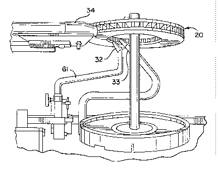
Referring now to Figs. 8, 9, 10 and 11, a diagrammatic showing of how the
coating, air and suction nozzles may be arranged relative to the rotor is
illustrated. In Figs.
8 and 9, a coating nozzle 32 is positioned to direct a stream of coating
material toward the
inlet ends 28 of the vents or air passages. Similarly, an air flow nozzle 33
is positioned
adjacent to the coating nozzles for directing a stream of air toward the inlet
ends of the
vents. At the same time, a suction nozzle 34 is positioned at the outlet ends
of the vents for
applying a suction force to the outlet ends to assist in moving the coating
material through
the vents and also to recover the excess coating material not applied to the
surfaces of the
vents, thereby avoiding spillover to other surfaces of the rotor. While the
air nozzle 32
may be optionally used in certain applications, preferably it is used at all
times during the
application of coating material to the vents. It will be understood that the
coating material
will be directed under pressure toward the vents and the end of the nozzle
will be suitably
positioned at the inlet ends of the vents to flood the vents with coating
material. Further, it
will be appreciated that the air nozzles will provide compressed air of a
desired value in
order to provide the optimum assistance in flooding the vents with the coating
material.
Finally, it will be appreciated that the suction nozzles will have a level of
suction force such
11
CA 02319604 2000-09-14
as to provide the assistance in moving the coating material through the vents
and recovering
the excess material which can be later used again. Thus, the coating, air and
suction
nozzles coact together to not only uniformly coat the interior surfaces of the
vents but also
to facilitate the recovery of excess material that is not applied to the
surfaces as it moves
through the vents. Further, the speed of rotation of the rotor is controlled
in accordance
with the conditions needed in order to provide the desired coating thickness
in the vent
areas.
While it is preferred that the coating and air nozzles be positioned at the
interior of
the rotors and pointed in a direction toward the inlets of the air vents, it
can be appreciated
that for certain applications it may be desirable to place the coating and air
nozzles to direct
their coating material and air stream in toward the outlet ends of the vents,
as shown by the
embodiment of Figs. 10 and 11. In this embodiment, the coating material nozzle
32a and
the air nozzle 33a are disposed at the outer periphery of the rotor to direct
the coating
material and the air stream toward the outlet ends 29 of the vents. In this
embodiment, the
suction nozzle 34a is then mounted at the inlet ends 28 of the vents. In all
cases, the
suction nozzle or nozzles will be positioned as close as possible to the rotor
vent inlets or
outlets without interfering with the rotation of the rotors.
The flow diagram showing the system of applying the coating material is
illustrated
in Fig. 4 for the embodiment of Figs. 8 and 9 wherein the coating material
nozzle 32 is
connected through suitable lines to a material feed system 38. It will also be
noted that the
air nozzle 33 for providing the air stream toward the inlet and the vents is
connected
through a suitable line to an air compressor 39. The suction nozzle 34 is
connected through
a suitable line to a material reclaim system 40 which in turn is connected to
a vacuum
12
CA 02319604 2000-09-14
system 41 for reclaiming and recovering the excess coating material not used
during the
flooding of the air vents of the rotor. Additionally, a turn line 42 is
provided from the
material reclaim system to feed the reclaim material back into the material
feed system 38.
The vented brake rotor 20 is diagrammatically illustrated as being mounted on
a
fixture or spindle 44 that is connected through suitable gearing to a variable
speed drive 45
for rotatably driving the spindle and the rotor during the coating process.
The variable
speed drive is controlled by a control panel 46 to provided the desired speed
of the rotor
during any coating operation.
Referring to Figs. 5 to 7, an apparatus for mounting and driving a vented disc
rotor
to accomplish the manual method of coating the vents is illustrated, which
includes a table
or stand 48 having a plurality of legs 49 to support the stand on the floor.
The spindle 44 is
suitably rotatably supported on the table 48 and extends upwardly from the
table and
includes a fixture 52 of a cruciform shape. The cruciform elements are carried
on a disc 53
such that the cruciform elements are received in the opening 30 of the disc
when the disc is
mounted on top of the fixture 52 and resting against the disc 53. A fixture of
any suitable
form may be provided, and it may depend on the form of the rotor. Thus, the
brake rotor
can easily be mounted onto and be removed from the fixture 52 and held in
proper place
during the time that it is undergoing the coating of the surfaces defining the
vents. The
spindle or shaft 44 extends below the table 48 and includes a sprocket 55
aligned with a
sprocket 56 and interconnected by a chain 57. The sprocket 56 is mounted on
the shaft of a
variable speed motor 58 supported below the table 48. Thus, the variable speed
motor 58
drives the sprocket 56 and through the endless chain 57 the sprocket 55 on the
spindle or
shaft 44 on which the fixture 52 is mounted for receiving a vented brake
rotor. The control
13
CA 02319604 2000-09-14
59 is provided on top of the table 48 in order to control the speed of the
variable speed
motor 58 and the speed of the rotor.
The material feed or coating nozzle 32 is connected to a line 61 and in turn
to a
manifold 62 mountable on the table in a suitable manner for adjustment
purposes so that it
may assist in adjusting the position of the material feed nozzle 32 relative
to the particular
vented disc rotor being coated. Similarly, the air nozzle 33 is connected to
an air line 63
and which in turn would be connected to the air compressor. The air line would
be such
that it could suitably support the air nozzle in position as shown,
particularly in Fig. 6.
The suction nozzle 34 is supported by an arm 64 that is suitably carried on an
adjustable bracket 65 for adjustably positioning the suction nozzle 34
adjacent the perimeter
of the vented disc rotor. A plurality of suction lines 66 extends from the
suction nozzle 34
and to the material reclaim system 40 and the vacuum system 41. Once the
positions of the
nozzles are set for a given rotor, they need not be moved during the coating
of any number
of rotors.
A further control 67 is provided adjacent the control 59 for the operator to
use in
connection with the controlling the material feed, suction and air nozzles.
Accordingly, the
operator would manually mount a vented disc rotor onto the fixture 52 and
properly
position the coating material nozzle and the air nozzle as well as the suction
nozzle and then
operate the controls 59 and 67 to rotate the rotor and then to apply the
coating material
through the coating nozzle as well as the air stream through the air nozzle
and also to allow
the suction nozzle to recover the excess material not applied to the surfaces
of the air vents
of the rotor. At the conclusion of the coating process, the operator would
remove the
vented rotor from the fixture and then transfer the rotor to another fixture
for purposes of
14
CA 02319604 2000-09-14
applying coating material to the exterior surfaces as desired before the rotor
would be
subjected to heat for curing the coating material on the rotor.
The automatic vent flooder of the present invention is shown in Figs. 12 to 16
and
serves to flood the rotor's internal air vent surface area with coating
material as the brake
rotor is rotated along a motorized conveyer. A plurality of sets of rotors is
supported on
fixtures carried on the qonveyer, and when a set of rotors is in position
parallel to the
flooding apparatus along the conveyer, the apparatus simultaneously injects
and removes
coating material to and from the rotor's internal vented surface areas while
coating the air
vent surfaces. It will be appreciated that the material flowing into an air
vent or
passageway is uniformly dispersed along a vent's inside surface area' by
applying air
pressure to the material while it fills the vent's inner cavities. During this
time material is
extracted from the vent cavities by a suction nozzle driven by a vacuum
system.
Accordingly, the air vents of the rotor are then uniformly and completely
coated with
material while preventing material spillage from occurring on the brake
rotor's external
surface area. The thickness of this coating may be on the order of 5 to 8 mils
(0.127 to
0.203 mm) depending on the surface finish and the specifications of the user.
This
produces an economical and more efficient use of the coating material.
Inasmuch as a plurality of rotors is arranged in stacked relation or rather in
vertically spaced apart relation, a plurality of flooding devices is used for
simultaneously
coating the air vents of a plurality of rotors. It will be appreciated that
the material flow,
that is, the rate of coating material flowing from the coating nozzle, the
time period of the
material flow, the air pressure and the vacuum suction, together with the
rotational speed of
the brake rotor, can be varied independently to accommodate vent sizes and
configurations,
CA 02319604 2000-09-14
and to obtain the desired coating thickness on the vent surfaces of the rotor.
Accordingly,
precise and complete material coverage within the vents is assured. The
coating nozzle
includes a discharge opening that will produce a stream of coating material,
preferably like
a ribbon.
Thereafter the automatic process uses precision control spray equipment to
coat the
brake rotor's outside surface areas. The thickness of exterior surfaces may be
on the order
of 2 to 4 mils (0.051 to 0.012 mm). This precision control equipment permits
the
application of varying thicknesses of coating material at varying locations on
the brake
rotor's outside surface areas. For example, it is possible to coat the rotor's
hub or hat area
with a material of different thickness than that of the braking surface area.
The automatic
process permits the use of fixture masks that may be easily disposed on the
rotors to
prevent the coating of outside surface areas such as the parking brake surface
area where
material coverage could potentially impact the brake rotor's operational
functionality, or to
mask other surfaces.
Following the spray coating of the outside surface areas of the rotors, the
rotors are
conveyed through an oven to provide sufficient heat to the rotors and the
coating to cure the
coatings. The oven or ovens are capable of curing different coating materials
used on brake
rotors of varying size and weight. For example, the ovens are capable of
heating the rotors
to a temperature of between 610 and 650 C. as the rotors pass through over a
time period
of ten to fifteen minutes in order to obtain the proper curing of the coating
material.
The automated conveyer and part rotater, shown in Figs. 12 to 16, includes a
plurality of trolleys 70 interconnected together and movably guided along a
track 71.
While each trolley is shown to include a pair of rotatably supported sprockets
72 and 73, it
16
CA 02319604 2000-09-14
will be appreciated that each trolley may be provided only with a single
rotatably supported
sprocket if desired. The sprocket 72 on each trolley has supported thereon an
upstanding
vertical shaft 74 carrying a plurality of fixture pins 75 for receiving and
supporting a
plurality of vented brake rotors 20 in superposed spaced apart relation. The
sprocket 72,
when connected to the fixture pins 75 and the shaft 74, rotate the fixture pin
and fixtures in
order to rotate the workpieces or parts mounted on the fixtures as they move
through
various steps in the coating process. It will be appreciated that the speed of
the conveyer
can be precisely timed to increase or decrease the number of cars that can be
processed
over a given period of time. Once the rotors are loaded onto the conveyer,
there is no
manual labor involved until the parts are unloaded and inspected before a
shipment. At
various stations along the conveyer, part rotaters are included for the
purpose of rotating
the spindle or fixture pins on which the rotors are mounted during the
application of a
coating. One of the rotater apparatus is provided to rotate the fixture and
the brake rotors
while the flooder apparatus applies coating material to the vents of the
rotors and another
rotater apparatus is located at a station where the fixtures and rotaters can
be rotated as the
outside surface areas of the rotors are precision spray coated. Each part
rotater is
independently controlled and to provide the proper speed of the rotor. By
adjusting the
speed of the conveyer the rotational speed of the fixture pin and parts may be
changed.
Further, adjustments can be used to vary the material coverage of the rotor's
surface areas
during both the vent flooding stage and the precision spray stage of the
process.
A driven chain 77 located alongside of the conveyer is provided to engage the
fixture pin's sprockets 72 to rotate the rotors on the fixtures while a
coating operation is
being performed. The chain 77 is driven around longitudinally spaced apart
sprockets 78
17
CA 02319604 2000-09-14
and 79 by a suitable motor such as a motor 80 shown in Fig. 14. So as the
conveyer with
the rotatable fixture pins and rotors are advanced along the part rotater of
the chain 77, the
rotors will be rotated at a desired speed. The speed of the chain may be
increased or
decreased, as well as the speed of the conveyer carrying the fixture pins, in
order to obtain
the proper speed of rotation of the rotors.
At the station where the part rotater is located to rotate the fixture on
which the
rotors are mounted the vent flooder device is mounted adjacent to the conveyer
to
accomplish the flooding of the vents with the coating material as previously
described. The
vent flooder device is generally indicated by the numeral 82 and shown in
Figs. 12 and 13.
This vent flooder device 82 is mounted adjacent to the automatic conveyer and
automatic
part rotater and automatically tracks the rotors on the conveyer through a
suitable control
system. It is synchronized with the automatic conveyer to engage the various
vent flooder
holder devices after a predetermined number of rotors is recognized. The vent
flooder is
employed to apply suitable coating material to the inside of each rotor's
vented areas.
The automatic vent flooder operates to first move each vent flooder device
holder
into position either beneath a rotor or above a rotor, depending upon location
of the rotor
and its vented areas. This positioning will only occur after a set number of
rotors has
moved into position along where the vent flooding apparatus is located. Once
this position
is completed, each vent flooder device holder engages a vent flooding device
which
continues to follow the rotors along the automatic conveyer path until the
vent flooding
device operations are complete. Following the completion of the vent flooding
operations,
the vent flooder holding devices are then retracted or moved away from the
rotors and the
conveyer line and thereafter repositioned to their original home or starting
position along
18
CA 02319604 2000-09-14
the conveyer line before engaging and performing functions on the next set of
rotors. All
movements toward and away from the rotors and in parallel with the conveyer
are
controlled by using air cylinders, ball screws, slide and microprocessor
components.
The vent flooder device 82, as shown in Figs. 12 and 13, is mounted on a table
84
supported on the floor by a suitable frame 85. The table includes a set of
slide rails 86
having attached thereto a plurality of saddles 87. The vent flooder device
shown in the
drawings in Fig. 13 includes four saddles 87 and three vent flooder device
holders 88 per
saddle, which gives the device the capability of simultaneously vent flooding
12 rotors. It
can be appreciated that by adding the slide to the slide rail's length and
increasing the
=
number ofsaddle attachments and increasing the number of part flooder device
holders, it
is possible to increase the number of parts that can be flooded
simultaneously. It is also
possible to increase the number of vent flooder device holders if additional
rotors are
mounted vertically on a fixture. Each vent flooder device holder 88 is
automatically
programmed to move up and down independently along the frame of the device and
the
length of travel is controlled by an air cylinder. This allows each vent
flooder device
holder and its associated devices to be independently and precisely positioned
to meet each
rotor's coating requirements. Speed and travel path of the saddles 87 and the
vent flooder
holders are controlled by a ball screw drive that is synchronized with the
conveyer speed
and the rotors.
Each vent flooder device holder 88 includes a material feed nozzle 32
connected by
flexible tubing to an automated feed system 38a. A pump 90 is located within
the material
feed system 38a to deliver the material from the system container of the
tubing to the feed
nozzle 32 at a desired flow rate. The size and orientation of the nozzle is
flexible so that it
19
CA 02319604 2000-09-14
can be properly positioned to provide the desired performance. As illustrated
in the
schematic diagram of Fig. 12, a plurality of feed nozzles is connected to the
single material
feed system 38a. It should also be appreciated that different sizes and shapes
of nozzles can
be used to support sizes and shapes of vented areas and also to control the
amount of
material to be dispersed to the vented areas. Further, the pump speeds can be
regulated to
control the amount of material being applied through the nozzles to the vents.
The compressed air nozzle 33 is positioned adjacent to the material feed
nozzle 32
and serves to force air pressure onto the material as it enters the vented
areas of the rotors.
This air tends to disperse the material to the air vent's upper, lower and
side surface areas
and through to the vent's opening on the outer side. It is also possible to
use multiple
compressed air nozzles and vary the air pressure to each nozzle. Further, the
use of
different size and shapes of different nozzles will assure that consistent
material dispersion,
vent coverage, and pass-through material will be provided.
A vacuum nozzle 34 draws materials from the vents, controls the amount of
material
that is exiting the vented areas. This suction action also spreads the
material into the vent's
upper, lower and side surface cavities. After any excess material drawn from
the vents is
reclaimed and recycled to the material feed container 40a. It will be
appreciated that the
number of suction nozzles may be varied as well as the sizes and shapes to
provide the
proper material dispersion and vent coverage for the air vents. Thus, the
sizes and shapes
of the nozzles, coupled with precise control over the amount of vacuum power,
guarantees
that the vent coverage will be provided without spill-over to the external
surface areas of
the vented rotor.
CA 02319604 2000-09-14
The combined actions of the material feed nozzle, the compressed air nozzle,
and
the suction nozzles ensure complete and uniform coverage of the material
within the rotor
vented areas, while also preventing the material from pooling inside the
vented areas and
from material spilling over the rotor's external surface areas.
It will be further appreciated that the vent flooder holder devices 88 are
controlled
by the use of electronic controls and external sensors. A microprocessor is
connected to
different external sensors to determine the vertical and horizontal movement
of a vent
flooder device holder before commencing the operation of the material coating
air stream
and suction devices and to regulate the start and stop of the material to the
air flow of a
brake rotor's vented areas. Additionally, the sensors control the velocity and
inches of
water drawn by the material vacuum suction system 41a as well as determining
whether a
rotor is loaded on a particular holder before a vent flooder holder device is
placed into
operation.
Further, it should be appreciated that all process parameters are adjustable
depending upon the coating materials used and the specifications required by
the
manufacturer for a particular vented rotor configuration. So any size brake
rotor may be
accommodated with a particular coating specification of the manufacturer.
While not shown, the precision spray apparatus would include a set of
conventional
spray guns that can be appropriately positioned and controlled to provide
precise coating
thicknesses on the exterior surfaces of the vented rotors. Conventional spray
guns are
mounted so that they may be quickly adjusted for different rotor outside
surface area
coating thickness specifications and locations. Coating materials are fed to
the spray guns
using a single container feed system that insures uniform spray pattern
consistency.
21
CA 02319604 2000-09-14
In view of the foregoing, a new and improved method and apparatus for applying
corrosion protective materials to vented brake rotors and other parts is
provided by the
invention to assure uniform coating thicknesses and to maximize the efficiency
of using
coating materials.
It will be understood that modifications and variations may be effected
without
departing from the scope of the novel concepts of the present invention, but
it is understood
that this application is to be limited only by the scope of the appended
claims.
22