Language selection

Search

Patent 2319607 Summary

Third-party information liability

Some of the information on this Web page has been provided by external sources. The Government of Canada is not responsible for the accuracy, reliability or currency of the information supplied by external sources. Users wishing to rely upon this information should consult directly with the source of the information. Content provided by external sources is not subject to official languages, privacy and accessibility requirements.

Claims and Abstract availability

Any discrepancies in the text and image of the Claims and Abstract are due to differing posting times. Text of the Claims and Abstract are posted:

  • At the time the application is open to public inspection;
  • At the time of issue of the patent (grant).
(12) Patent: (11) CA 2319607
(54) English Title: A ROTO-DYNAMIC HIGH PRESSURE MACHINE
(54) French Title: MACHINE CENTRIFUGE HAUTE PRESSION
Status: Expired and beyond the Period of Reversal
Bibliographic Data
(51) International Patent Classification (IPC):
  • F04D 1/06 (2006.01)
  • F04D 17/12 (2006.01)
  • F04D 29/22 (2006.01)
(72) Inventors :
  • ARBEUS, ULF (Sweden)
(73) Owners :
  • ITT MANUFACTURING ENTERPRISES, INC.
(71) Applicants :
  • ITT MANUFACTURING ENTERPRISES, INC. (United States of America)
(74) Agent: SMART & BIGGAR LP
(74) Associate agent:
(45) Issued: 2003-11-04
(22) Filed Date: 2000-09-14
(41) Open to Public Inspection: 2001-03-15
Examination requested: 2000-09-14
Availability of licence: N/A
Dedicated to the Public: N/A
(25) Language of filing: English

Patent Cooperation Treaty (PCT): No

(30) Application Priority Data:
Application No. Country/Territory Date
9903278-1 (Sweden) 1999-09-15

Abstracts

English Abstract


An improved pump or compressor of the centrifugal
type is provided, which has an impeller surrounded by a
housing and having a disk, a first plurality of vanes
provided near the disk, cover disks provided about the edges
of the vanes, and a second plurality of vanes provided on
the outwardly directed sides of the cover disks. Two
pressure steps are created by the first plurality of vanes,
each side of the disk and the cover disks. Two additional
pressure steps are created by the second plurality of vanes,
the cover disks, and pump housing walls that are located
adjacently to the second plurality of vanes. Single or
multiple flow conduits are arranged among the various inlets
and outlets of the pressure steps, such that a fluid flows
through the various pressure steps, with the last pressure
step being closest to a motor unit and an outlet connected
to the last pressure step being on the same side and facing
in the same direction as an inlet. Demands for higher
efficiencies, improved compactness and a simpler, more
symmetrical design are met by this configuration.


Claims

Note: Claims are shown in the official language in which they were submitted.

7
CLAIMS:
1. A pump or compressor of a centrifugal type for
providing high pressures, comprising:
a rotary shaft;
a motor connected to the shaft;
an impeller connected to the shaft and surrounded
by a housing, where the impeller comprises a circular disk
connected to a hub;
a first set of two or more vanes provided on each
side of the circular disk;
cover disks provided on the edges of the first set
of vanes; and
a second set of two or more vanes provided on the
outwardly directed sides of the cover disks, where two
pressure steps are formed by the first set of vanes, each
side of the circular disk and the cover disks, and an
additional two pressure steps are formed by the second set
of vanes, the cover disks, and a set of pump housing walls
located adjacently to the second set of vanes, with single
or multiple flow conduits arranged between the outlet of a
first pressure step and the inlet of a second pressure step,
between the outlet of the second pressure step and the inlet
of a third pressure step and between the outlet of the third
pressure step and the inlet of a fourth pressure step, and
where a last pressure step, which has a highest output
pressure, is closer to the motor than any other pressure
step and is connected with an outlet, which is located on
the same side of the pump or compressor as an inlet and
faces in the same direction as the inlet.

Description

Note: Descriptions are shown in the official language in which they were submitted.


CA 02319607 2003-04-16
74156-11
1
A ROTO-DYNAMIC HIGH-PRESSURE MACHINE.
FIELD OF THE INVENTION
The invention relates to a high-pressure machine,
and more particularly, to a pump for liquids or a compressor
for obtaining a media transport, including gaseous media,
under high pressure.
BACKGROUND OF THE INVENTION
When pumping liquids to high levels where
consequent high pressures are required, a pump of the
centrifugal type is preferred. Such a pump comprises a pump
impeller on a rotating shaft, such an impeller being
designed with a hub and a circular disk provided with one or
several impeller vanes. The liquid enters in an axial
direction in the center and leaves the impeller at the
periphery. A pump housing surrounding the impeller
transforms the kinetic energy to pressure energy, thereby
raising the transport to a higher level.
At higher heads, it is common to use pumps with
high rotation speeds and relatively small diameters. It is
also possible to connect a number of pumps in series by
connecting the outlet from a first step to the inlet in a
second step and so on. An example is shown in EP-A-355781,
where five steps are connected in series.
When a certain operation point at a certain
rotation speed is chosen, it can be an advantage to use
several steps, as the pump impellers can operate at rotation
speeds which are superior in terms of efficiency. This
increase of efficiency is mainly related to the fact that
the friction losses at the back sides of the impeller hubs,
as a part of the total losses, decrease. However, linking

CA 02319607 2003-04-16
74156-11
2
losses between the steps are added. A further disadvantage
is that the relatively complicated design means that service
and maintenance become complicated and in addition, long
shafts bring about increased mechanical stress.
Another way to obtain high pump heads is to
connect two identical pressure steps in series as is shown
in US-A-958 765 and DE-353 698. The pump impellers are here
arranged mirror-inverted, but have in other respects
conventional designs. US-A-2 136 939 discloses a pump with
two pressure steps having a common hub disk, thereby
obtaining a reduction of the disk losses. Both of these
solutions, however, have in common the problem that they
only allow two pressure steps. Therefore, these
conventional solutions are not always sufficient in terms of
obtaining the desired pump head.
What is needed, therefore, is a pump or compressor
having more than two pressure steps that can achieve a high
efficiency, while minimizing linking losses and avoiding
complicated designs.
2 0 SUI~iARY OF THE INVENTION
According to the invention there is provided a
pump or compressor of a centrifugal type for providing high
pressures, comprising: a rotary shaft; a motor connected to
the shaft; an impeller connected to the shaft and surrounded
by a housing, where the impeller comprises a circular disk
connected to a hub; a first set of two or more vanes
provided on each side of the circular disk; cover disks
provided on the edges of the first set of vanes; and a
second set of two or more vanes provided on the outwardly
directed sides of the cover disks, where two pressure steps
are formed by the first set of vanes, each side of the
circular disk and the cover disks, and an

CA 02319607 2003-04-16
74156-11
3
additional two pressure steps are formed by the second set
of vanes, the cover disks, and a set of pump housing walls
located adjacently to the second set of vanes, with single
or multiple flow conduits arranged between the outlet of a
first pressure step and the inlet of a second pressure step,
between the outlet of the second pressure step and the inlet
of a third pressure step and between the outlet of the third
pressure step and the inlet of a fourth pressure step, and
where a last pressure step, which has a highest output
pressure, is closer to the motor than any other pressure
step and is connected with an outlet, which is located on
the same side of the pump or compressor as an inlet and
faces in the same direction as the inlet.
In accordance with the invention, a pump or a
compressor having more than two pressure steps is provided,
which has a very high efficiency due to the minimization of
disk losses. The device according to the invention also
provides a design that is very compact, easy to mount and
adaptable with regard to axial forces and seal pressures.
The present invention, by allowing more than two
pressure steps, permits the achievement of higher pump
heads. By having a common hub disk, disk losses are
minimized and the use of multiple steps results in higher
efficiencies, as described above. Additionally, by having a
compact, easy to mount design, conventional problems such as
complicated service and maintenance, linking losses between
steps, and increased mechanical stresses due to long shafts
are minimized or avoided.
BRIEF DESCRIPTION OF THE DRAWINGS
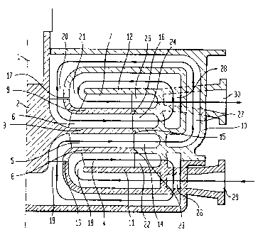
Figure 1 shows a sectional view of the pump of an
embodiment of the subject invention; and

CA 02319607 2003-04-16
74156-11
4
Figure 2 shows the sectional view of Figure 1
inserted in a sectional view of a submersible pump.
DETAILED DESCRIPTION OF THE INVENTION
In the drawings, 1 stands for a rotary shaft and 2
is a pump impeller hub having a disk, 3. 4, 5, 6, and 7 are
impeller vanes, 8 and 9 are cover disks and l0 is a part of
a pump housing comprising walls 11 and 12 opposing the
impeller. 13, 14, 15, 16 and 17 symbolize seals, and 18,
19, 20 and 21 stand for inlets to the pressure steps. 22,
23, 24 and 25 stand for diffusers in the pump steps. 26, 27
and 28 stand for flow conduits and 29 and 30 stand for the
inlet and the outlet, respectively, for the pump. 31 stands
for the motor unit.
According to the invention, the high-pressure pump
comprises a pump housing 10 within which a rotating hub 2
with a connected disk 3 is arranged. The disk 3 is on each
side provided with vanes 5 and 6 respectively.
Each group of vanes 5 and 6 are provided with a
cover disk 8 and 9, respectively, thereby creating a double-
2o sided closed pump impeller. The cover disks 8 and 9 are on
their respective opposite sides provided with additional
vanes which form another double sided pump impeller together
with the pump housing walls 11 and 12, respectively. In
this way, a four-step pump impeller is created having two
closed and two open channels.
The pump operates in the following way: the
liquid is sucked in through the inlet 29 and flows to the
inlet 18 of the first pressure step. This step is formed by
the vanes 4, the cover disk 8 and the pump housing wall 11.
A flow conduit 26 goes from the diffuser 22 of said first
pressure step to the inlet 19 of a second pressure step,

CA 02319607 2003-04-16
74156-11
said second step being formed by the vanes 5, the underside
of the hub disk 3 and the cover disk 8. A second flow
conduit 27 goes from the diffuser 23 of said second pressure
step to the inlet 20 of a third pressure step, said third
5 step being formed by the vanes 6, the upside of the hub disk
3 and the cover disk 9. A third flow conduit 28 goes from
the diffuser 24 of said third pressure step to the inlet 21
of a fourth pressure step, said fourth step being formed by
the vanes 7, the cover disk 9 and the pump housing wall 12.
Finally, the liquid leaves the pump via the diffuser 25 of
the fourth pressure step through the outlet 30.
The pump according to the present invention
provides a number of advantages when compared with
conventional high-pressure pumps having one or several
pressure steps.
The efficiency is very high because multiple
pressure steps bring about more favorable specific rotation
speeds and considerable reductions in disk losses.
As shown in Figure 1, the last pressure step,
having the highest output pressure, is located adjacently to
the motor unit 31 and closer to the motor unit 31 than any
other pressure step. Additionally, the outlet 30, connected
to the last pressure step, is located on the same side of
the device as the inlet 29 and faces in the same direction
as the inlet 29. This design, where both the inlet 29 and
the outlet 30 are located on the same side of the device and
also near the motor unit, results in a very compact,
substantially symmetrical pump. This highly compact,
symmetrical design results in greater opportunities to
reduce axial forces, as well as seal pressures, when
compared with conventional devices. Problems such as
complicated service and maintenance, linking losses between

CA 02319607 2003-04-16
74156-11
6
steps, and increased mechanical stresses due to long shafts
are also minimized. The simple design also results in a
pump that is much easier to mount than conventional multi-
step pumps.
In the embodiment of the invention that is
described above, the importance of minimizing the pressure
difference between two adjacent pressure steps has been
stressed. If it is more important to minimize the axial
forces, another order between the steps might be preferable.
It is anticipated by the invention that various such mutual
orders of the pressure steps may be employed. The scope of
the invention also includes an embodiment where all of the
channels in the impeller are closed.
As previously mentioned, the invention is not
limited to pumps for liquids, but is also applicable for the
pressurizing of gaseous media.

Representative Drawing
A single figure which represents the drawing illustrating the invention.
Administrative Status

2024-08-01:As part of the Next Generation Patents (NGP) transition, the Canadian Patents Database (CPD) now contains a more detailed Event History, which replicates the Event Log of our new back-office solution.

Please note that "Inactive:" events refers to events no longer in use in our new back-office solution.

For a clearer understanding of the status of the application/patent presented on this page, the site Disclaimer , as well as the definitions for Patent , Event History , Maintenance Fee  and Payment History  should be consulted.

Event History

Description Date
Time Limit for Reversal Expired 2008-09-15
Letter Sent 2007-09-14
Inactive: IPC from MCD 2006-03-12
Grant by Issuance 2003-11-04
Inactive: Cover page published 2003-11-03
Pre-grant 2003-08-19
Inactive: Final fee received 2003-08-19
Notice of Allowance is Issued 2003-06-02
Letter Sent 2003-06-02
Notice of Allowance is Issued 2003-06-02
Inactive: Approved for allowance (AFA) 2003-05-23
Amendment Received - Voluntary Amendment 2003-04-16
Inactive: S.30(2) Rules - Examiner requisition 2003-01-16
Amendment Received - Voluntary Amendment 2002-07-09
Application Published (Open to Public Inspection) 2001-03-15
Inactive: Cover page published 2001-03-14
Inactive: First IPC assigned 2000-11-23
Inactive: Filing certificate - RFE (English) 2000-10-17
Filing Requirements Determined Compliant 2000-10-17
Letter Sent 2000-10-17
Application Received - Regular National 2000-10-16
Request for Examination Requirements Determined Compliant 2000-09-14
All Requirements for Examination Determined Compliant 2000-09-14

Abandonment History

There is no abandonment history.

Maintenance Fee

The last payment was received on 2003-04-22

Note : If the full payment has not been received on or before the date indicated, a further fee may be required which may be one of the following

  • the reinstatement fee;
  • the late payment fee; or
  • additional fee to reverse deemed expiry.

Please refer to the CIPO Patent Fees web page to see all current fee amounts.

Fee History

Fee Type Anniversary Year Due Date Paid Date
Application fee - standard 2000-09-14
Registration of a document 2000-09-14
Request for examination - standard 2000-09-14
MF (application, 2nd anniv.) - standard 02 2002-09-16 2002-09-16
MF (application, 3rd anniv.) - standard 03 2003-09-15 2003-04-22
Final fee - standard 2003-08-19
MF (patent, 4th anniv.) - standard 2004-09-14 2004-08-30
MF (patent, 5th anniv.) - standard 2005-09-14 2005-08-30
MF (patent, 6th anniv.) - standard 2006-09-14 2006-08-21
Owners on Record

Note: Records showing the ownership history in alphabetical order.

Current Owners on Record
ITT MANUFACTURING ENTERPRISES, INC.
Past Owners on Record
ULF ARBEUS
Past Owners that do not appear in the "Owners on Record" listing will appear in other documentation within the application.
Documents

To view selected files, please enter reCAPTCHA code :


To view images, click a link in the Document Description column. To download the documents, select one or more checkboxes in the first column and then click the "Download Selected in PDF format (Zip Archive)" or the "Download Selected as Single PDF" button.

List of published and non-published patent-specific documents on the CPD .

If you have any difficulty accessing content, you can call the Client Service Centre at 1-866-997-1936 or send them an e-mail at CIPO Client Service Centre.


Document
Description 
Date
(yyyy-mm-dd) 
Number of pages   Size of Image (KB) 
Representative drawing 2001-03-06 1 21
Abstract 2003-04-16 1 32
Description 2003-04-16 6 258
Claims 2003-04-16 1 38
Representative drawing 2003-09-30 1 27
Cover Page 2003-09-30 2 64
Cover Page 2001-03-06 1 43
Drawings 2002-07-09 2 44
Abstract 2000-09-14 1 16
Description 2000-09-14 4 170
Claims 2000-09-14 1 50
Drawings 2000-09-14 2 53
Courtesy - Certificate of registration (related document(s)) 2000-10-17 1 120
Filing Certificate (English) 2000-10-17 1 163
Reminder of maintenance fee due 2002-05-15 1 111
Commissioner's Notice - Application Found Allowable 2003-06-02 1 160
Maintenance Fee Notice 2007-10-29 1 171
Correspondence 2003-08-19 1 46
Fees 2002-09-16 1 39