Note: Descriptions are shown in the official language in which they were submitted.
CA 02319615 2000-08-02
WO 99/39641 PGT/IB99/00377
1
ANNULAR ARRAY ULTRASOUND CATHETER
BACKGROUND OF THE INVENTION
The present invention relates generally to the field
of medical catheters, and in particular, to ultrasonic imaging
medical catheters.
In recent years, the use of ultrasound systems for
medical diagnostics has continued to grow. Ultrasonic systems
are used in a plethora of medical fields and in a wide-ranging
number of diagnostic areas. As the desire to use ultrasonic
imaging systems has grown, so has the level of sophistication
of those systems.
To assist physicians and staff in performing
diagnostic and therapeutic procedures, a number of ultrasonic
imaging systems have been designed for use with catheters. In
general, these systems comprise a single transducer element,
frequently made of piezoelectric material, attached to the
distal portion of an imaging catheter. The imaging catheter
is inserted into the patient and the transducer is positioned
within the patient to image a desired region of the patient's
anatomy.
Such catheters typically operate by sending an
electrical signal or excitation pulse to the transducer. The
transducer converts the electrical energy into mechanical
energy, which propagates into a patient's surrounding body
tissues as an ultrasonic wave. The frequency of the emitted
ultrasonic waves are a function of the resonant frequency of
the transducer element and the frequency content of the
excitation pulse. The ultrasonic waves are reflected back to
the transducer as reflected signals or echoes, which the
transducer converts into an electrical signal. This
electrical signal is used to produce an image of the patient's
anatomy.
By operating with a single transducer, however, the
images produced are limited to a single two-dimensional plane.
CA 02319615 2000-08-02
WO 99139641 PCT/IB99/00377
2
As a result, the transducer must be moved within the patient
- to produce images over a larger area. Additionally, since the
single transducer element has only one resonant frequency, the
focusing capability of single transducer imaging catheters is
limited. The frequency of emitted sound waves, which vis a
function of the resonant frequency and bandwidth of the
transducer element and the frequency content of the excitation
pulse, can only be varied by varying the excitation pulse
frequency. As a result, the ability of a single transducer
element to be focused at different depths into the surrounding
tissue is limited.
It would be desirable, therefore, to provide an
imaging catheter system capable of providing high quality
ultrasound images. It is further desirable to provide for
focusing in more than one plane to provide improved lateral
resolution. It is also desirable to provide the capability to
produce and receive multiple ultrasonic signals. It is
further desirable to provide such a system for use with an
ultrasonic imaging catheter.
SUMMARY OF THE INVENTION
The present invention provides for catheter systems
and methods of their use. In one embodiment, the invention
provides a catheter system comprising a catheter body having a
distal end, a proximal end and a working lumen. A cable is
disposed within the working lumen. A plurality of transducer
elements, configured in an annular array, are operably
attached to a distal end of the cable.
In one particular aspect, the cable comprises a
drive cable. Such a cable is used to rotate the transducer
elements, thereby facilitating the production of images of the
patient s tissues surrounding the transducer elements.
In another aspect, the catheter system further
includes a transmission line, disposed within the working
lumen, and operably connected to the transducer elements. In
one aspect, the transmission line comprises a coaxial cable.
Alternatively, the transmission line comprises a twisted pair
CA 02319615 2000-08-02
WO 99/39641 PCT/IB99/00377
3
cable. In this manner, electrical signals can be sent to, and
- received from, the transducer elements.
In still another aspect, the catheter system further
includes a plurality of transmission lines disposed within the
working lumen. Each transducer element is operably connected
to one transmission line. In one aspect, the annular array
comprises at least two generally concentric transducer
elements.
In a further aspect, the annular array defines a
face which is circular in shape. In one aspect, the face is
flat. Alternatively, the face may have a spherical, or other
curvature. An annular array with a spherical curvature
results in the focal point being closer to the face than if
the face were flat. Such a configuration facilitates the
production of clear images of a patient's anatomy located
close to the transducer face. Alternatively, the annular
array may define a face which is elliptical or oval in shape.
The elliptical face may be flat, or have a spherical or
elliptical curvature.
In one particular aspect, the catheter system
further comprises at least one filter in communication with
the transmission line to filter a communications signal
transmitted through the transmission line. The filter is
designed to allow a predetermined frequency range of the
communications signal to pass through the filter. In this
manner, the filter can filter out unwanted frequency ranges,
allowing only a desired frequency range to pass~to image
processing equipment. In one aspect, the filter comprises a
high pass filter and, in another aspect, the filter comprises
a low pass filter. In a further aspect, the filter comprises
a band pass filter.
In still another aspect, the catheter system further
comprises a plurality of filters in communication with the
transmission line to filter a plurality of communication
signals transmitted through the transmission line. Each
filter allows a different frequency range of the communication
signals to pass through the filter. In this way, a~single
CA 02319615 2000-08-02
WO 99/39b41 PCT/IB99/00377
4
transmission line may be used with a plurality of transducer
-- elements.
The invention further provides a catheter system
comprising a catheter body having a distal end, a proximal end
and a working lumen. A cable is disposed within the working
lumen, and a plurality of transducer elements, configured in
an annular array, are operably attached to a distal end of the
cable. At least one transmission line is operably attached to
the transducer elements and is disposed within the working
lumen. The catheter body has an outer diameter that is
smaller than about 20 French, to facilitate introduction into
a body lumen.
In one aspect, the catheter system further comprises
at least two concentric transducer elements. In another
particular aspect, the catheter system further includes a
plurality of transmission lines disposed within the working
lumen. Each transducer element is operably connected to a
single transmission line. In another aspect, the catheter
body has an outer diameter that is between about 1 French and
about 20 French.
In one particular aspect, the system further
comprises at least one filter in communication with the
transmission line to filter a communications signal
transmitted through the transmission line. The filter allows
a predetermined frequency range of the communications signal
to pass through the filter. In one aspect, the filter is a
high pass filter. Alternatively, the filter is a low pass
filter or a band pass filter.
In one aspect of the invention, the catheter system
further comprises a plurality of filters in communication with
the transmission line to filter a plurality of communications
signals transmitted through the transmission line. Each
filter allows a different frequency range of the communication
signals to pass through the filter. In this manner, a single
transmission line is used for a plurality of transducer
elements, thereby facilitating the use of catheter bodies with
small outer diameters.
CA 02319615 2000-08-02
WO 99/39641 PCT/IB99/00377
The present invention further provides an exemplary
method for imaging a body lumen. The method includes the step
of providing a catheter comprising a catheter body having a
proximal end, a distal end and a working lumen. The catheter
5 further includes a cable disposed within the working lumen and
a plurality of transducer elements that are arranged in an
annular array and are operably attached to the cable. The
method further includes the step of coupling the catheter to a
controller. The catheter is introduced into a patient and the
transducer elements are positioned within a body lumen. The
method further includes energizing the transducer elements and
rotating the transducer elements while capturing at least one
reflected signal. The reflected signal is transmitted to the
controller, and at least one image of the body lumen is
produced based on the reflected signal.
In one aspect of the method, the transmitting step
comprises transmitting the reflected signal through a
transmission line disposed within the working lumen. In this
aspect, the transmission line is operably connected to the
transducer elements in order to transmit a reflected signal
from the transducers.
In another aspect of the method, the transmitting
step comprises transmitting a plurality of reflected signals
through a plurality of transmission lines disposed within the
working lumen. Each transducer element is operably connected
to one transmission line. In an alternative aspect, a
plurality of reflected signals are transmitted through a
single transmission line disposed within the working lumen,
with the transmission line being operably connected to the
transducer elements.
In one aspect, the annular array comprises at least
two transducer elements, and the capturing step comprises
capturing at least two reflected signals. In another aspect,
the method further comprises the step of filtering the
reflected signal to facilitate signal processing before
producing an image of the body lumen. In one aspect, the
reflected signal is filtered with a low pass filter.
Alternatively, the reflected signal is filtered with a high
CA 02319615 2000-08-02
WO 99/39641 PGT/IB99/00377
6
pass filter or a band pass filter. In still another aspect of
the method, a plurality of reflected signals are filtered with
a plurality of filters.
In a further aspect of the method, the energizing
step comprises energizing less than all of the transducer
elements so that the aperture of the annular array is reduced.
Such a method is beneficial for, imaging close to the annular
array. In one aspect, only the centermost transducer element
is energized. In another aspect, only the two centermost
transducer elements are energized.
In another aspect of the method, the image of the
body lumen is produced using a zone focusing technique. In
still another aspect, the image of the body lumen is produced
using a dynamic focusing technique. In a further aspect, a
plurality of reflected signals are used to produce a single
image of a body lumen.
BRIEF DESCRIPTION OF THE DRAWINGS
Fig. 1 is perspective view of an annular array of
transducer elements according to the present invention.
Figs. 2A and 2B are cross sectional front views of
alternative embodiments of an annular array of transducer
elements according to the present invention.
Fig. 3A is a cross-sectional side view of the
annular array of transducer elements depicted in Fig. 2A.
Fig. 3B is a cross-sectional side view of an
alternative embodiment of an annular array of transducer
elements according to the present invention.
Fig. 4 is a schematic view of the annular array of
transducer elements depicted in Fig. 2, operably connected to
a single transmission line.
Fig. 5 is a schematic view of the annular array of
transducer elements depicted in Fig. 2, operably connected to
a plurality of transmission lines.
Fig. 6 is a cross sectional view of a catheter
system having an annular array of transducer elements
according to the present invention.
CA 02319615 2000-08-02
WO 99/39641 PCT/IB99/00377
7
Fig. 7A and 7B depict two alternative embodiments of
- the annular array of the catheter system depicted in Fig. 6.
Fig. 8 is a schematic view of the annular array of
transducer elements depicted in Fig. 4, operably connected to
a filter/controller.
Fig. 9 is a representative frequency and amplitude
plot of an excitation pulse as used according to the method of
the present invention.
Fig. 10 is a representative frequency and amplitude
plot of a plurality of reflected signals as received according
to the method of the present invention.
DESCRIPTION OF THE PREFERRED EMBODIMENT
The present invention provides for catheter systems
and methods of their use. Specifically, the present invention
provides an annular array of transducer elements for use in an
imaging catheter system.
Annular arrays according to the present invention
contain a plurality of generally concentric transducer
elements located around a central axis. Such arrays can be
used with focusing techniques commonly known as "dynamic
focusing" or "zone focusing".
Dynamic focusing may be used when the transducer
elements are simultaneously excited by an electrical energy
pulse. The transducer elements (which may be constructed from
piezoelectric ceramic materials, piezocomposite materials,
piezoelectric plastics, and the like) convert the electrical
energy pulse into mechanical energy, which propagates out from
the face of the transducer in the form of an ultrasonic wave.
The frequency of this ultrasonic wave is dependent upon the
excitation frequency and the transducer element's natural
resonant frequency and its bandwidth.
When the ultrasonic waves impinge on an object, such
as a change in material within a body lumen, the ultrasonic
waves are reflected back to the transducers, which then
convert the mechanical energy back into an electrical signal.
The electrical signal from each transducer is transmitted from
CA 02319615 2000-08-02
WO 99/39641 PC't/IB99/00377
8
the distal end of the catheter to the catheter system's
' imaging equipment by a transmission line.
However, because of the configuration of the annular
array, the reflected signal is received at different times by
the individual transducer elements. In other words, when the
ultrasonic wave impinges on an object along the central axis
of the annular array, the reflected wave is received by the
central element before the reflected wave is received by an
element along the outer ring of the annular array.
The present invention may use a compensation circuit
contained in a controller to adjust the reflected signals to
take into account the time delays resulting from the different
distances the waves travel. Commonly referred to as "dynamic
focusing", this method of compensation allows for improved
resolution, particularly close to the transducer face.
Alternatively, the present invention may use an
imaging method commonly known as "zone focusing." Zone
focusing occurs when transmitted signals to the center array
elements are delayed relative to the outer elements. As a
result, a wavefront of ultrasonic energy propagates into the
surrounding tissue and converges into a first focal zone
within the tissue due to the time delay of transmissions
between the inner and outer transducer elements. The
reflected signals which propagate back from this zone to the
transducer elements are processed by using the same time delay
sequences and are summed, thereby producing a focused image
from the first zone.
The transmission time delays are then adjusted to
produce a wavefront from the array elements that converges
into a second focal zone within the tissue, at a greater
distance from the array than the first focal zone. Similarly,
the reflected signals are processed in a manner which focuses
the receiver within the second focal zone. This approach
continues for as many zones as needed to produce an image of
sufficient depth into the surrounding tissue. As a result,
the zone focusing technique, although slower than dynamic
focusing, produces better lateral resolution and good
sensitivity.
CA 02319615 2000-08-02
WO 99/39641 PCT/IB99/00377
9
Dynamic and zone focusing techniques are further
described in U.S. Patent No. 4,155,259; "A Dynamically Focused
Annular Array" by R.B. Bernardi et. al., 1976 Ultrasonsn~
~y~nosi~~m Proceedings, IEEE Cat. x'76 CH 1120-5SU; and "An
Annular Array System For High Resolution Breast Echography" by
M. Arditi et. al., ILltrason,'_c Tma~yny 4, p, 1-31 (1982), the
disclosures of which are hereby incorporated by reference.
By using a catheter comprising an annular array of
transducer elements according to the present invention, with
either dynamic focusing or zone focusing, the catheter is
capable of producing high quality ultrasound images with
improved lateral resolution compared to single transducer
catheters. In particular, the annular array of transducer
elements of the invention are capable of producing multiple
ultrasonic signals and then focusing the ultrasonic waves at
different depths into the surrounding tissues. The
transmission of multiple ultrasonic signals to image
processing equipment can be accomplished, for example, by
using the rotary transformer disclosed in copending U.S.
Patent Application Serial No. (attorney reference
number 12553-006500), filed contemporaneously herewith, the
disclosure of which is hereby incorporated by reference.
Turning now to Fig. 1, an annular array 10 according
to the present invention will be described. Annular array 10
comprises two transducer elements, a central transducer
element 12 surrounded by a second transducer element 14.
Transducer elements 12, 14 are generally concentric and are
preferably made of piezocomposite materials; however, they may
also comprise piezoceramic materials (such as PZT),
piezoplastics, and the like. For an annular array using
transducer elements comprising piezoelectric or piezoceramic
materials, a spacer or kerf 16 is required between the
elements. Kerf 16 comprises a nonconductive material, such as
air or epoxy and the like, in order to lessen the chance that
electrical or acoustic signals will be transferred between
transducer elements 12, 14. Other transducer element
materials, such as composites, will not require kerf 16 and,
CA 02319615 2000-08-02
WO 99/39641 PC'T/IB99/00377
as a result, transducer element 12 and transducer element 14
w can be placed adjacent one another.
Fig. 2A depicts a cross section of a four element
annular array 20. Similar to the embodiment of Fig. 1,
5 annular array 20 comprises a series of generally concentric
transducer elements 22, 24, 26, 28. Depending on the
transducer material used, a number of kerfs 30, 32, 34 may be
required between the transducer elements (cross-hatching not
shown for convenience of illustration). Fig. 28 depicts a
10 cross section of an alternative embodiment of an annular array
according to the present invention. Annular array 200
comprises a series of generally concentric transducer elements
220, 240, 260, 280. Depending on the transducer material
used, a number of kerfs 300, 320, 340 may be required between
the transducer elements (cross-hatching not show for
convenience of illustration). While Figs. 2A and 2B depict
annular arrays comprising four transducer elements, it will be
appreciated that the number of transducer elements may be
larger or smaller than four. An annular array according to
the present invention will preferably use between about two
(2) and about fifteen (15) transducer elements, and more
preferably, between about two (2) and about seven (7)
transducer elements.
Fig. 3A depicts a cross-sectional side view of the
annular array 20 described in conjunction with Fig. 2A.
Specifically, Fig. 3A depicts annular array 20 having a face
36 that is flat. As a result of this flat-faced
configuration, electric signals received by transducer
elements 22, 24, 26, 28 are converted into mechanical energy
which propagates out from each transducer element 22, 24, 26,
28 as an ultrasonic wave. Ultrasonic waves from each of the
four elements converge at a focal point along a central axis
38 of the annular array.
Fig. 3B depicts an alternative embodiment of an
annular array of transducer elements 40. Annular array 40
comprises transducer elements 42, 44, 46, 48. As in Fig. 3A,
this embodiment may also require, depending on the transducer
materials used, a number of kerfs 50, 52, 54 located between
CA 02319615 2000-08-02
WO 99/39641 PCT/IB99/00377
11
transducer elements 42, 44, 46, 48. The annular array of
' transducer elements 40 has a face 56 with a spherical
curvature. Such a configuration moves the focal point of the
annular array 40 closer to the face 56 along central axis 58.
Other curvatures of face 56, such as an elliptical curvature,
may also be used. As best seen in Figs. 2A and 2B, the
annular array face may be circular in shape (Fig. 2A) or
elliptical or oval in shape (Fig. 2B).
Turning now to Fig. 4, annular array 2o coupled to a
single transmission line 60 will be described. As previously
noted, annular array 20 comprises transducer elements 22, 24,
26, 28 concentrically configured around a central axis running
through the approximate center of the annular array, i.e.,
through the approximate center of transducer element 22.
Transmission line 60 is used to connect the transducer
elements 22, 24, 26, 28 to image processing equipment. A
number of leads 62 connect the transducer elements 22, 24, 26,
28 to the transmission line 60. In this manner, a single
transmission line, running the length of the catheter body and
connected to image processing equipment, can be used to carry
electric signals to and from all transducer elements 22, 24,
26, 28 of annular array 20.
In an alternative embodiment depicted in Fig. 5,
transducer elements 22, 24, 26, 28 are each connected to a
separate transmission line 64. In this configuration,
transmission lines 64 are connected to image processing
equipment located outside the catheter body in order to
receive and process electrical signals coming from the
transducer elements 22, 24, 26, 28. Depending on the number
and type of transmission lines 64 used, this configuration may
require a catheter body having a larger outer diameter in
order to accommodate a plurality of transmission lines 64.
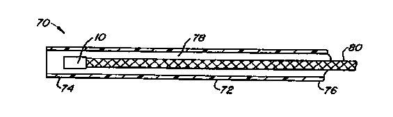
Fig. 6 depicts a catheter system 70, which
incorporates annular array 10 and comprises a catheter body 72
having a distal end 74 and a proximal end 76. The catheter
system 70 further includes a working lumen 78 in which a cable
80 is received. Annular array 10 is operably attached to a
distal end of cable 80. In this manner, rotation of cable 80,
CA 02319615 2000-08-02
WO 99/39641 PCT/IB99/00377
12
and hence rotation of the annular array 10, can occur with
-- respect to a generally stationary catheter body 72. The
annular array 10 may alternatively be configured with a
variety of shapes. As previously described, the annular array
may comprise a plurality of generally circular, concentric
transducer elements. Alternatively, a plurality of generally
elliptical, concentric transducer elements may be used.
Exemplary catheter bodies which may be used with the
annular array of transducer elements 10 include those
disclosed in U.S. Patent No. 4,794,931, U.S. Patent No.
5,203,338, and U.S. Patent No. 5,620,417, the disclosures of
which are hereby incorporated by reference. Cables and
transmission lines which may be used with the present
invention include those disclosed in copending U.S. Patent
Application serial No. (attorney reference
12553-006400), filed contemporaneously herewith, and in U.S.
Patent No. 5,503,155 and U.S. Patent No. 5,108,411, the
disclosures of which are hereby incorporated by reference.
Figs. 7A and 7B depict two alternative arrangements
of an annular array operably attached to the distal end of
cable 80. Fig. 7A depicts an annular array of transducer
elements 100 capable of transmitting ultrasonic waves into a
patient's surrounding tissue as cable 80 is rotated. The
annular array face 102 faces out into the surrounding tissue
of the patient's anatomy. Fig. 7B likewise is configured to
emit ultrasonic waves into the surrounding tissue. However,
Fig. 7B has an annular array of transducer elements 110 that
is axially aligned with cable 80. Such a configuration
requires the reflection of ultrasonic sound waves by a mirror
112 angled at approximately 45 degrees, in order to project
ultrasonic sound waves into the surrounding tissue. Likewise,
reflected signals from the tissue reflect off of mirror 112
and are received by the annular array of transducer elements
110.
Fig. 8 depicts the annular array 20 as previously
discussed in conjunction with Fig. 4, connected to a
filter/controller 120. Because this embodiment uses a single
transmission line 60 to transmit electrical signals to and
CA 02319615 2000-08-02
WO 99/39641 PCT/IB99/00377
13
from a plurality of transducer elements 22, 24, 26, 28, a
system for controlling and processing the electrical signals
is provided. The filter/controller 120 is used to control
signals sent to and received from the transducer elements 22,
24, 26, 28 as described in greater detail hereinafter.
A method of using a single transmission line 60 for
transmitting multiple transducer element signals will now be
described. The frequency at which the transducer elements 22,
24, 26, 28 emit ultrasonic waves is a function of a resonant
frequency of each transducer element 22, 24, 26, 28 and the
frequency of the excitation pulse sent to the transducer
elements 22, 24, 26, 28. By configuring different transducer
elements 22, 24, 26, 28 in the annular array 20 to resonate at
different frequencies, and then using a broad banded
excitation pulse emitted over the full frequency range of all
transducer elements 22, 24, 26, 28 in the array, the return
signals received from those transducer elements will vary in
frequency. Fig. 9 depicts a frequency and amplitude plot of
an excitation pulse used to excite transducer elements 22, 24,
26, 28. The broadbanded nature of such a pulse results in the
excitation of each transducer element 22, 24, 26, 28.
By configuring transducer elements 22, 24, 26, 28 to
each operate at a different resonant frequency, electrical
signals returning from the transducers 22, 24, 26, 28 comprise
distinct frequency characteristics depending on the particular
transducer element the signal is returning from. As a result,
a single transmission line 60 can be used to carry a plurality
of signals from transducer elements 22, 24, 26, 28 to the
filter/controller 120. The filter/controller 120 uses a
plurality of frequency filters, such as high pass, low pass
and band pass filters, to filter out undesired frequency
ranges and separate the signals.
For example, a single transmission line can transmit
four signals to the filter/controller 120 which sends the
signals to four different filters. Each filter can be "tuned"
to the frequency of a particular transducer element, such that
each filter allows only a portion of the frequency range
corresponding to one transducer element to pass through. By
CA 02319615 2000-08-02
WO 99/39641 PCT/IB99/00377
14
using frequency filters in the desired frequency ranges, the
filter/controller 120 can separate out the returning signals.
Fig. 10 depicts four filtered signals received from four
different transducers 22, 24, 26, 28. The filter/controller
120 then uses one or more signals to produce an image of a
body lumen.
For imaging close to the face 36 of annular array
20, it may be desirable to use only transducer elements near
the center of annular array 20. By exciting only the
centermost transducer elements, an aperture of the annular
array 20 is reduced. For example, in annular array 20
depicted in Fig. 5, only transducer element 22 would be
excited. In this manner, only the centermost transducer
element 22 is used to produce an image close to the array face
36. Similarly, transducer elements 22, 24 could be excited.
In this manner, the two centermost transducer elements 22, 24
of annular array 20 would be used, thereby reducing the
aperture of annular array 20.
The invention has now been described in detail.
However, it will be appreciated that certain changes and
modifications may be made. Therefore, the scope and content
of this invention are not limited by the foregoing
description. Rather, the scope and content are to be defined
by the following claims.