Language selection

Search

Patent 2320069 Summary

Third-party information liability

Some of the information on this Web page has been provided by external sources. The Government of Canada is not responsible for the accuracy, reliability or currency of the information supplied by external sources. Users wishing to rely upon this information should consult directly with the source of the information. Content provided by external sources is not subject to official languages, privacy and accessibility requirements.

Claims and Abstract availability

Any discrepancies in the text and image of the Claims and Abstract are due to differing posting times. Text of the Claims and Abstract are posted:

  • At the time the application is open to public inspection;
  • At the time of issue of the patent (grant).
(12) Patent Application: (11) CA 2320069
(54) English Title: DEVICE FOR A CONTAINER WITH A HANDLE
(54) French Title: DISPOSITIF DESTINE A UN CONTENEUR DOTE D'UNE POIGNEE
Status: Deemed Abandoned and Beyond the Period of Reinstatement - Pending Response to Notice of Disregarded Communication
Bibliographic Data
(51) International Patent Classification (IPC):
  • B65D 25/28 (2006.01)
  • B65D 01/28 (2006.01)
  • B65D 25/22 (2006.01)
(72) Inventors :
  • LINDBERG, LINA (Sweden)
(73) Owners :
  • LINA LINDBERG
(71) Applicants :
  • LINA LINDBERG (Sweden)
(74) Agent: ADE & COMPANY
(74) Associate agent:
(45) Issued:
(86) PCT Filing Date: 1999-02-12
(87) Open to Public Inspection: 1999-09-02
Availability of licence: N/A
Dedicated to the Public: N/A
(25) Language of filing: English

Patent Cooperation Treaty (PCT): Yes
(86) PCT Filing Number: PCT/SE1999/000188
(87) International Publication Number: SE1999000188
(85) National Entry: 2000-08-14

(30) Application Priority Data:
Application No. Country/Territory Date
9800406-2 (Sweden) 1998-02-12

Abstracts

English Abstract


The invention is related to a device in a container of the type basket for
merchandise or customer's basket for providing a handle or grip, which is
properly designed from an ergonomic point of view. The handle or grip design,
which is common today, requires the lifting hand to have to be rotated into an
unnatural angle. If the lifting hand would assume the natural angle at rest, a
long side of the basket will be turned forwardly in the walking direction. The
invention solves this by orientating the grip or handle (2) with its
longitudinal direction substantially parallel to a long side of the basket
whereas at the same time the attachment (3, 4) of the handle to the basket
along one long side provides for a maximum amount of availability for handling
merchandise present in the basket.


French Abstract

L'invention concerne un dispositif destiné à un conteneur de type panier de marchandises ou panier de client, et conçu pour procurer une poignée ou une anse de conception ergonomique. Actuellement, la poignée ou l'anse exigent que la main qui porte le panier doit être tournée dans un angle non naturel. Pour que la main qui porte le panier, ait un angle naturel au repos, il faut mettre un grand côté du panier de face dans le sens de la marche. Pour résoudre ce problème, la poignée ou l'anse (2) est orientée de telle façon que sa direction longitudinale soit sensiblement parallèle au grand côté du panier. De plus, la fixation (3, 4) qui relie l'anse au panier et qui est placée sur toute la longueur d'un grand côté du panier, offre une accessibilité maximale pour la manipulation des marchandises contenues dans le panier.

Claims

Note: Claims are shown in the official language in which they were submitted.

6
Claims:
1. A device in a container (1) having a handle (2), which is
connected to the container by means of a hinge (11) and which
extends substantially parallel to a pivot axis (12) formed by
the hinge (11 ) at a distance from said pivot axis, characterized
in that the pivot axis (12) is sidewardly displaced from a
centre of the container towards a side of the container.
2. A device according to claim 1, characterized in that the
hinge (11) is arranged at a side of the container.
3. A device according to any of claims 1-2, characterized in
that the container (1) has an elongated shape and that the
handle extends in the longitudinal direction of the container.
4. A device according to claim 3, characterized in that the
hinge (11) is arranged at a long side of the container.
5. A device according to any of claims 3 and 4, characterized
in that the extent of the handle in the longitudinal direction
thereof is smaller than the extent of the container along the
handle (2).
6. A device according to any preceding claim, characterized in
that the handle (2) is connected to a first part (4) comprised
in the hinge via an arm (3).
7. A device according to claim 6, characterized in that the first
part (4), which extends substantially parallel to the handle
(2), forms the hinge (11) between the container (1) and the
handle (2) together with a second part (7), which is formed in
or connected to a rim (5) on one side of the container (1).
8. A device according to any preceding claim, characterized by
means for making the handle restrictedly pivotably movable

7
between a downwardly pivoted position (2a) and a maximally
upwardly pivoted position (2b), which substantially corresponds
to such positioning of the handle that it intersects or
is located close to a vertical line through the centre of the
bottom of the container.
9. A device according to claim 8, characterized in said
restricting means being formed by the first and second parts
(4, 7).
10. A device according to claim 8, characterized by said
restricting means comprising a band or a string or similar
anchored in the arm (3) and in the container (1).
11. A device according to any of claims 1-4 and 6-10, characterized
in that the handle (2') has substantially the same
extent as the container (1') and is connected to the container
via an arm (3') in each end of the handle.
12. A device according to any preceding claim, characterized in
that the handle (2), including an arm or arms (3), together
with the container (1) has such a design that a plurality of
identical units handle/container are stackable.
13. A device according to any preceding claim, characterized in
that the container is a stackable carrier for merchandise, in
particular a basket for merchandise.

Description

Note: Descriptions are shown in the official language in which they were submitted.


CA 02320069 2000-08-14
WO 99143564 PCTISE99/00188
DEVICE FOR A CONTAINER WITH A HANDLE
The invention is related to a device according to the precharac-
terising part of claim 1. Although the invention generally speak-
ing is applicable to a wide variety of different types of containers
for providing ergonomically advantageous lifts and dis-
placements thereof via the handle of the container, it is particu-
larly preferred to apply the invention to such containers which
have the character of carriers for merchandise, in particular in
the form of baskets for merchandise. These are intended to be
stackable in each other to reduce the space requirement. Such
containers or carriers for merchandise have as a rule an elon-
gated shape in horizontal sections.
It is well known that an ergonomic design of handles or grips is
most important to provide convenient and comfortable lifts also
of relatively modest weights. This is particularly important when
the weight in question also should be displaced. An example of
such a situation is picking and displacement of everyday com
modities in a basket for merchandise or customer's basket.
The baskets presently available are provided with a handle in
the form of a bail arranged transversely to the longitudinal direc-
tion of the basket. The upper horizontal part of this bail func-
tions as a handle. This formation of the grip means that the lift-
ing hand must be rotated, from a position generally parallel to
the walking direction in a relaxed situation, to a direction where
the back of the hand either will be rotated to be turned forwardly
in the walking direction {pronated position) or conversely with
the back of the hand turned backwards (supinated position).

CA 02320069 2000-08-14
WO 99/43564 2 PCT/SE99/00188
This involves a load in the form of a tension build up in the mus-
cles and ligaments of the arm as well as the shoulder portion. If
then the load caused by the weight of the basket with its content
discussed in the example is added, it is easily understandable
that the handling becomes inconvenient as well as laborious.
The object of the invention is to reduce this problem by provid-
ing a container having a handle designed to increase the ergo-
nomic comfort.
The solution to the problem appears from the enclosed claims,
and then in particular claim 1.
The invention will be explained more closely hereinafter with
reference to the drawings.
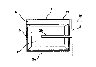
Fig 1 illustrates diagrammatically in a sideview a basket for
merchandise having a carrying handle according to a
first embodiment of the invention.
Fig 2 is a view along the line ll-II in fig 1.
Fig 3 is a view along the line III-III in fig 1.
Fig 4 is a section along the line IV-IV in fig 1.
Fig 5 is a view similar to the one in fig 2 but illustrating a
different embodiment for restricting the freedom of piv-
oting of the handle.
Fig 6 illustrates diagrammatically in a sideview a basket for
merchandise having a carrying handle according to a
second embodiment of the invention.
Fig 7 is a view along the line VII-VII in fig 6.

CA 02320069 2000-08-14
WO 99143564 3 PCT/SE99/00188
Fig 8 illustrates diagrammatically baskets for merchandise in
a stacked state; said baskets having handles according
to any of the embodiments of the invention.
Fig 9 illustrates a further embodiment of the invention from
above.
Fig 10 illustrates a section along the line X-X in fig 9.
The drawings illustrate diagrammatically a design and connec-
tion of a handle to a basket for merchandise or a customer's
basket. The invention is not only restricted to this purpose but is
intended to be generally applicable also to other types of
containers movable by handpower. The device comprises a
handle 2 connected to at least one arm 3, which in turn is
connected to the container via a hinge 11 forming a pivot axis
12 for the handle 2. This pivot axis 12 is substantially parallel to
the handle 2. The hinge proper is in fig 1-4 formed by a first part
4 and a second part 7, which engage hingedly with each other.
The part 4 connected to the arm 3 forms together with the part
7, which is provided on the container 1 and formed by or
connected to the rim 5, said hinge 11. This hinge provides for
movability of the unit formed by the handle 2, the arm or arms 3
and the part 4 in relation to the container 1. The motion in the
hinge thus formed occurs around the pivot axis 12 comprised in
the part 4. The movement is restricted so that the handle may
assume two extreme positions, on one hand a downwardly
pivoted position, wherein the handle 2 and arm/arms 3 will
assume an almost horizontal position, and on the other hand a
raised position in connection with a lift. In this latter position the
handle 2 is present, as seen in the plane of rotation of the
hinge, in a point substantially within a conceived vertical line
through the centre of the basket.
A first embodiment is illustrated in fig 1, where the handle 2 is
designed with a connection to the container 1 consisting of an

CA 02320069 2000-08-14
WO 99/43564 4 PCTISE99/00188
arm 3 and a part 4. The handle is in this embodiment shorter
than the total length of the basket.
Fig 2 illustrates the same embodiment viewed from a short side
of the basket. The two extreme positions the handle 2 with the
arm 3 may assume appear from fig 2. In this projection the han-
dle will, in its raised position 2b, be present in a conceived ver-
tical plan Lp through the centre of the basket.
Fig 3 illustrates again the first embodiment, this time viewed
from above according to the line III-III in fig 1. The downwardly
pivoted position 2a of the handle and the upwardly pivoted
position 2b thereof appear in the figure.
Fig 4 illustrates an example on how it is possible to restrict the
range of movement within the hinge, which is comprised of the
part 4 and the part 7 formed by the rim 5 or connected to the
rim. The stationary part 7, which belongs to the basket, of the
hinge 11 has a bulb 8 protruding into the space for the part 4.
This bulb interferes with the possibility of movement of the part
4 in a rotating direction and restricts, accordingly, the range of
movement of the arm 3 and the handle 2 in the intended
manner.
25- Fig 5 illustrates another way of restricting pivoting of the handle
2. Holes 9 are provided in the arm 3 and in the rim 5. Between
these holes there is a connection in the form of a band 10 or
string to delimit movement of the handle in the upper position
thereof.
Fig 6 illustrates another embodiment of the handle 2'. The han-
dle is here extended and comprises basically the same length as
the container 1'. Besides, the handle is provided with an arm 3'
connected in each end to the part 4'. The mechanism for re-
stricting the movement in the plane of rotation is the same as
illustrated in fig 4 or 5.

CA 02320069 2000-08-14
WO 99/43564 5 PCT/SE99/00188
Fig 7 illustrates the same embodiment of the handle as in fig 6
seen from above according tv the line VII-VII in fig 6.
Fig 8 illustrates a stack of identical baskets.
Fig 9 illustrates a modified embodiment, where the basket has a
narrowed waist, in the area of which the hinge 11" is provided.
The parts 4" and 7" forming the hinge 11" are here substantially
shorter than the longitudinally extent of the basket. For the rest
the arm 3~ has here a more complex shape adapted to the ex-
ternal contour of the basket. The position of the handle 2" for
carrying appears with dashed lines.

Representative Drawing
A single figure which represents the drawing illustrating the invention.
Administrative Status

2024-08-01:As part of the Next Generation Patents (NGP) transition, the Canadian Patents Database (CPD) now contains a more detailed Event History, which replicates the Event Log of our new back-office solution.

Please note that "Inactive:" events refers to events no longer in use in our new back-office solution.

For a clearer understanding of the status of the application/patent presented on this page, the site Disclaimer , as well as the definitions for Patent , Event History , Maintenance Fee  and Payment History  should be consulted.

Event History

Description Date
Application Not Reinstated by Deadline 2003-02-12
Time Limit for Reversal Expired 2003-02-12
Deemed Abandoned - Failure to Respond to Maintenance Fee Notice 2002-02-12
Inactive: Cover page published 2000-11-14
Inactive: First IPC assigned 2000-11-08
Inactive: Notice - National entry - No RFE 2000-10-24
Application Received - PCT 2000-10-20
Application Published (Open to Public Inspection) 1999-09-02

Abandonment History

Abandonment Date Reason Reinstatement Date
2002-02-12

Maintenance Fee

The last payment was received on 2001-01-22

Note : If the full payment has not been received on or before the date indicated, a further fee may be required which may be one of the following

  • the reinstatement fee;
  • the late payment fee; or
  • additional fee to reverse deemed expiry.

Patent fees are adjusted on the 1st of January every year. The amounts above are the current amounts if received by December 31 of the current year.
Please refer to the CIPO Patent Fees web page to see all current fee amounts.

Fee History

Fee Type Anniversary Year Due Date Paid Date
Basic national fee - small 2000-08-14
MF (application, 2nd anniv.) - small 02 2001-02-12 2001-01-22
Owners on Record

Note: Records showing the ownership history in alphabetical order.

Current Owners on Record
LINA LINDBERG
Past Owners on Record
None
Past Owners that do not appear in the "Owners on Record" listing will appear in other documentation within the application.
Documents

To view selected files, please enter reCAPTCHA code :


To view images, click a link in the Document Description column. To download the documents, select one or more checkboxes in the first column and then click the "Download Selected in PDF format (Zip Archive)" or the "Download Selected as Single PDF" button.

List of published and non-published patent-specific documents on the CPD .

If you have any difficulty accessing content, you can call the Client Service Centre at 1-866-997-1936 or send them an e-mail at CIPO Client Service Centre.


Document
Description 
Date
(yyyy-mm-dd) 
Number of pages   Size of Image (KB) 
Representative drawing 2000-11-13 1 5
Description 2000-08-13 5 201
Abstract 2000-08-13 1 57
Claims 2000-08-13 2 78
Drawings 2000-08-13 9 96
Reminder of maintenance fee due 2000-10-22 1 110
Notice of National Entry 2000-10-23 1 193
Courtesy - Abandonment Letter (Maintenance Fee) 2002-03-11 1 182
PCT 2000-08-13 8 298