Note: Descriptions are shown in the official language in which they were submitted.
CA 02320210 2000-07-28
PCA98ZO4R
-1-
FUEL CELL WITH A PROTON CONDUCTING ELECTROLYTE
The invention relates to a fuel cell with a proton conducting electrolyte, an
anode,
and a cathode.
In fuel cells, the chemical energy stored in the fuel is directly converted
into electri-
cal energy and heat. As fuel there are used for example pure hydrogen,
methanol,
or natural gas, and the fuel reacts in the in fuel cell with the oxidant,
which in most
cases is pure oxygen or the oxygen contained in the air. In this reaction,
aside from
electrical energy and heat there is also produced water, and when using
carbonic
fuels, in addition carbon dioxide. Fuel and oxidant together are referred to
as oper-
ating material.
The single fuel cell comprises an anode and a cathode, between which the
electro-
lyte is disposed. The fuel is continuously fed to the fuel cell's anode gas
space lay-
ing before the anode, the oxidant is continuously fed to the fuel cell's
cathode gas
space laying before the cathode, the reaction products are continuously
carried
away. The different types of fuel cells are commonly classified using the
employed
electrolyte. Electrolytes being conductive for protons are used in fuel cells,
in which
protons are separated at the anode from the fuel while releasing electrons.
The pro-
tons migrate through the proton conducting electrolyte to the cathode, where
they
react with the oxygen to form water while incorporating electrons.
One example for such fuel cells is the so-called polymer membrane fuel cell
which
employs as electrolyte a membrane made of perfluorinated plastic material. At
pre-
sent, semipermeable membranes on the basis of poiy(perfluoroaikene) sulfonic
acid, as for example Nafion R 117 of Du Pont are mainly used. For the
production
of the fuel ceii, one face of the electrolyte membrane is coated with the
anode mate-
rial which usually is platinum or a platinum-ruthenium alloy, and the opposite
face is
coated with the cathode material which preferably is platinum.
CA 02320210 2007-08-30
2
The polymer membrane fuel cell can be operated with hydrogen or methanol. When
using methanol, it is also referred to as direct methanol fuel cell. The
electrode reac-
tions of the polymer membrane fuel cell operated with hydrogen read as
follows:
anode: H2 -a 2 H+ + 2 e-
cathode: 02 + 4 H+ + 4 e- -+ 2 H20
The electrode reactions of the direct methanol fuel cell read as follows:
anode: CH3OH + H20 -+ CO2 + 6 H+ + 6 e-
cathode: 02 + 4 H+ + 4 e- -+ 2 H20
One disadvantage of these known polymer membrane fuel cells is that the
electro-
lyte membrane allows both the protons and, though in a smaller extent, the
fuel,
that is the molecular hydrogen (H2) or the methanol molecules (CH3OH), to pass
through. This results in a loss in fuel cell efficiency. In case of the direct
methanol
fuel cell this unwelcome effect is made worse because the water (H20) existing
on
the anode side as well as on the cathode side, as well penetrates into the
Nafion foil
so that said foil swells up and allows even more methanol to pass through.
It is the object of the invention to prevent in a fuel cell of the type
mentioned at the
beginning, the migration of the fuel through the proton conducting electrolyte
from
the anode side to the cathode side.
This object is achieved in such a way that the fuel cell comprises at least
one hy-
drogen permeable barrier layer composite comprising two outer layers and a
core
layer arranged there between, each outer layer being essentially made of
palladium
and/or an alloy on the basis of palladium, and the core layer being
essentially made
of niobium and/or tantalum and/or an alloy on the basis of one of these
metals.
Preferably, the layer composite according to the invention is essentially made
of the
metals palladium, niobium, and tantalum, which exhibit a high diffusibility to
atomic
hydrogen but on the other hand are impermeable to larger atoms and molecules,
in
= CA 02320210 2007-08-30
3
particular molecular hydrogen, water and methanol. The barrier layer composite
serves to separate the anode gas space from the cathode gas space in such a
way
that the fuel cannot migrate through the electrolyte from the anode side to
the cath-
ode side. The incorporation of the hydrogen in the metal lattice occurs while
forming
metal hydride.
Preferably, the three-layer design is based on the follawing considerations:
tantalum exhibits a
high diffusibility to hydrogen atoms which is higher than that of palladium.
On the
other hand, the energy required for the transition of the hydrogen from the
gas
phase into the hydride phase is lower in the case of palladium than in the
case of
tantalum. However, palladium is more expensive than tantalum. These
correlations
are as well valid for niobium which is chemically allied with tantalum. The
barrier
layer composite according to the invention is cheaper than a diffusion layer
essen-
tially made of palladium, because the outer layers can be made very thin, and
it in-
corporates the hydrogen easier than a diffusion layer essentially made of
tantalum
and/or niobium. The two outer layers essentially made of palladium provide, be-
cause of the low transition energy, for an easy incorporation of the hydrogen
from
the gas phase into the outer layer, and the subsequent transition from the
outer
layer into the core layer requires only a much lower energy than the
transition from
the gas phase into tantalum or niobium. Since the material of the core layer
is rela-
tively cheap, the latter can be made almost as thick as desired and thus
provide for
the stability of the barrier layer composite.
There are several possibilities for the arrangement of each barrier layer
composite
relative to the electrolyte.
A first variant is that the electrolyte comprises two plies between which is
arranged
a barrier layer composite. This arrangement has the advantage that the
electrolyte
which contains in its interior the barrier layer composite, can be coated with
the
electrode materials exactly like a usual electrolyte without barrier layer
composite.
CA 02320210 2000-07-28
PCA98ZO4R
-4-
According to a second variant, a barrier layer composite is arranged between
one of
the electrodes and the electrolyte.
According to a third variant, at least one of the electrodes is formed as a
barrier
layer composite. For example, the anode may be substituted by a barrier layer
composite according to the Invention which performs the anode's function so
that, in
contrast to the first and second variant, it is possible to dispense with a
separate
anode layer, that is an anode layer provided in addition to the barrier layer
compos-
ite.
The barrier layer composite may comprise aside from the mentioned three layers
further layers as well which are arranged on the anode side and/or the cathode
side
between the respective outer layer and the core layer. The material of these
addi-
tional intermediate layers may be chosen for example in view of facilitating
the tran-
sition of the hydrogen from the anode sided outer layer into the core layer or
from
the core layer into the cathode sided outer layer.
1s In a first alternative, the intermediate layer is essentially made of an
alloy which es-
sentially contains the main component of the adjoining outer layer and the
main
component of the core layer. Therefore, if the two outer layers are made of a
palla-
dium alloy and the core layer is made of a niobium alloy then, for example, an
in-
termediate layer which is essentially made of a palladium-niobium alloy may be
ar-
ranged between each outer layer and the core layer.
In a second alternative, the intermediate layer is essentially made of a
mixture
which essentially contains the material of the adjoining outer layer and the
material
of the core layer. Therefore, the intermediate layer may not only be available
as an
alloy but as well in a different form which depends on the employed
manufacturing
process. The intermediate layer may be deposited on the core layer for example
by
sputtering, the sputtering being carried out by using in a first step the
material of the
core layer and in a second step the material of the outer layer.
A third alternative refers to the case where the core layer is essentially
made of tan-
talum and/or an alloy on the basis of tantalum, and according to this
afternative, the
CA 02320210 2000-07-28
PCA98Z04R
-5-
intermediate layer is essentially made of niobium and/or vanadium and/or an
alloy
on the basis of one of these metals and/or an paiiadium-tantaium alloy.
Therefore,
the intermediate layer may contain metals which are not contained in the core
layer
and the outer layer.
It is preferred that the outer layers are essentially made of a palladium-
silver alloy,
preferably with a content of silver of at least 25% by weight. For a palladium
foil
blows up considerably when incorporating hydrogen, and becomes brittie and
cracky. The dimensional stability Is Improved by the addition of silver.
The core layer preferably is a foil. The other layers may be deposited on the
core
layer one after the other by coating. The coating may be carried out by
sputtering,
powder coating, vacuum evaporation, and the like. The other layers may as well
be
foils. In this case, the deposition of these foil layers may be carried out by
iaminat-
ing.
Since the core layer is made of a material which in comparison with the outer
layers
does have a higher transition energy but also a better diffusibility to
hydrogen to
make up, it may be thicker than each of the other layers and thus provide for
the
desired stability of the barrier layer composite, of the electrolyte membrane,
or even
of the whole fuel cell.
In the following, preferred embodiments of the invention will be described
more pre-
cisely by way of example with reference to the enclosed drawing.
FIG. I is a schematic cross-sectional view of a polymer membrane fuel cell
in a first embodiment;
FIG. 2 is a schematic cross-sectional view of a polymer membrane fuel cell
in a second embodiment;
FIG. 3 is a schematic cross-sectional view of a polymer membrane fuel cell
in a third embodiment; and
CA 02320210 2000-07-28
PCA98ZO4R
-6-
FIG. 4 and 5 show in an enlarged detail view modifications of the barrier
layer
composite of the fuel cells shown in the FIG. 1 to 3.
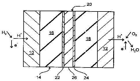
The FIG. I shows schematically the design of a polymer membrane fuel cell in a
first embodiment. The fuel cell comprises an anode 10 and a cathode 12 as well
as
s an electrolyte 14 placed there between. On the left side of the anode 10
there is the
so-called anode gas space, and on the right side of the cathode 12 there is
the
cathode gas space. The electrolyte 14 is a proton conducting membrane in the
form
of a foil made of Nafion R 117 which is coated on its left side in the FIG. 1
with the
anode 10 and on its right side with the cathode 12. For the electrodes 10, 12
there
are used catalytic materials which are chosen in view of the reactions
occurring at
the electrodes 10, 12, such as for example the separation of protons at the
anode
10 and the recombination and reaction of the protons to form water at the
cathode
12. Possible materials are above all noble metals, and preferably platinum and
gold
are used, and for the anode 10 platinum-ruthenium alloys as well. The
electrode
material is usually deposited wet-chemically on the electrolyte membrane 14,
or is
hot pressed as a powder therewith. The electrolyte 14 is approximately 200 pm
thick, each of the electrodes 10, 12 is approximately 100 Nm thick.
According to the first embodiment of the fuel cell as shown in the FIG. 1, the
elec-
trolyte 14 is divided in two plies 16, 18 of equal size between which a
barrier layer
composite 20 is positioned. Therefore, the barrier layer composite 20
separates the
anode gas space from the cathode gas space. The composite 20 consists of two
outer layers 22, 24 and a core layer 26 positioned there between. Each outer
layer
22, 24 is made of palladium and is approximately 0,5 pm thick whereas the core
layer 26 is an approximately 50 to 100 pm thick foil made of tantalum. For the
pro-
duction of the composite 20, the outer layers 22, 24 have been deposited on
the
core layer foil 26 by sputtering.
The thickness of the barrier layer composite 20 is chosen in view of the
barrier func-
tion, but for cost reasons - palladium is more expensive than tantalum - the
core
layer 26 in comparison with the outer layers 22, 24 should be as thick as
possible.
The outer layers 22, 24 must be at least so thick that the hydrogen atoms can
enter
CA 02320210 2000-07-28
PCA98ZO4R
7-
the core layer 26 as easily as possible and exit it again on the other side as
easily
as possible.
With reference to the embodiment of a fuel cell as shown in the FIG. 1, the
manner
of function of a polymer membrane fuel cell operated with hydrogen will now be
de-
scribed.
Molecular hydrogen H2 is continuously fed as fuel to the anode gas space. At
the
anode 10, a hydrogen molecule H2 Is catalytically separated in two protons H+
and
two electrons e-. The electrons e- are led through a current collector (not
shown) to
an electrical consumer (not shown too). They reach the cathode 12 from the con-
sumer via a second current collector (not shown).
The protons H+ produced at the anode 10 enter the anode sided electrolyte ply
16
and migrate through the latter up to the anode sided outer layer 22. There
they re-
combine with electrons e- to form hydrogen atoms H which are incorporated in
the
outer layer 22 whiie forming palladium hydride. The electrons e- required for
the re-
1s combination come from the cathode sided outer layer 24, as wiii be
explained in the
following, and have migrated through the core layer 26.
The hydrogen atoms H dissolved in the pailadium of the outer layer 22 diffuse
through the metal iattice up to the interface with the core layer 26 where
they enter
the iatter while forming tantalum hydride. They diffuse through the core layer
26,
further into the cathode sided outer layer 24 while converting into tantalum
hydride,
and exit the fatter into the cathode sided electrolyte ply 18 while separating
into pro-
tons H+ and electrons e-. These electrons e- migrate, as mentioned above,
through
the cathode sided outer layer 24 and the core layer 26 to the anode sided
outer
layer 22. Through the cathode sided electrolyte ply 18, the protons H+ reach
the
cathode 12 where they combine with the electrons e- fed via the external
consumer
circuit, and with the oxygen 02 continuously fed to the cathode gas space, to
form
water H20. The reaction product water H20 is continuously carried away from
the
cathode gas space.
CA 02320210 2000-07-28
PCA98ZO4R
-8-
Therefore, the barrier layer composite 20 allows only atomic hydrogen H to
pass
through whereas it serves as a barrier for the molecular hydrogen H2.
Aside from the arrangement of the barrier layer composite 20 in the interior
of the
electrolyte 14 as shown in the FIG. 1, other arrangements are possible as
well, ac-
cording to which the barrier layer composite 20 is arranged at the anode sided
or at
the cathode sided surface of the electrolyte 14, as will be described more
precisely
in the following with reference to the FiG. 2 and 3.
In the FIG. 2, there is shown a polymer membrane fuel cell in a corresponding
sec-
ond embodiment, according to which the barrier layer composite 20 is placed at
the
anode side of an one-ply electrolyte 14. This arrangement is in particular
appropri-
ate for the direct methanol fuel cell because it avoids that the water H20
which is
fed to the anode gas space penetrates into the electrolyte 14 and the latter
swells
up. As can be seen, the anode sided outer layer 22 borders on the anode 10
first,
and the electrolyte 14 borders only on the cathode sided outer layer 24.
is With reference of the embodiment of a fuel cell as shown in the FIG. 2, the
manner
of function of a direct methanol fuel cell will now be described.
Methanol CH3OH and water H20 are continuously fed to the anode gas space, and
at the anode, they react to form carbon dioxide C02, protons H+, and electrons
e-.
The electrons e- are led through a consumer circuit (not shown) to the cathode
12,
as was already explained in connection with the FIG. 1. The protons H''
recombine
with electrons e- coming from the cathode sided outer layer 24 and enter the
anode
sided outer layer 22 while forming metal hydride, they diffuse through the
barrier
layer composite 20 as described before, and, from the cathode sided outer
layer 24,
they reach as protons H+ the electrolyte 14 while separating electrons e-. The
pro-
tons H+ migrate through the electrolyte 14 to the cathode 12 where they react
with
the electrons e- from the consumer circuit and with the oxygen 02 continuously
fed
to the cathode gas space, to form water H20 which is continuously carried
away.
CA 02320210 2000-07-28
PCA98Z04R
-9-
Therefore, the barrier layer composite 20 allows only atomic hydrogen H to
pass
through whereas it serves as a barrier between the two gas spaces for larger
mole-
cules, that is in particular methanol CH3OH and water H20.
The fuel cell shown in the FIG. 2 may be manufactured in the following way.
First,
the two outer layers 22, 24 are deposited on the core layer 26, for example by
sput-
tering. Then, the anode 10 is deposited on the anode sided outer layer 22,
which
may be carried out by sputtering as well. On the cathode sided outer layer 24,
the
electrolyte 14 is deposited. The face of the electrolyte 14 opposite to the
outer layer
24 is coated with the cathode 12, for example by sputtering or chemical wet-
deposition.
The FIG. 3 shows a polymer membrane fuel cell in a third embodiment which
repre-
sents a modification of the fuel cell shown in the FIG. 2. According to this
modifica-
tion, the anode layer 10 of the fuel celi of the FIG. 2 is missing and instead
the an-
ode sided outer layer 22 of the FIG. 2 serves as anode; so to speak, the outer
layer
is 22 of the FIG. 2 and the anode 10 of the FIG. 2 are combined in a
combination
layer 28. This combination layer 28 is essentially made of a mixture which
contains
as a first component the material of the anode 10 of the FIG. 2, that is for
example
platinum, and as second component the material of the outer layer 22 of the
FIG. 2,
that is for example palladium. This mixture may be an alloy of these metals
but
other types of mixture are possible as well. The combination layer 28 may be
de-
posited on the core layer 26 by sputtering using a platinum-palladium alloy as
target
material.
However, the unchanged outer layer 22, that is the outer layer 22 without
addition of
platinum, may also be used as anode because the anode reactions even occur
with
palladium as catalyst.
The modification described above in connection with the FIG. 3 may be
transferred
analogously to the cathode side. In this case the cathode sided outer layer 24
of the
FIG. 2 serves, on Its own or as combination layer, as cathode.
CA 02320210 2000-07-28
PCA98ZO4R
-10-
It is emphasized that the two outer layers 22, 24 may as well be made of
different
materials. For example, the content of palladium may be different, or the one
outer
layer may be made of palladium and the other may be made of a palladium-silver
alloy. The core layer 26 too must not necessarily contain tantalum as main
compo-
nent. Possible main components are as well niobium or a mixture of tantalum
and
niobium, as well as niobium alloys, tantalum alloys, and niobium-tantalum
alloys.
The core layer 26 may as well comprise additions of substances contained in
the
outer layers 22, 24. In addition, at least one further intermediate layer may
be posi-
tioned between each outer layer 22, 24 and the core layer 26.
In the FIG. 4 there is shown a modification of the barrier layer composite 20
used in
the fuel cells shown in the FIG. 1, 2 and 3. Between the core layer 26 and the
an-
ode sided outer layer 22, there Is arranged an intermediate layer 30. The
intermedi-
ate layer 30 may be essentially made of an alloy which contains essentially
the main
component of the adjoining, anode sided outer layer 22 and the main component
of
the core layer 26, but it may as well be essentially made of a mixture which
contains
essentially the material of the adjoining, anode sided outer layer 22 and the
material
of the core layer 26. Therefore, if for example the core layer 26 is made of a
tanta-
lum alloy and the anode sided outer layer 22 is made of a palladium-silver
alloy then
the material for the intermediate layer 30 may be a palladium-tantalum alloy,
but for
example as well a mixture, preferably an alloy, of the palladium-silver alloy
and the
tantalum alloy.
However, other materials for the intermediate layer 30 are possible as well,
as far
as they offer a sufficient diffusibility to the hydrogen atoms. For example,
in case of
the core layer 26 and the outer layer 22 of the previous example, the
intermediate
layer 30 may as well be essentially made of niobium or a niobium alloy or
vanadium
or a vanadium alloy or a mixture, preferably an alloy, of two or more of these
sub-
stances. In a similar manner, intermediate layers 32 may be arranged between
the
cathode sided outer layer 24 and the core layer 26 as well, as is shown in the
FIG. 5.