Language selection

Search

Patent 2320397 Summary

Third-party information liability

Some of the information on this Web page has been provided by external sources. The Government of Canada is not responsible for the accuracy, reliability or currency of the information supplied by external sources. Users wishing to rely upon this information should consult directly with the source of the information. Content provided by external sources is not subject to official languages, privacy and accessibility requirements.

Claims and Abstract availability

Any discrepancies in the text and image of the Claims and Abstract are due to differing posting times. Text of the Claims and Abstract are posted:

  • At the time the application is open to public inspection;
  • At the time of issue of the patent (grant).
(12) Patent Application: (11) CA 2320397
(54) English Title: HOSE COUPLING AND METHOD OF MANUFACTURE
(54) French Title: RACCORD DE TUYAU SOUPLE ET METHODE DE FABRICATION
Status: Dead
Bibliographic Data
(51) International Patent Classification (IPC):
  • F16L 33/20 (2006.01)
  • F16L 11/10 (2006.01)
  • F16L 35/00 (2006.01)
(72) Inventors :
  • ASSENHEIMER, KEVIN C. (United States of America)
(73) Owners :
  • FLUID ROUTING SOLUTIONS, INC. (United States of America)
(71) Applicants :
  • DAYCO PRODUCTS, INC. (United States of America)
(74) Agent: BORDEN LADNER GERVAIS LLP
(74) Associate agent:
(45) Issued:
(22) Filed Date: 2000-09-22
(41) Open to Public Inspection: 2001-03-24
Examination requested: 2005-09-15
Availability of licence: N/A
(25) Language of filing: English

Patent Cooperation Treaty (PCT): No

(30) Application Priority Data:
Application No. Country/Territory Date
09/405,875 United States of America 1999-09-24

Abstracts

English Abstract


A flexible elastomeric fluid conveying hose which includes a rigid coupling
having
a member extending partially into the hose body. A stress relief member, in
the form of
a helical spring, is mounted directly on the coupling member and also inserted
into the
body to prevent kinking or collapsing of the hose.


Claims

Note: Claims are shown in the official language in which they were submitted.


THE EMBODIMENTS OF THE INVENTION IN WHICH AN
EXCLUSIVE PROPERTY OR PRIVILEGE IS CLAIMED ARE
DEFINED AS FOLLOWS:

1. In a flexible fluid conveying hose having an elastomeric body and a
rigid coupling attached to said body and having a generally cylindrical member
inserted into at least one end of said body; the improvement comprising
reinforcing
means mounted directly on the outer surface of said member and
secured thereto, and extending a portion of said reinforcing means into said
body to
provide stress relief at said at least one end to avoid kinking and collapsing
thereof.

2. The hose of claim 1 wherein said reinforcing means is a helical
spring.
3. The hose of claim 2 wherein said spring is made of metal.
4. The hose of claim 2 wherein said spring is made of plastic.
5. The hose of claim 2 wherein said spring has spaced coils of a
constant diameter throughout its length.
6. The hose of claim 5 comprising means for retaining at least one of
said coils on said member.
7. The hose of claim 6 wherein said coil retaining means is in the form
of a groove extending around the outer surface of said member.
8. The hose of claim 6 further comprising a rigid sleeve surrounding
said at least one end of said body and compresses said body around at least
one of
said coils and said member.
9. The hose of claim 6 wherein said at least one of said coils is crimped
around said member.
10. The hose of claim 1 wherein said retaining means has a length which


5


is between 4 and 7 times the length of said member.
11. The hose of claim 1 wherein said hose is a garden hose.
12. The hose of claim 1 wherein said hose is an air hose.
13. In a flexible fluid conveying hose having an elastomeric body, a rigid
coupling adapted to be attached to at least one end of said body and having a
generally cylindrical member adapted to be inserted in said body; the
improvement
comprising reinforcing means mounted on and secured directly to
the outer surface of said member, a portion of said reinforcing means adapted
to
extend into said body to provide stress relief at said at least one end to
avoid kinking
and collapsing thereof.
14. The coupling of claim 13 wherein said reinforcing means is a helical
spring.
15. The coupling of claim 14 wherein said spring has coils of a constant
diameter throughout its length.
16. The coupling of claim 15 wherein said member has means for
retaining at least one of its coils.
17. The coupling of claim 16 wherein said coil retaining means is in the
form of a groove extending around the entire surface thereof.
18. The coupling of claim 16 wherein at least one of said coils is crimped
around said member.
19. The coupling of claim 13 wherein said retaining means has a length
which is between 4 and 7 times the length of said member.
20. In a method of forming a flexible fluid conveying hose having an
elastomeric body and a rigid coupling attached to said body and having a
generally
cylindrical member inserted into at least one end of said body; the
improvement
6


comprising the steps of mounting a reinforcing means directly on the outer
surface of
said member, securing said reinforcing means on said member, and extending a
portion of said reinforcing means into said body to provide stress relief at
said at least
one end to avoid kinking and collapsing thereof.
21. The method of claim 20 comprising the further step of forming said
reinforcing means of a helical spring.
22. The method of claim 21 comprising the further step of forming said
spring with coils of a constant diameter throughout its length.
23. The method of claim 21 comprising the further step of providing
means for retaining at least one of said coils on said member.
24. The method of claim 23 comprising the further step of forming a
groove extending around the outer surface of said member to retain said at
least one
of said coils.
25. The method of claim 23 comprising the further step of crimping said
at least one of said coils around said member.
26. The method of claim 23 wherein said hose includes a rigid sleeve
surrounding said at least one end of said body, comprising the further step of
compressing said outer sleeve around said body and said at least one of said
coils
and said member.
7

Description

Note: Descriptions are shown in the official language in which they were submitted.


CA 02320397 2000-09-22
HOSE COUPLING AND METHOD OF MANUFACTURE
Background of the Invention
Field of the Invention
The present invention relates to a hose coupling for incorporation into a
flexible
elastomeric fluid conveying hose, such as a garden hose or air hose. The
coupling is
designed to reduce stress on the end of the hose and eliminate kinking during
use.
Prior Art Statement.
Various designs have been used for the stress relief on hose ends, including
designs which utilize a spring mounted on a washer that is inserted into the
hose
coupling, as shown in the patent to Hensen, No. 4,487,444. Patent No. 790,971,
issued
to Nicholls, utilizes a spring extending inside a hose and secured to the
inner surfaces
thereof.
Summary of the Invention
According to the present invention, stress relief of the hose coupling is
provided
by a helical spring having a constant diameter throughout its length, the
spring being
mounted on and secured directly to the outer surface of the ferrule which is
an integral
component of the coupling. The spring extends into at least a portion of the
hose body
just beyond the end of the ferrule and thus eliminates the stress and kinking
which
occurs when the end is bent. By securing the spring to the ferrule, the spring
will be
secured during bending so that it will not slip into the hose body. The
construction may
be used on both the male and female ends of a fluid conveying hose, such as a
garden
hose, an air brake hose, or an industrial air hose.
It is a principal object of this invention therefore, to provide a hose
coupling that
will eliminate stress on the end of the hose.
It is a further object to prevent kinking and collapsing of the hose end when
it is


CA 02320397 2000-09-22
bent during use.
It is another object to provide a member that is secured to the ferrule of the
hose
coupling.
It is still another object to utilize a helical spring as the stress relief
member and
secure it to the ferrule in a manner that will prevent it from becoming
detached.
Brief Description of the Drawings
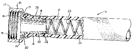
FIG. 1 is a side view in partial section of a hose with the novel
coupling.
FIG. 2 is an exploded view of the coupling and spring reinforcement.
FIG. 3 is a view similar to FIG. 2 of a different coupling and spring
reinforcement.
FIG. 4 is a view similar to FIG. 1 illustrating a modified form of hose.
Description of Preferred Embodiments
Referring to FIG. 1, reference numeral 11 illustrates a flexible hose having a
hose body 12 made of an elastomeric material such as rubber. The hose shown is
a
garden hose which is not reinforced, but other types of fluid conducting
hoses, both
reinforced and non-reinforced are contemplated as being within the scope of
the
present invention. Such hoses may conduct air, such as for air brakes or
industrial
uses. The hose 11 comprises a coupling 13, preferably made of a metal such as
brass
or steel, having a ferrule 14 which is a generally cylindrical member and
consists of a
tubular shaft 15 which terminates in an enlarged outer end 16. A collar 17
with internal
threads 18 is freely rotatable, and acts as a female coupling to engage a
mating male
member, such as a hose faucet. The collar is secured to the ferrule by causing
the
surface 19 to engage the outer end 16 while surface 20 engages a spaced ring
member
21 of the ferrule. The shaft 15 has spaced annular rings 22. The stress relief
member
2


CA 02320397 2000-09-22
is a helical spring 23 having spaced coils 24 which are of a constant diameter
throughout the length of the spring. The coils may have a circular cross-
section as
shown, or may be a so-called "flat spring", meaning that the coils are
rectangular in
cross-section. The spring coils may be made of metal or plastic, as is well
known in the
art. One or more of the end coils are mounted on and retained by the outer
surface of
the shaft 15 of the ferrule by various methods known in the art, such as
crimping. The
coupling assembly is inserted into the hose body 12 so that the shaft 15 and
the spring
23 extend into the hose body and crimped into place by an outer rigid sleeve
25 which
compresses the hose body and compressing the body around the shaft. This
pressure
also causes the spring 23 to be secured around the shaft. As better shown in
FIGS. 2
and 3, the end coils 24 are placed in a groove 26. The spring extends just
beyond the
inner end of the ferrule and is preferably between 4 and 7 times in length
compared to
the length of the ferrule 14, in order to obtain the best results.
FIG. 2 is an exploded view which illustrates a preferred means for retaining
one
or more coils of the spring on the hose coupling, showing in greater detail
the shaft 15
of ferrule 14 with its groove 26 extending into and around the outer surface
of the shaft.
One or more coils 24 of the spring 23 are snapped into this groove for locking
them into
place. This arrangement may be used as the sole retaining means for the coils,
or may
be used to supplement the crimping of the coils referred to above. Any of
these
arrangements are important because they prevent the spring from slipping down
into
the hose body and thus causing the spring to lose its effectiveness in stress
or stain
relief.
FIG. 3 is an exploded view of a hose coupling 41 which is constructed like
coupling 13 except that instead of having a rotatable female collar it has a
fixed male
collar 42 with external threads 43 designed to engage a member similar to
collar 17
3


CA 02320397 2000-09-22
which may be found, for example, on a hose nozzle. The end coils 24 are
secured to
the outer surface of the shaft 15 in the same manner as in coupling 13 by
placing them
in groove 43 in a manner similar to the arrangement described above, and the
shaft 44
of ferrule 45 and retained spring are similarly inserted in the hose body.
FIG. 4 is a view similar to FIG. 1 which illustrates a hose 51 identical to
hose 11
except that instead of the groove 26 at the end of the ferrule 54, the end 52
of the shaft
53 is straight. This illustrates the earlier referred to concept of retaining
the spring
without the use of the groove to secure the end coils of the spring. Instead,
the
crimping may secure these end coils to the end 52 by use of the pressure
exerted
radially inward by the crimping mechanism.
It should be noted that the couplings shown above are primarily designed for
garden hose, but if the inventive concept is to be utilized for air hose, air
brake hose, or
the like, necessary modifications are contemplated to accommodate these
systems.
The above embodiments are merely exemplary, and other embodiments are
contemplated as being within the spirit of the invention.
4

Representative Drawing
A single figure which represents the drawing illustrating the invention.
Administrative Status

For a clearer understanding of the status of the application/patent presented on this page, the site Disclaimer , as well as the definitions for Patent , Administrative Status , Maintenance Fee  and Payment History  should be consulted.

Administrative Status

Title Date
Forecasted Issue Date Unavailable
(22) Filed 2000-09-22
(41) Open to Public Inspection 2001-03-24
Examination Requested 2005-09-15
Dead Application 2009-09-22

Abandonment History

Abandonment Date Reason Reinstatement Date
2008-09-22 FAILURE TO PAY APPLICATION MAINTENANCE FEE
2008-10-06 FAILURE TO PAY FINAL FEE

Payment History

Fee Type Anniversary Year Due Date Amount Paid Paid Date
Registration of a document - section 124 $100.00 2000-09-22
Application Fee $300.00 2000-09-22
Registration of a document - section 124 $50.00 2001-10-29
Maintenance Fee - Application - New Act 2 2002-09-23 $100.00 2002-04-26
Maintenance Fee - Application - New Act 3 2003-09-22 $100.00 2003-05-12
Maintenance Fee - Application - New Act 4 2004-09-22 $100.00 2004-05-05
Request for Examination $800.00 2005-09-15
Maintenance Fee - Application - New Act 5 2005-09-22 $200.00 2005-09-16
Maintenance Fee - Application - New Act 6 2006-09-22 $200.00 2006-08-02
Maintenance Fee - Application - New Act 7 2007-09-24 $200.00 2007-08-07
Registration of a document - section 124 $100.00 2007-09-25
Owners on Record

Note: Records showing the ownership history in alphabetical order.

Current Owners on Record
FLUID ROUTING SOLUTIONS, INC.
Past Owners on Record
ASSENHEIMER, KEVIN C.
DAYCO PRODUCTS, INC.
DAYCO PRODUCTS, LLC
Past Owners that do not appear in the "Owners on Record" listing will appear in other documentation within the application.
Documents

To view selected files, please enter reCAPTCHA code :


To view images, click a link in the Document Description column. To download the documents, select one or more checkboxes in the first column and then click the "Download Selected in PDF format (Zip Archive)" or the "Download Selected as Single PDF" button.

List of published and non-published patent-specific documents on the CPD .

If you have any difficulty accessing content, you can call the Client Service Centre at 1-866-997-1936 or send them an e-mail at CIPO Client Service Centre.


Document
Description 
Date
(yyyy-mm-dd) 
Number of pages   Size of Image (KB) 
Claims 2000-09-22 3 105
Abstract 2000-09-22 1 13
Representative Drawing 2001-03-12 1 14
Cover Page 2001-03-12 1 33
Description 2000-09-22 10 290
Claims 2007-12-12 3 123
Description 2007-12-12 6 239
Drawings 2000-09-22 2 82
Assignment 2000-09-22 7 346
Assignment 2001-10-29 5 173
Prosecution-Amendment 2005-09-15 1 20
Prosecution-Amendment 2007-06-12 3 94
Assignment 2007-09-25 3 127
Prosecution-Amendment 2007-12-12 9 396