Language selection

Search

Patent 2320432 Summary

Third-party information liability

Some of the information on this Web page has been provided by external sources. The Government of Canada is not responsible for the accuracy, reliability or currency of the information supplied by external sources. Users wishing to rely upon this information should consult directly with the source of the information. Content provided by external sources is not subject to official languages, privacy and accessibility requirements.

Claims and Abstract availability

Any discrepancies in the text and image of the Claims and Abstract are due to differing posting times. Text of the Claims and Abstract are posted:

  • At the time the application is open to public inspection;
  • At the time of issue of the patent (grant).
(12) Patent Application: (11) CA 2320432
(54) English Title: FOIL CUTTER
(54) French Title: COUPE-CAPSULE
Status: Deemed Abandoned and Beyond the Period of Reinstatement - Pending Response to Notice of Disregarded Communication
Bibliographic Data
(51) International Patent Classification (IPC):
  • B67B 7/46 (2006.01)
  • B67B 7/04 (2006.01)
(72) Inventors :
  • WEIBEL, HANS (Switzerland)
(73) Owners :
  • ZYLISS HAUSHALTWAREN AG
(71) Applicants :
  • ZYLISS HAUSHALTWAREN AG (Switzerland)
(74) Agent: SMART & BIGGAR LP
(74) Associate agent:
(45) Issued:
(22) Filed Date: 2000-09-21
(41) Open to Public Inspection: 2001-03-24
Availability of licence: N/A
Dedicated to the Public: N/A
(25) Language of filing: English

Patent Cooperation Treaty (PCT): No

(30) Application Priority Data:
Application No. Country/Territory Date
1748/99 (Switzerland) 1999-09-24

Abstracts

English Abstract


The foil cutter, in particular for wine bottles, has two halves, which are
connected together with a connecting part. The connecting part ensures a
resilient arrangement of the two halves. Provided between lateral parts and
cover
parts are resting surfaces for the neck of the wine bottle. These have, on the
one
hand, a support function, and, on the other hand, enable as little friction as
possible during turning. The cutting edges of the little cutting wheels held
on
mountings are disposed in such a way that they are turned toward the
mountings.
This facilitates easier placement on the bottle.


Claims

Note: Claims are shown in the official language in which they were submitted.

4
WHAT IS CLAIMED IS:
1. A foil cutter, in particular for wine bottles, with two halves disposed in
a
resilient way with respect to one another and connected together via a
connecting
part, and with cutting elements, designed as little cutting wheels disposed in
said
halves, for cutting the foil, wherein
- inner rests for radial support of the neck of the bottle are provided on
said halves,
- provided on at least one of said halves is a cover part with axial support
for the neck of the bottle,
- the little cutting wheels are held on mountings, a single little cutting
wheel being disposed in each half, and
- the little cutting wheels are of substantially frustoconical design, in each
case the cutting edge at the largest diameter of the wheel being
disposed facing the cover part to facilitate easier placement on the
bottle.
2. The foil cutter of claim 1, wherein said halves are each provided with a
side part and a cover part, said halves being disposed symmetrically with
respect
to one another.
3. The foil cutter of claim 2, wherein said connecting part is responsible for
said resiliency, said connecting part having two flat inner surfaces, and
wherein
said halves are symmetrical with respect to a central plane between said inner
surfaces.

Description

Note: Descriptions are shown in the official language in which they were submitted.


CA 02320432 2000-09-21
Foil Cutter
This invention relates to a foil cutter, in particular for wine bottles, with
two
halves disposed in a resilient way with respect to one another and connected
s together via a connecting part, and with cutting elements, designed as
little cutting
wheels disposed in the halves, for cutting the foil.
Foil cutters of this type are known, for example, from the documents U.S.
Patent No. 4,845,844, U.K. Patent Application GB 2 322 622, and the European
Patent Publication No. EP 0 220 850. A common feature of these foil cutters is
io that they have at least three little cutting wheels. Although the foil
cutters
according to U.S. Patent No. 4,845,844 and GB 2 322 622 have frustoconical
cutting wheels, the cutting edges located along the largest diameter of the
wheel
are turned toward the bottle in these devices.
It is an object of this invention to create a foil cutter which is of simple
is construction and can be manufactured inexpensively. The neck of the bottle
should be well supported in the foil cutter, there being as little friction as
possible
during turning. Moreover, the placement on the bottle should be made easier.
To achieve this object, according to the invention:
- inner rests for radial support of the neck of the bottle are provided on
2o said two halves,
- provided on at least one of said halves is a cover part with axial support
for the neck of the bottle,
- the little cutting wheels are held on mountings, a single little cutting
wheel being disposed in each half, and
2s - the little cutting wheels are of substantially frustoconical design, in
each
case the cutting edge at the largest diameter of the wheel being
disposed on the side of the cover part to facilitate easier placement on
the bottle.
One advantage of the invention is the direct radial support of the bottle via
3o two inner-situated rests, which exercise a supporting function but at the
same
time, however, are designed such that as little friction as possible arises
during
turning of the foil cutter or, respectively, the wine bottle. Compared to the
state of

CA 02320432 2000-09-21
2
the art, the cutting edges on the little cutting wheels have been turned by
180° so
that placement on the bottle is made easier.
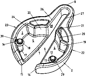
One embodiment and its use will be described more closely in the
following, with reference to the drawing:
s Figure 1 shows the foil cutter, in particular for wine bottles, from above
in
perspective;
Figure 2 shows the foil cutter from below in perspective;
Figure 3 shows a view from above of the foil cutter from above;
Figure 4 shows a side view of the foil cutter;
io Figure 5 shows a front view of the foil cutter;
Figure 6 shows a rear view of the foil cutter;
Figure 7 is a view of the foil cutter from below;
Figure 8 is a section along the line VIII - VIII of Figure 7.
Figure 1 shows the foil cutter 1 for wine bottles in a perspective view from
is above. The foil cutter has finro curved sides 2, 3 and, connected to these,
cover
parts 4, 5, the cover part 4 being connected to the side part 2 and the cover
part 5
being connected to the side part 3. The terminating edges 6 and 7 of the cover
parts 4 and 5 run bent, arc-shaped, in the front part. In the rear connecting
part 8,
the terminating edges 9 and 10 run parallel in the tensioned state of the foil
cutter.
2o Upon pressing together of the two side parts 2 and 3, the connecting part 8
exerts
a spring effect. Two little cutting wheels 12 with round cutting edges 13 are
disposed below on the cover parts 4 and 5, in their front region, on bolt-
shaped
mountings 11. Only one little wheel is visible in Figure 1. The side parts 2
and 3
are limited by edges 14 and 15 on their front ends.
2s The underside of the foil cutter 1 can be seen in Figure 2 in a perspective
view from above. Also visible in Figure 2 is the second little cutting wheel
16 with
the bolt-shaped mounting 17 and the round cutting edge 18. A group of three
crosspieces, connected to the side part and/or to the cover part on the half
side
22 of the foil cutter, and a group of three further crosspieces 24, 25, 26,
disposed
3o symmetrically with respect to the first-mentioned crosspieces and connected
to
the side part 3 and/or cover part 5 on the other half side 23 of the foil
cutter, each
form a profile section with an inner-situated plastic support 20 or 25 and
make up

CA 02320432 2000-09-21
3
direct rests for the neck of the bottle, exercising, on the one hand, a
supporting
function, but at the same time being so designed that as little friction as
possible
arises during turning of the foil cutter. The two halves 22 and 23 of the foil
cutter
are disposed symmetrically to a plane running parallel to the longitudinal
surtaces
s 27 and 28 of the connecting part 8. The cutting edges 13 and 18 on the
little
cutting wheels 12 and 16 have been turned by 180° compared to the state
of the
art so that placement on the bottle is made easier. The cutting edges 13, 18
are
disposed adjacent to the mountings 11, 17. To cut off the foil of a wine
bottle, the
foil cutter is placed on the upper rim of the bottle, the rests 20 and 25
lying
io against the foil to be cut. The foil cutter is then pressed together on the
side parts
2 and 3 so that the cutting edges 13 and 18 of the two little cutting wheels
disposed in each of the halves 22, 23 engage the foil, the foil cutter being
turned
until the upper cap of the two foil enclosures can be removed. The side parts
2
and 3 are provided with indentations 29 and 30 in the region of the little
cutting
is wheels.
Figure 3 is a view of the foil cutter from above. In particular, the
symmetrical arrangement of the halves 22 and 23 can be seen. The two halves
22 and 23 are disposed in a resilient way with respect to the connecting part
8 of
the foil cutter.
2o Figure 4 shows a side view of the foil cutter.
Figure 5 shows a front view of the foil cutter.
Figure 6 shows a rear view of the foil cutter, the rear limit 31 of the
connecting part 8 being visible.
Figure 7 shows a view of the foil cutter from below.
Zs Figure 8 shows a section along the line VIII - VIII of Figure 7. The axes
32
and 33 of the little cutting wheels 12 and 16 are also visible in Figure 8.
The foil cutter is preferably made of plastic and the little cutting wheels of
metal.

Representative Drawing
A single figure which represents the drawing illustrating the invention.
Administrative Status

2024-08-01:As part of the Next Generation Patents (NGP) transition, the Canadian Patents Database (CPD) now contains a more detailed Event History, which replicates the Event Log of our new back-office solution.

Please note that "Inactive:" events refers to events no longer in use in our new back-office solution.

For a clearer understanding of the status of the application/patent presented on this page, the site Disclaimer , as well as the definitions for Patent , Event History , Maintenance Fee  and Payment History  should be consulted.

Event History

Description Date
Application Not Reinstated by Deadline 2006-09-21
Time Limit for Reversal Expired 2006-09-21
Inactive: IPC from MCD 2006-03-12
Deemed Abandoned - Failure to Respond to Maintenance Fee Notice 2005-09-21
Inactive: Abandon-RFE+Late fee unpaid-Correspondence sent 2005-09-21
Application Published (Open to Public Inspection) 2001-03-24
Inactive: Cover page published 2001-03-23
Inactive: First IPC assigned 2000-12-01
Application Received - Regular National 2000-10-24
Filing Requirements Determined Compliant 2000-10-24
Letter Sent 2000-10-24
Inactive: Filing certificate - No RFE (English) 2000-10-24

Abandonment History

Abandonment Date Reason Reinstatement Date
2005-09-21

Maintenance Fee

The last payment was received on 2004-07-22

Note : If the full payment has not been received on or before the date indicated, a further fee may be required which may be one of the following

  • the reinstatement fee;
  • the late payment fee; or
  • additional fee to reverse deemed expiry.

Please refer to the CIPO Patent Fees web page to see all current fee amounts.

Fee History

Fee Type Anniversary Year Due Date Paid Date
Registration of a document 2000-09-21
Application fee - standard 2000-09-21
MF (application, 2nd anniv.) - standard 02 2002-09-23 2002-07-23
MF (application, 3rd anniv.) - standard 03 2003-09-22 2003-07-16
MF (application, 4th anniv.) - standard 04 2004-09-21 2004-07-22
Owners on Record

Note: Records showing the ownership history in alphabetical order.

Current Owners on Record
ZYLISS HAUSHALTWAREN AG
Past Owners on Record
HANS WEIBEL
Past Owners that do not appear in the "Owners on Record" listing will appear in other documentation within the application.
Documents

To view selected files, please enter reCAPTCHA code :


To view images, click a link in the Document Description column. To download the documents, select one or more checkboxes in the first column and then click the "Download Selected in PDF format (Zip Archive)" or the "Download Selected as Single PDF" button.

List of published and non-published patent-specific documents on the CPD .

If you have any difficulty accessing content, you can call the Client Service Centre at 1-866-997-1936 or send them an e-mail at CIPO Client Service Centre.


Document
Description 
Date
(yyyy-mm-dd) 
Number of pages   Size of Image (KB) 
Representative drawing 2001-03-12 1 13
Cover Page 2001-03-12 1 35
Abstract 2000-09-21 1 17
Claims 2000-09-21 1 33
Description 2000-09-21 3 149
Drawings 2000-09-21 4 91
Courtesy - Certificate of registration (related document(s)) 2000-10-24 1 120
Filing Certificate (English) 2000-10-24 1 163
Reminder of maintenance fee due 2002-05-22 1 111
Reminder - Request for Examination 2005-05-25 1 116
Courtesy - Abandonment Letter (Maintenance Fee) 2005-11-16 1 176
Courtesy - Abandonment Letter (Request for Examination) 2005-11-30 1 166