Note: Descriptions are shown in the official language in which they were submitted.
CA 02320588 2000-09-26
PPC-0717
ULTRATHIN FLUID MANAGEMENT ARTICLE
Field of the Invention
The present invention relates to an extremely thin, fluid management article
that is
intended to be worn adjacent a user's perineum. The article is useful in
collecting and / or
absorbing low volumes of bodily fluids, such as menses, urine, and
perspiration.
Background of the Invention
Externally worn absorbent articles for managing discharged bodily fluids are
well
to known in the art. A plethora of design features have evolved over the years
in an effort to
improve the performance of these articles, such as lateral extensions for
wrapping around
a user's undergarment, body-conforming means for diminishing any gaps between
the
article and the user's body, and the addition of highly absorbent and
retentive materials,
such as those materials commonly referred to as superabsorbents. An additional
15 evolutionary aspect of these articles, is a reduction in article thickness
(caliper).
The designers of the reduced caliper articles referred to above have
maintained
the absorptive capacity of the relatively thicker articles being replaced,
thereby providing
users with a thin and flexible article capable of managing significant volumes
of fluid.
For example Osborne, III, US Pat. No. 4,950,264, discloses a thin and flexible
sanitary
2o napkin having a capacity great enough to handle medium to high menstrual
flows. The
napkins in '264 have a preferred caliper of less than about 2.6 millimeters
and total fluid
capacity of at least about 20.0 grams. Brandt et al., US Pat. No. Re. 32,649,
discloses
absorbent articles comprising an intimate admixture of hydrophilic fiber
material and
hydrogel-forming particles, purportedly capable of holding high amounts of
discharged
2s body fluids.
More and more consumers are purchasing and wearing fluid management articles
on an everyday basis, as compared to only during their menstrual period.
Consumers may
experience daily perspiration, vaginal discharge, post intercourse drainage,
and other fluid
discharges due to various conditions, such as infection. To manage the daily
discharge
3o and to feel "fresh", consumers must purchase and wear standard napkins or
panty liners,
dealing with the obtrusiveness and high absorptive capacity associated with
these
products. While articles such as those disclosed in '264 and '649 are suitable
for
managing significant volumes of fluid, they are overdesigned for managing low
volumes,
such as those encountered intermenstrually. Even the least absorbing articles
CA 02320588 2000-09-26
commercially available in the US, such as CAREFREE panty liners and KOTEX
LIGHTDAYS pantiliners, offer excess absorption capacity for light menstrual
flow and
intermenstrual discharge.
One approach to address managing low volumes of bodily fluids is disclosed in
Boisse et al., US Pat. No. 5,613,963. The article disclosed in '963 is a panty
liner,
consisting essential of a unitary sheet of nonwoven fabric constituting a
primary liquid-
retaining component and plurality of recesses on its top surface, and a liquid-
impervious
barrier layer. Boisse et al. teaches constructing the nonwoven fabric from a
mixture of
fiber types, with rayon fibers being a constant in the multitude of
combinations. A
1o disadvantage realized with this construction is that the rayon fibers are
absorbent, and
therefore may retain fluid at or near its skin-contacting surface. If the
outer surface feels
clammy to a user, then discomfort occurs, with an extreme case impelling the
user to
replace the article before its useful life has terminated.
What is still needed is a thin and flexible fluid management article that
provides
t5 extreme comfort and adequate capacity for collecting and / or absorbing
limited volumes
of bodily fluid.
Summary of the Invention
The present invention relates to a fluid management article to be worn
adjacent a
2o user's perineum for collecting and / or absorbing low volumes of bodily
fluids
encountered both menstrually and intermenstrually. The article is particularly
useful for
everyday use, that is, for managing daily perspiration, vaginal discharge,
post intercourse
drainage, and other bodily fluids due to various conditions, such as
infection.
In accordance with one embodiment of the present invention, a fluid management
25 article designed and configured to be worn adjacent a user's perineum,
comprising an
absorbent-free, liquid permeable structure having a first surface and a second
surface
opposite thereof; and a barrier layer covering at least a portion of the
second surface, is
provided. These articles being substantially free of absorbent material will
collect fluid
within the interstitial spaces (pores), to prevent fluid from transferring to
unwanted
30 surfaces.
In accordance with a second embodiment of the present invention, a fluid
management article designed and configured to be wom adjacent a user's
perineum,
comprising a liquid permeable cover; a barrier layer; and an absorbent core
intermediate
2
CA 02320588 2000-09-26
the cover and the barrier layer; wherein the article has a total capacity of
1.2 grams or
less, is provided.
In accordance with a third embodiment of the present invention, a fluid
management article designed and configured to be worn adjacent a user's
perineum,
comprising a liquid permeable cover; a barrier layer; and an absorbent core
intenmediate
the cover and the barrier layer; the absorbent core comprising 0.7 grams or
less of
absorbent material, is provided. Preferably, the absorbent material is
substantially free of
hydrogel-forming polymers.
to Brief Description of the Drawings
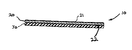
FIG.1 is an end view of a fluid management article provided by the present
invention having a liquid permeable structure and a barrier layer overlaying a
garment-
facing side of the structure.
FIG.2 is an end view of the fluid management article of FIG.1 depicting an
t5 optional cover overlaying a body-facing side of the structure.
FIG. 3 is a cutaway perspective view of a fluid management article provided by
the present invention having a liquid permeable cover, a barrier layer, and an
absorbent
core intermediate the cover and barrier.
2o Detailed Description of the Invention
The present invention relates to a fluid management article designed and
configured to be worn adjacent a user's perineum, that is useful for
collecting and / or
absorbing low volumes of bodily fluids. Referring to FIG. 1, in a preferred
embodiment,
fluid management article 10 consists essentially of an absorbent-free, liquid
permeable
25 structure 20 having a first surface 21 to be worn facing the user's body
and an opposing
second surface 22 (garment-facing); and a barrier layer 30 covering at least a
portion of
the second surface 22. The liquid permeable structure 20 may exhibit the
following, non-
limiting configurations, a nonwoven web, a woven web, an apertured film, an
apertured
formed film, a substrate having flocked fibers thereon, a lamination of
multiple layers of
3o films or fibrous webs and combinations thereof, or the like. The absorbent-
free, liquid
permeable structure 20 is capable of collecting fluid within existing
interstitial spaces (or
pores), such as for example between non-absorbent fibers or within apertures /
bosses.
Any collected fluid will have a tendency to settle proximal the barrier layer
30, thereby
minimizing fluid retention proximal the body-facing surface 21.
CA 02320588 2000-09-26
A liquid permeable structure in the form of flocked fibers may have a liquid
permeable or impermeable carrier, such as a nonwoven web or a polymeric filin.
The
carrier may comprise hydrophilic fibers, hydrophobic fibers, or combinations
thereof.
Methods of flocking onto a substrate are known in the art of fabric
manufacture. See for
example, US Pat. Nos. 3,436,442 and 3,679,929. In addition, European Pat. App.
No.
737,462 discloses an absorbent article having flocked fibers on its external
surface.
Examples of apertured films and apertured formed films usefi~l as the liquid
permeable structure are disclosed in the following US Pat. Nos. 4,710,186 and
4,342,314.
Nonwoven webs are preferred as the absorbent-free, liquid permeable structure
20. Suitable fibers useful for making such nonwoven webs include polyolefin
and
polyester fibers. A polypropylene nonwoven web is particularly suitable for
the liquid
permeable structure 20, wherein the polypropylene fibers making up the web are
preferably of at least two different deniers, such as 3 and 5 denier fibers.
The nonwoven
webs have a basis weight from about 20 to about 200 grams per square meter,
preferably
t 5 from about 30 to about I 00 grams per square meter.
Raw materials, such as individual fibers, that are used in the manufacture of
the
liquid permeable structure 20, or alternatively the structure's first and
second surface 21
and 22 respectively, may optionally be treated with a surface active agent to
render the
structure more hydrophilic or hydrophobic. To help draw any captured fluid
away from a
2o user's body, that is from the first surface 21, the second surface 22 for
example may be
treated to render it more hydrophilic. In contrast, the second surface 22 may
be treated
with various fluid repellants to render it significantly hydrophobic to help
prevent any
captured fluid from transferring to the user's undergarments or other unwanted
surfaces.
The barrier layer 30 can be of any flexible material that prevents and / or
retards
25 the through transfer of liquid but does not necessarily prevent the passage
of gases.
Commonly used materials are polyethylene or polypropylene films. The barrier
layer may
also be an extruded thermoplastic coating, that is directly extruded onto at
least portions
of the second surface 22, such as disclosed in Sonoda, US Pat. No. 5,089,075.
Adhesive
coatings, for positioning article 10 in a user's undergarments, may also serve
as the
3o barrier layer 30, as described in greater detail below.
Other materials that may be used as the barrier layer are made from those
selected
from films of polyesters, polyamides, ethylene vinyl acetate, polyvinyl
chloride,
polvvinylidene chloride, cellophane, nitrocellulose and cellulose acetate. Co-
extruded
and laminated combinations of the foregoing, wherein such combinations are
permitted
4
CA 02320588 2000-09-26
by the chemical and physical properties of the film. may be used. Liquid
impermeable
reticulated foams and repellent treated papers may also be used.
Barrier layers that block or retard liquid permeation, but permit gases to
transpire,
i.e., "breathable barriers", may be used. Single or multiple layers of
microporous films,
fabrics and combinations thereof, that provide a tortuous path, and/or whose
surface
characteristics provide a liquid repellent surface to the penetration of
liquids may be used
to provide such breathable barriers. A nonwoven web particularly useful as a
breathable,
barrier layer is a spunbond polypropylene web, providing a retarding effect,
but not
necessarily an absolute barrier, to liquid strikethrough.
1o Attachment means may occupy portions of the first surface 21 and/or the
outwardly disposed surface of the barrier layer 30. Body-adhesives, such as
those
disclosed in Sieverding, US Pat. No. 4,883,193, may be applied to the first
surface 21 for
attaching the liquid permeable structure 20 directly to a user's body.
Alternatively,
positioning adhesives, mechanical fasteners, or high coefficient of friction
materials may
be applied to the barrier layer 30 for releasably adhering the liquid
permeable structure 20
to a user's undergarments or hosiery. Alternatively, the barrier layer itself
may be -
constructed from a high coefficient of friction material, such as natural or
synthetic
rubber, thereby eliminating the need for additional material to provide
undergarment
attachment. Useful mechanical fasteners and high coefficient of friction
materials are
2o disclosed in the following US Pat. Nos. 4,946,527; 5,058,247; 4,166,464;
and 5,011,480.
Preferably, positioning adhesives are used to adhere the article 10 to a
user's
undergarments. Positioning adhesives suitable for the articles of the present
invention are
well known in the art, one known class being styrenic block copolymers.
Techniques used
for applying the adhesives to the article include, but are not limited to slot
coating,
spraying, knife coating, extrusion coating, and transfer coating. The
adhesives may also
be foamed prior to application, such as by using commercially available
equipment from
the Nordson Corporation. Adhesives may be coated in continuous or in discrete
patterns
from emulsion or solution directly onto the product substrate or onto a
release substrate to
be subsequently transferred onto the article.
3o Positioning adhesives may serve as a barrier or repellent to liquid
permeation.
Puletti et al., US Pat. No. 4,692,161, discloses a hot melt adhesive waste
barrier.
Embodiments of '161 include coating portions, or all of a nonwoven web with
pressure
sensitive formulations, so as to form a barrier to replace conventionally
employed
impermeable films and separate attachment means.
5
CA 02320588 2000-09-26
As shown in FIG. 2, fluid management article 10 may optionally employ a liquid
permeable cover 40, overlaying the first surface 21. The cover 40 is
preferably compliant,
soft feeling, and non-irritating to a user's skin. The cover should further
exhibit good
strikethrough and a reduced tendency to rewet, permitting bodily discharges to
rapidly
penetrate it and flow toward subsequent underlying layers, while not allowing
such
discharges to flow back through the cover to the skin of the user.
A suitable cover 40 may be manufactured from a wide range of materials
including, but not limited to woven and nonwoven fabrics, apertured formed
polymeric
films, hydro-formed films, porous foams, reticulated foams, reticulated
thermoplastic
to films, and thermoplastic scrims. In addition, the cover may be constructed
from a
combination of one or more of the above materials, such as a composite layer
of
nonwoven and apertured formed thermoplastic film. Apertured filins are well
suited for
the cover 40 because they are pervious to liquids and, if properly apertured
(including
tapering), have a reduced tendency to allow liquids to pass back through and
rewet the
~5 user's skin. Useful films are disclosed in the following US Pat.
Nos.3,929,135; 4,324,426;
4,342,314; 4,463,045; and 5,006,394.
Particularly suitable covers 40 include 30 and 34 grams per square meter
versions
of a thermobonded multidenier (3 and 5 denier) polypropylene nonwoven web, and
14
and 18 grams per square meter versions of a through-air nonwoven comprising
2o polyethylene sheath and polypropylene core bi-component fibers.
The liquid permeable cover 40 may employ body adhesives on its outwardly
disposed surface for attaching the article 10 directly to a user's body. The
article can be
attached to pubic hair covered parts of the perineum, such as the mons pubis
and the
vulva. Alternatively, the article can be attached to relatively hairless
parts, such as the
25 inner surfaces of the labia majors, the labia minors, and the inward
surfaces of the thighs
and the cleft between the thighs and the perineum. Multiple areas of body
attachment are
also provided by the present invention.
FIGS. 1 and 2 and their corresponding description, illustrate preferred
embodiments of a first approach to managing low volumes of bodily fluids while
3o maintaining user comfort, wherein the fluid management article 10 contains
zero
absorbent material. The first approach or substantial equivalents thereto,
provide a
comfort improvement over the existing art by minimizing the potential for
fluid retention
at or near the skin-contacting surface. Captured fluid will tend to permeate
the interstitial
spaces (pores) and settle distal the skin-contacting surface.
6
CA 02320588 2000-09-26
A second approach to managing low volumes of fluid, while maintaining user
comfort, employs limited amounts of absorbent material in a core layer, which
is buffered
from skin contact by a liquid permeable cover. FIG. 3 depicts preferred
embodiments
relating to the second approach. Fluid management article 10 comprises a
liquid
permeable cover 40, a barrier layer 30, and an absorbent core 50 intermediate
the cover
and barrier. The liquid permeable cover 40 and the barrier layer 30 are shown
to extend
beyond the absorbent core 50. The absorbent core may alternatively, be
coterminous with
the cover and barrier. Preferably, the absorbent core 50 contains absorbent
material in an
amount of 0.70 grams or less.
to A representative, non-limiting list, of absorbent material useful in the
absorbent
core 50 includes natural cellulosics, such as cotton and wood pulp;
regenerated
cellulosics, such as rayon and cellulose acetate; peat moss; hydrogel-forming
polymers in
the fonm of fibers or particles, commonly referred to as "superabsorbents";
and the like.
One of ordinary skill in the art would readily appreciate that a blend of two
or more types
15 of absorbent materials may be used to optimize the performance of fluid
management
articles used in varying conditions. The absorbent material may be uniformly
dispersed
within the core 50, or may alternatively be placed in discrete patterns, or in
gradients. For
example, in an effort to help reduce side leakage, absorbent material may be
placed in
high concentrations around peripheral portions of the core.
2o The absorbent core 50 may have a blend of absorbent materials and
thermoplastic
fibers, for example to provide structural integrity to the formed structure or
for heat
sealability to additional layers, such as a barrier layer film. Useful
thermoplastic fibers
are polyolefins, such as polypropylene and polyethylene fibers. The
thermoplastic fibers
may be bi-component or mufti-component fibers having a first component having
a first
25 melting temperature and two or more additional components having different
melting
temperatures to that of the first melting temperature. Bi-component fibers are
typically
configured sheath-core or side-by-side. Suitable bi-component fibers include
polyester /
polyethylene and polypropylene / polyethylene
A Preferred absorbent core 50 comprises a composite of cellulosic fibers and
3o thermoplastic binder fibers, having a basis weight in the range from about
50 to about 200
grams per square meter. When the absorbent core 50 comprises hydrogel-forming
polymers (superabsorbents) as the absorbent material, they will preferably be
in quantities
significantly less than 0.70 grams, on the order of 0.3 grams or less such
that the article
7
CA 02320588 2000-09-26
does not offer excess absorbent capacity. Absorbent capacities are discussed
in more
detail below.
Similar to the embodiments described in conjunction with FIGS. 1 and 2,
embodiments corresponding to FIG. 3 may contain attachments means on the
outwardly
disposed surfaces of the barrier layer 30 and/or the cover 40.
The individual layers of the present invention may employ any known assembly
techniques for adhering adjacent layers together. A representative, non-
limiting list of
assembly techniques and materials, includes adhesives, heat seal, ultrasonic
welding,
solvent welding, and mechanical fastening. Preferably, construction adhesives
are used
to to laminate individual elements to one another. Suitable construction
adhesives are
disclosed in the following US Pat. Nos. 4,526,577; 5,149,741; and 5,057,571.
The
construction adhesives may be modified to be absorbing by incorporating
absorbing
polymer into their fonmulations.
The fluid management articles of the present invention are intended to manage
low volumes of fluid encountered both menstrually, and intenmenstrually.
Preferably, the
various embodiments of the present invention have a total capacity of 1.2
grams or less,
as determined by the total capacity test defined in the test methods section.
In addition to fluid capacity, the articles of the present invention are
designed to
be extremely comfortable and non-obtrusive to a user. The collective design
attributes
2o are intended to provide daily confidence without compromise to lifestyle,
including
activity and clothing. Two variables, which may affect the before mentioned
design
characteristics, are article caliper and flexibility. Preferably the articles
have a caliper of
3.0 millimeters or less, more preferably 2.0 millimeters or less, and most
preferably 1.1
millimeters or less. Flexibility is measured by a flexural resistance test,
described in great
detail in the test methods section. Preferably, the articles have a flexural
resistance of 120
grams or less.
The articles of the present invention are also useful for delivering a
multitude of
additives. A representative, non-limiting list of potential additives includes
medicaments, moisturizers, vitamins and minerals, spermicides, and odor
controlling
3o agents.
The articles may be of any shape suitable for placement against a user's
perineum
and the surrounding areas. Shapes include rectangular, oval, dogbone, peanut
shape, and
the like.
CA 02320588 2000-09-26
In addition to the elements specifically disclosed in the instant
specification, other
performance enhancers known in the art may be employed, such as lateral
extensions for
wrapping around a crotch portion of user's undergarments.
To help prevent fluid leakage from the peripheral portions of the articles,
the
individual elements themselves, or the finished article, may employ
embossments in the
form of discrete densified areas or channels.
The articles of the present invention may be individually wrapped in a flat,
folded,
or rolled configuration for easy portability. The individual wrappings may
employ
features that render the wrapper useful as a disposal means for soiled
articles.
1o The preparation and properties of fluid management articles according to
the
present invention are further illustrated by the following examples. The
examples are
given for the purposes of illustration only and the invention is not limited
thereto.
le A: fluid management articles were constructed comprising a 18 gsm
15 nonwoven cover consisting of polypropylene / polyethylene bi-component
fibers, a 65
gsm absorbent core consisting of airlaid pulp and an acrylic binder, and a
24.5 gsm
polyethylene film barrier. Fuller HL-1491XZP hot melt construction adhesive
was used to
adhere adjacent elements. Fuller 1417 positioning adhesive was placed onto the
garment-
facing surface of the film barrier. The pulp was the only absorbent material
present in the
20 articles, at a level of 0.40grams. The articles had an average caliper of
0.96 millimeters,
flexural resistance of 34.23 grams, and total capacity of 1.34 grams.
am le B: fluid management articles may be prepared as follows. Provide a 34
gsm nonwoven web as a liquid permeable structure, wherein the web comprises 3
and 5
25 denier polypropylene fibers. Provide a 0.8 mil polyethylene film as a
barrier layer.
Adhere the liquid permeable structure to the barrier layer with a styrenic
block copolymer
adhesive formulation. The article is void of any absorbent material.
c 1 ,~: fluid management articles may be prepared as follows. Provide a 34
3o gsm nonwoven web as a liquid permeable cover, wherein the web comprises 3
and 5
denier polypropylene fibers. Provide a 0.8 mil polyethylene film as a barrier
layer.
Pmvide a 50 gsm nonwoven web as a liquid penmeable structure, wherein the web
comprises 12 denier polyester fibers. Place the liquid permeable structure
intermediate the
CA 02320588 2000-09-26
cover and barrier and adhere the elements with a styrenic block copolymer
adhesive
formulation. The article is void of any absorbent material.
Test Methods
The total capacity of a fluid management article is determined as follows. Any
individual wrapping materials and adhesive release paper is removed from the
article to
be tested. The article is first weighed to the nearest 0.1 gram. The article
is then
submerged in a container of 1 % saline solution, such that the article is
totally submerged
and is not bent or otherwise twisted or folded. The article remains submerged
for 10
1o minutes. It is then removed from the saline and suspended for two minutes
in a vertical
position to allow the saline to drain out of the article. The article is then
placed body -
facing surface down onto an absorbent blotter, such as Whatmann grade # 1
filter paper
available from VWR Scientific of Bridgeport, NJ. A uniform 17.6 grams per
square
centimeter load is placed over the article to squeeze excess saline out. The
absorbent
~5 blotter material is replaced every 30 seconds until the amount of saline
transferred to the
absorbent blotter is less than 0.5 grams in a 30-second period. Next, the
article is
weighed to the nearest 0.1 gram and the initial weight of the article is
subtracted. The
difference in grams is the total capacity of the article.
The flexural resistance of the article is measured by peak bending stiffness.
Peak
2o bending stiffness is determined by a test that is modeled after the ASTM D
4032.82
CIRCULAR BEND PROCEDURE, the procedure being considerably modified and
performed as follows. The CIRCULAR BEND PROCEDURE is a simultaneous multi-
directional deformation of a material in which one outwardly disposed surface
of the
article becomes concave and the opposing surface becomes convex. The CIRCULAR
25 BEND PROCEDURE yields a force value related to flexural resistance,
simultaneously
averaging stiffness in all directions.
The apparatus required for measuring flexural resistance is a modified
Circular
Bend Stiffness Tester, having the following parts: A smooth-polished steel
plate platform
that measures 102.0 X 102.0 X 6.35 millimeters, having an 18.75 millimeter
diameter
30 orifice. The lap edge of the orifice should be at a 45 degree angle to a
depth of 4.75
millimeters. A plunger having an overall length of 72.2 millimeters, a
diameter of 6.25
millimeters, a ball nose having a radius of 2.97 millimeters and a needle-
point extending
0.88 millimeter therefrom having a 0.33 millimeter base diameter and a point
having a
radius of less than 0.5 millimeter. The plunger is mounted concentric with the
orifice,
t0
CA 02320588 2000-09-26
having equal clearance on all sides. A force-measurement gauge and more
specifically an
Instron inverted compression load cell. The load cell has a load range of from
about 0.0
to about 2,000.0 grams. An actuator, and more specifically the Instron Model
No. 1122
having an inverted compression load cell. The Instron instrument is made by
the Instron
Engineering Corporation, Canton, Mass.
Specimens are cut from the articles to be tested, measuring 37.5 X 37.5
millimeters. The specimens should be cut inward from the periphery in order to
ensure
that all of the elements of the article are maintained within the specimens.
Any individual
wrapping and release paper is removed before testing. Any undergarment or body
1o adhesive should be blocked, such as by applying powder to the adhesive, in
an effort to
prevent the specimens from adhering to the platform, resulting in an
artificially high test
value. The plate is leveled and the plunger speed is set at 50.0 centimeters
per minute per
full stroke length. A specimen is centered on the orifice below the plunger
such that the
body-facing surface is facing the platform. The plunger is then actuated and
the
15 maximum force reading to the nearest gram is recorded. Preferably, multiple
specimens
are cut from a single article and measured, with the average maximum force
readings
representing the flexural resistance of the article.
The caliper of the article is measured through the use of a comparator gauge,
such
as those available from the B.C. Ames, Company of Waltham, Mass. The
comparator
2o gauge should have a 28.6 millimeters (1 1/8 in.) diameter comparator foot.
The
comparator gauge is zeroed. A 56.7 grams (2 oz.) weight is placed on the
spindle
extending above the comparator dial. The comparator foot is raised and the
article, with
any individual wrapping and release paper removed, is placed garment-facing
surface
down on the base plate. The article is positioned on the base plate so that
when the foot is
25 lowered it is in the center of the article. The foot is gently lowered onto
the article. The
article caliper is determined by reading the comparator dial after the foot
comes into
contact with the article and the output value is stable (if using digital
model is used). The
measurement is repeated at each of the ends of the article along its
longitudinal centerline.
The average of the measurements is the caliper of the article.
3o The disclosures of all patents, as well as any corresponding published
foreign
patent applications, mentioned throughout this patent application are hereby
incorporated
by reference herein.
The specification and embodiments above are presented to aid in the complete
and
non-limiting understanding of the invention disclosed herein. Since many
variations and
11
CA 02320588 2000-09-26
embodiments of the invention can be made without departing from its spirit and
scope,
the invention resides in the claims hereinafter appended.
12