Language selection

Search

Patent 2320662 Summary

Third-party information liability

Some of the information on this Web page has been provided by external sources. The Government of Canada is not responsible for the accuracy, reliability or currency of the information supplied by external sources. Users wishing to rely upon this information should consult directly with the source of the information. Content provided by external sources is not subject to official languages, privacy and accessibility requirements.

Claims and Abstract availability

Any discrepancies in the text and image of the Claims and Abstract are due to differing posting times. Text of the Claims and Abstract are posted:

  • At the time the application is open to public inspection;
  • At the time of issue of the patent (grant).
(12) Patent: (11) CA 2320662
(54) English Title: POWER ADJUSTMENT SIZE INDICATOR FOR A DOOR CLOSER
(54) French Title: INDICATEUR DE DIMENSIONS POUR REGLAGE DE PUISSANCE D'UN FERME-PORTE
Status: Term Expired - Post Grant Beyond Limit
Bibliographic Data
(51) International Patent Classification (IPC):
  • E05F 03/22 (2006.01)
  • E05F 03/10 (2006.01)
(72) Inventors :
  • BISHOP, ARTHUR (United Kingdom)
  • BRAUNLICH, MARK (United States of America)
  • BLANFORD, THOMAS H. (United States of America)
  • WASIELEWSKI, MICHAEL (United States of America)
(73) Owners :
  • INGERSOLL-RAND ARCHITECTURAL HARDWARE GROUP LIMITED
  • SCHLAGE LOCK COMPANY LLC
(71) Applicants :
  • INGERSOLL-RAND ARCHITECTURAL HARDWARE GROUP LIMITED (United Kingdom)
  • SCHLAGE LOCK COMPANY LLC (United States of America)
(74) Agent: NORTON ROSE FULBRIGHT CANADA LLP/S.E.N.C.R.L., S.R.L.
(74) Associate agent:
(45) Issued: 2007-03-13
(22) Filed Date: 2000-09-26
(41) Open to Public Inspection: 2001-04-15
Examination requested: 2003-12-10
Availability of licence: N/A
Dedicated to the Public: N/A
(25) Language of filing: English

Patent Cooperation Treaty (PCT): No

(30) Application Priority Data:
Application No. Country/Territory Date
09/419,420 (United States of America) 1999-10-15

Abstracts

English Abstract

A gear driven dial indicator is used to indicate the door closer size for a door closer having an adjustable closing force. A drive gear is attached to the door closer adjustment screw. In the preferred embodiment, this drive gear engages a ring gear which is formed as part of the dial indicator. As the door closer adjustment screw is turned to change the door closer size, the drive gear turns with the adjustment screw. The drive gear then turns the planetary gear which turns the dial indicator, thereby changing the indicated size of the door closer.


French Abstract

Comparateur à cadran entraîné par engrenage et utilisé pour indiquer la taille de dispositif ferme-porte pour un dispositif ferme-porte ayant une force de fermeture ajustable. Un engrenage d'entraînement est attaché à la vis d'ajustement de dispositif ferme-porte. Dans le mode de réalisation préféré, cet engrenage d'entraînement met en prise une couronne qui est formée comme partie intégrante du comparateur à cadran. A mesure que la vis d'ajustement de dispositif ferme-porte tourne pour modifier la taille de dispositif ferme-porte, l'engrenage d'entraînement tourne avec la vis d'ajustement. L'engrenage d'entraînement fait alors tourner la couronne qui fait tourner le comparateur à cadran, modifiant ainsi la taille indiquée du dispositif ferme-porte.

Claims

Note: Claims are shown in the official language in which they were submitted.

CLAIMS,
1. A size indicator for use with a door closer having a
rotary adjustable closing force means, the size indicator
comprising:
a rotatable dial indicator substantially surrounding
the rotary adjustable closing force means, the rotatable
dial indicator having a plurality of indicia thereon; and
a gear assembly operably connecting the rotary
adjustable closing force means to the rotatable dial
indicator.
2. The size indicator according to claim 1, wherein the
gear assembly includes the rotatable dial indicator
comprising a ring gear having gear teeth on an inner
circumference of the ring gear.
3. The size indicator according to claim 2, wherein the
gear assembly further includes a drive gear attached to the
rotary adjustable closing force means.
4. The size indicator according to claim 3, wherein the
drive gear is a double-toothed gear.
5. The size indicator according to claim 3, wherein the
gear assembly further includes a planetary gear driven by
the drive gear, the planetary gear driving the ring gear.
6. The size indicator according to claim 2, wherein the
rotatable dial indicator rotates about an indicator axis,
which is offset from a closing means axis around which the
rotary adjustable closing force means rotates.
-8-

7. The size indicator according to claim 2, wherein the
rotatable dial indicator rotates about an indicator axis,
which is coaxial with a closing means axis around which the
rotary adjustable closing force means rotates.
8. A size for use with a door closer having a rotary
adjustable closing force means, the size indicator
comprising:
a rotatable dial indicator positioned about the
rotary adjustable closing force means, the rotatable dial
indicator having a plurality of indicia thereon and
comprising a ring gear having gear teeth on an inner
circumference; and
a gear assembly operably connecting the rotary
adjustable closing force means to the rotatable dial
indicator, the gear assembly including a drive gear attached
to the rotary adjustable closing force means.
9. The size indicator according to claim 8, wherein the
gear assembly further includes a planetary gear driven by
the drive gear, the planetary gear driving the ring gear.
10. In combination:
a door closer, the door closer having a rotatable
closing pre-load adjustment means; and
a pre-load adjustment indicator comprising: a
rotatable dial indicator attached to an end of the door
closer and positioned about the rotatable closing pre-load
adjustment means, the rotatable dial indicator having a
plurality of indicia thereon and comprising a ring gear
having gear teeth on an inner circumference of the ring
gear; and a drive gear attached to the rotatable closing
pre-load adjustment means, the drive gear being operably
connected to the rotatable dial indicator ring gear.
-9-

11. The combination according to claim 10, further
comprising a planetary gear driven by the drive gear, the
planetary gear driving the ring gear.
12. The combination according to claim 10, wherein the
rotatable dial indicator rotates about an indicator axis,
which is offset from a closing means axis around which the
rotary adjustable closing force means rotates.
13. The combination according to claim 10, wherein the
rotatable dial indicator rotates about an indicator axis,
which is coaxial with a closing means axis around which the
rotary adjustable closing force means rotates.
-10-

Description

Note: Descriptions are shown in the official language in which they were submitted.


CA 02320662 2000-09-26
POWER ADJUSTMENT SIZE INDICATOR FOR A DOOR CLOSER
BACKGROUND OF THE INVENTION
This invention relates generally to door closers and
more particularly to door closers having a means for ad-
justing the closing force of the door closer.
Door closers are sized using ANSI 1154 standards or
other international standards. The ANSI standards specify,
among other requirements, the minimum closing force re-
quired for the door to be specified as a size l, 2, 3, 4,
5, or 6. The higher the size, the greater the closing
force of the door closer and thus the door.
Current door closers typically provide a means to in-
crease and decrease this closing force. One prior art ad-
justable door closer is shown in FIG. 1. This is accom-
plished by changing the pre-load on the closer spring. The
adjustment means is typically a screw at the end of the
closer; rotating the screw in one direction increases the
pre-load; rotating in the other direction decreases the
pre-load. Typically, the installation instruction sheet
informs the installer of the number of rotations and the
-1-

CA 02320662 2006-05-03
direction to turn the adjustment screw for specific size
doors.
A problem arises in that as the screw is turned, and
the door closer is adjusted, there is no indicator showing
the ANSI size.
The foregoing illustrates limitations known to exist
in present door closers. Thus, it is apparent that it
io would be advantageous to provide an alternative directed
to overcoming one or more of the limitations set forth
above. Accordingly, a suitable alternative is provided
including features more fully disclosed hereinafter.
SUMMARY OF THE INVENTION
In one aspect of the present invention, this is
accomplished by providing a size indicator for use
with a door closer having a rotary adjustable
2o closing force means, the size indicator comprising: a
rotatable dial indicator substantially surrounding the
rotary adjustable closing force means, the rotatable
dial indicator having a plurality of indicia thereon;
and a gear assembly operably connecting the rotary
-2-

CA 02320662 2000-09-26
adjustable closing force means to the rotatable dial indi-
cator.
The foregoing and other aspects will become apparent
from the following detailed description of the invention
when considered in conjunction with the accompanying draw-
ing figures.
BRIEF DESCRIPTION OF THE DRAWING FIGURES
FIG. 1 shows a prior art door closer;
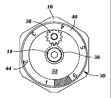
FIG. 2 is a plan view of a door closer power adjust-
ment size indicator with a cover removed;
FIG. 3 is a perspective view of the power adjustment
size indicator shown in FIG. 2 with a portion of the cover
removed; and
FIG. 4 is a plan view of a second embodiment of a door
closer power adjustment size indicator.
-3-

CA 02320662 2000-09-26
DETAILED DESCRIPTION
FIG. 1 shows a typical prior art door closer 10 with
one type of size adjustment mechanism 14. The illustrated
door closer 10 uses a plurality of adjustable power springs
34. The door closer 10 includes a cylinder housing 12 with
removable end caps 16 sealing the ends of the housing 12.
The closer 10 also includes a piston 20 slidably positioned
within the cylinder housing 12. The piston 20 includes a
rack 22 which engages with the gear teeth on a rotatable
pinion 24. A door control arm (not shown) is connected to
the pinion 24 so that opening of a door would cause clock-
wise rotation of the pinion 24. The pinion 24 in turn acts
through the rack 22 to slide the piston 20 to the right
within the cylinder 12, as shown in FIG. 1. A force ap-
plied to the piston 20, such as by springs 34, urging the
piston 20 to the left in FIG. 1 would operate through the
rack 22 and pinion 24 to close the door.
The adjustment mechanism 14 includes a disk 17 adja-
cent one end cap 16. This adjustment mechanism 14 includes
a rotatable screw member 18 which engages the disk 17. As
the screw member 18 is rotated in a first direction, the
disk 17 is moved towards the piston 20, thereby increasing
-4-

CA 02320662 2000-09-26
the pre-load force of the closing springs 34 on the piston
20. Rotating the screw member 18 in the other direction
moves the disk 17 away from the piston 20, thereby decreas-
ing the pre-load force of the closing springs 34 on the
piston 20.
FIGS. 2 and 3 show the preferred embodiment of the
power size adjustment indicator 30 of the present inven-
tion. The power size adjustment indicator 30 is mounted on
an end 16 of door closer 10 positioned about the rotatable
adjustment screw 18. The power size adjustment indicator
30 includes a front cover 32. Mounted within the front
cover 32 is a double-toothed gear 36 which grippingly en-
gages adjustment screw 18, a planetary gear 38 which is ro-
tatably operated by the double-toothed gear 36, and a dial
indicator 40 which has ring gear 41 on its underside, as
shown in FIG. 3, the ring gear 41 being rotatably driven by
the planetary gear 38. The front side of the dial indica-
for 40 includes a plurality of numerals 44 representing the
ANSI door closer sizes 1 through 6. Preferably, the front
cover 32 has a cutout 33 or clear portion through which the
appropriate door size numeral can be seen. Alternatively,
the power size adjustment indicator 30 can be mounted such
that the appropriate door closer size numeral 44 is the one
-5-

CA 02320662 2000-09-26
which is upright when viewed from a person standing on the
floor adjacent the door. Other gear configurations can be
used in place of the double-toothed gear 36, such as a
three-toothed gear, a single-toothed gear or a gear having
teeth about its entire periphery.
In use, when a person desires to change the door
closer size setting of a door closer, the adjustment screw
18 is turned in the appropriate direction. Rotation of the
adjustment screw 18 will increase or decrease the closing
pre-load applied by springs 34. When adjustment screw 18
is turned, double-toothed gear 36 turns also. Once a revo-
lution, the teeth on the double-toothed gear 36 will engage
planetary gear 38 causing planetary gear 38 to rotate. As
planetary gear 38 rotates, dial indicator 40 rotates due to
the engagement of planetary gear 38 with ring gear 41. Af-
ter multiple rotations of the adjustment screw 18, the dial
indicator 40 will have moved from one door closer size to
the next.
FIG. 4 shows an alternate embodiment of the power size
adjustment indicator 30'. In this alternate embodiment,
the planetary gear is eliminated and a single-toothed gear
36' directly engages the dial indicator 40' and ring gear
-6-

CA 02320662 2000-09-26
41'. In this alternate embodiment, the dial indicator 40'
axis is offset from the axis of the adjustment screw 18.
In the preferred embodiment, the axis of the dial indicator
QO is coincident with the axis of the adjustment screw 18.

Representative Drawing
A single figure which represents the drawing illustrating the invention.
Administrative Status

2024-08-01:As part of the Next Generation Patents (NGP) transition, the Canadian Patents Database (CPD) now contains a more detailed Event History, which replicates the Event Log of our new back-office solution.

Please note that "Inactive:" events refers to events no longer in use in our new back-office solution.

For a clearer understanding of the status of the application/patent presented on this page, the site Disclaimer , as well as the definitions for Patent , Event History , Maintenance Fee  and Payment History  should be consulted.

Event History

Description Date
Inactive: Expired (new Act pat) 2020-09-28
Change of Address or Method of Correspondence Request Received 2020-08-25
Common Representative Appointed 2019-10-30
Letter Sent 2013-12-11
Grant by Issuance 2007-03-13
Inactive: Cover page published 2007-03-12
Pre-grant 2006-12-21
Inactive: Final fee received 2006-12-21
Notice of Allowance is Issued 2006-11-08
Letter Sent 2006-11-08
Notice of Allowance is Issued 2006-11-08
Inactive: Approved for allowance (AFA) 2006-10-20
Amendment Received - Voluntary Amendment 2006-05-03
Inactive: IPC from MCD 2006-03-12
Inactive: S.30(2) Rules - Examiner requisition 2006-02-03
Letter Sent 2004-01-14
Request for Examination Requirements Determined Compliant 2003-12-10
All Requirements for Examination Determined Compliant 2003-12-10
Amendment Received - Voluntary Amendment 2003-12-10
Request for Examination Received 2003-12-10
Application Published (Open to Public Inspection) 2001-04-15
Inactive: Cover page published 2001-04-15
Letter Sent 2000-12-14
Inactive: First IPC assigned 2000-12-05
Inactive: Single transfer 2000-11-16
Inactive: Courtesy letter - Evidence 2000-11-07
Inactive: Filing certificate - No RFE (English) 2000-10-31
Application Received - Regular National 2000-10-26

Abandonment History

There is no abandonment history.

Maintenance Fee

The last payment was received on 2006-09-06

Note : If the full payment has not been received on or before the date indicated, a further fee may be required which may be one of the following

  • the reinstatement fee;
  • the late payment fee; or
  • additional fee to reverse deemed expiry.

Patent fees are adjusted on the 1st of January every year. The amounts above are the current amounts if received by December 31 of the current year.
Please refer to the CIPO Patent Fees web page to see all current fee amounts.

Owners on Record

Note: Records showing the ownership history in alphabetical order.

Current Owners on Record
INGERSOLL-RAND ARCHITECTURAL HARDWARE GROUP LIMITED
SCHLAGE LOCK COMPANY LLC
Past Owners on Record
ARTHUR BISHOP
MARK BRAUNLICH
MICHAEL WASIELEWSKI
THOMAS H. BLANFORD
Past Owners that do not appear in the "Owners on Record" listing will appear in other documentation within the application.
Documents

To view selected files, please enter reCAPTCHA code :


To view images, click a link in the Document Description column (Temporarily unavailable). To download the documents, select one or more checkboxes in the first column and then click the "Download Selected in PDF format (Zip Archive)" or the "Download Selected as Single PDF" button.

List of published and non-published patent-specific documents on the CPD .

If you have any difficulty accessing content, you can call the Client Service Centre at 1-866-997-1936 or send them an e-mail at CIPO Client Service Centre.

({010=All Documents, 020=As Filed, 030=As Open to Public Inspection, 040=At Issuance, 050=Examination, 060=Incoming Correspondence, 070=Miscellaneous, 080=Outgoing Correspondence, 090=Payment})


Document
Description 
Date
(yyyy-mm-dd) 
Number of pages   Size of Image (KB) 
Representative drawing 2001-04-02 1 8
Description 2000-09-25 7 180
Abstract 2000-09-25 1 19
Claims 2000-09-25 4 89
Drawings 2000-09-25 3 64
Description 2006-05-02 7 177
Claims 2006-05-02 3 82
Representative drawing 2007-02-12 1 11
Filing Certificate (English) 2000-10-30 1 163
Courtesy - Certificate of registration (related document(s)) 2000-12-13 1 113
Reminder of maintenance fee due 2002-05-27 1 111
Acknowledgement of Request for Examination 2004-01-13 1 174
Commissioner's Notice - Application Found Allowable 2006-11-07 1 163
Correspondence 2000-10-30 1 11
Correspondence 2006-12-20 1 38