Note: Descriptions are shown in the official language in which they were submitted.
CA 02320835 2000-08-15
Wl) ~H/~IdUJI m.I~UJIJ/UiltlJ
METHOD AND APPARATUS FOR FLOW CYTOMETRY
I. ~'H:CEINICAi, FIELD
This invention relates to a method and apparatus for the analyzation and
sorting of
particles, e.g., in a tlow cytometer. In the field of tlow cytometry it is
common to
establish a stream of sheath fluid with a stream of particles suspended in
that sheath fluid.
This stream can then be perturbed such that droplets form and the particles
are contained in
the droplets as they break-off from the end of a contiguous stream. The
droplets can then
he sorted as desired by detecting desired particles and establishing a charge
on an individual
droplet just before it breaks away from the contiguous part of the stream. The
droplet
containing the desired particle can then he deflected with an electric field
into a collection
container. As part of this process, it is optimal to know when a droplet
containing a
desired particle reaches the charging location such that that particular
droplet can be
charged while droplets charging as few neighboring droplets as necessary. This
allows the
droplet containing the desired particle and possibly a few droplets on either
side of the
droplet containing the particle - to be deflected into a separate container
and sorted out of
the stream.
As part of this process it has been necessary to set up a flow cytometer on a
daily
basis and to allow that flow cytometer to equilibrate to the environmental
conditions where
the flow cytometer is located. This takes approximately an hour to an hour and
a half just
for the process of equilibrating the flow cytometer. 'then, typically another
one-half hour
is required to calibrate the drop delay timing of the flow cytometer after the
equilibration
period expires. Therefore, a full one to two hours is required on a daily
basis just for setup
of the flow cytometer. This is time that could be used for producing results
from the flow
cytometer rather than wasting it on setup time. 'Therefore, there is a desire
for a flow
cytometer that does not require this one to two hour setup time and that can
be implemented
quickly without the need for equilibration and calibration.
Another drawback to the present state of flow cytometry is the lack of an
automatic
means of compensating for change in one of the parameters of the flow
cytometer - most
importantly, the drop delay time. For example, it is currently necessary for a
technician to
CA 02320835 2000-08-15
' Wl) y~lI~4U3-I ~ r~ l/U~HJItJJIJi.s
monitor a sorting flow cytometer during the process of sorting. The technician
must
remain in the room while the sort is being performed in case a catastrophic
failure of the
flow cytometer would occur. In such a case, the technician could then, as
quickly as
possible, interrupt the sort and prevent any gathered sample c>f cells, for
example, from
S being contaminated during a catastrophic failure. This might occur, for
example, it' a
nozzle becomes clogged and the stream is angled away from the nozzle tip
toward one of
the sample collectors. Even with a technician in the room watching the sort
take place, it
would still require possibly two to three seconds for the flow cytometer to he
stopped. In
the case of some types of sorts, however, even this two to three second period
would he too
long to save the sort. 'l'herefore, the process would have to be re-started
and performed
again. This can be quite frustrating - particularly if the sort had been near
completion.
Furthermore, currently no warning system appears to exist when a parameter of
the
tlow cytometer is set up in an incorrect manner. For example, if an incorrect
nozzle size
has been put on the flow cytometer, no manufacturer appears to be issuing a
warning that
can be used to alert the technician that the wrong nozzle size is attached.
Therefore, this
can result in unnecessary time on the part of the technician in trying to
determine the
problem with the setup of the flow cytometer.
Another drawback to the present state of the art in flow cytometry is the
inability to
determine a drop delay time for a particle to the degree of precision desired.
Presently, one
method that is used is to establish the stream and strobe the stream with a
light source such
that the stream can then be viewed on a monitor to see if the droplet break-
off point of the
stream changes position. If the break-off point shuts, then the stream can be
re-calibrated
to set the drop delay time for a particle. This is deceptive however, because
a change in
wavelength of the stream might occur without a resulting change in the droplet
break-off
point. Consequently, the drop delay time for a particle would change - as the
change in
wavelength would indicate a change in speed of the fluid flow. however, this
would go
unnoticed by a technician who was relying on the droplet break-off point
position. It also
assumes that the hydrodynamics of the stream are constant once the stream
leaves the
nozzle of the flow cytometer and thus, assumes the velocity of the stream
remains constant.
CA 02320835 2000-08-15
WU yyI44U.5'l 3 r ~ i ~ umnu.~ i ri~
II. 13A('KGROiIND
Prior work in the field of flow cytometry apparently has been unsuccessftU in
solving these problems. Furthermore, they have focused on maintaining the
droplet break
off point - rather than appreciating the ability to determine a drop delay
time for a particle.
For example, U.S. Patent 4,691,829 to Robert E. Auer tried to utilize a laser
beam aimed
at the stream above the droplet break-off point. Based on refractive
properties of the
stream, it was then attempted to detect changes in the surface of the stream.
A change in
the undulations of the surface could then be used to determine when the break-
off point had
shifted. However, this method did not actually determine a drop delay time for
a particle
detected in the stream. It merely tried to maintain the droplet break-off
point at the same
position. Furthermore, it required very sensitive equipment to detect the
change in the
undulation of the surface and has apparently since the patent issued in 1987
never been
made to work in a commercial product.
An earlier attempt to iry to control the droplet break-off point can be seen
in 11.5.
Patent 3,761,941. In that patent, a test sample was run through the cytometer
to try to
detect a charge on a droplet. A theoretical charge that was expected to have
been applied to
the droplet was then compared to the actual charge on the droplet. The
amplitude of the
drop stimulating disturbance was then adjusted until the actual charge
approached the
theoretical charge. In this manner, the stream could be adjusted to the
correct point for
charging purposes.
In 1982, U.S. patent 4,361,400 discussed the use of a television monitor to
view the
breakoff point of a cytometer. However, it also required the operator to
manually adjust the
settings of the cytometer based on the viewed breakoff point. Therefore,
equilibration of the
cytometer was still likely a one and a half hour procedure if this method were
used.
In 1997, U.S. patent 5,700,692 discussed the use of a camera/monitor system to
allow
a user to adjust the distance between droplets in a cytometer. However, it did
not appreciate
the ability of a monitoring system to determine a wealth of other
characteristics of a stream
and thereby automatically provide feedback to the flow cytometer. Instead, it
focused on
CA 02320835 2000-08-15
W() l'll~4U.5'7 ~ 1'l:l/U''l'l/U.lliS.i
determining a center of mass of droplets and assumed a constant velocity of
the fluid stream.
In focusing on the center of mass of droplets, it apparently completely
overlooked important
information that could be determined from the stream -- including an automatic
regulation of
a drop delay time.
Consequently, there is still a need for a flow cytometer that can monitor a
stream of
the cytometer and detect a drop delay time based on the specific
characteristics of the
stream at a specific point 111 tlllle. Rather than relying on an expected
steady state
condition, such as a constant velocity of the stream, there is a need for a
cytometer that can
determine the drop delay time under the specific conditions of the stream for
a particular
particle that is ahout to be sorted. 1=~urthennore, there is a need for a flow
cytometer that
can adjust the drop delay time at the beginning of the day when the flow
cytometer is still
adjusting to environmental conditions such as room temperature. In this way,
the flow
cytometer can be used for useful sorts during the first one to two hours that
were previously
required for equilibration to environmental conditions and calibration of the
flow
cytometer, such as calibration of the drop delay time using a standard test
sample. There is
also still a need for a flow cytometer that can detect when a catastrophic
event occurs that
could result in the destruction of a nearly completed sort -- for example a
five to six hour
sort that is contaminated when a nozzle becomes blocked and the stream is
inadvertently
diverted into the sample collection container. In addition, there is still a
need for an
automatic interrupter that can divert or block a stream or turn off the
sorting aspect of the
stream automatically upon the occurrence of an event such as a catastrophic
failure. In this
manner the collected sample could be protected in as fast a time as possible,
especially
faster than the two to three seconds that would be required if an operator
were to do it by
hand - as is apparently the case with current cytometers.
In addition, there is a need to understand the characteristics of the speed of
the
stream that is ejected by a flow cytometer - especially from the time that the
stream is
ejected from the flow cytometer through the point where a droplet is charged
so that a
charge can be applied at the droplet when the droplet reaches the charging
location. In the
past, it has been assumed that the speed was constant. However, as throughput
is increased
and particles become closer to one another in the stream, it is even more
critical to be able
CA 02320835 2000-08-15
wu mr.r.cusr 5 IW ..I~U7Jl/U~il2fJ
to determine the speed of the stream drop delay time as accurately as
possible; therefore, it
is equally critical to understand the characteristics of the stream rather
than simply estimate
the stream as having a constant velocity.
III. 1)ISCj:OSi JR1: ()F INVENTION
The present invention provides a novel method of compensating for changes in a
flow cytometer and accurately determining a drop delay time for a particular
particle in the
stream. A detected droplet can be charged based on a drop delay time that is
computed
based on a measurement of the speed of the fluid in the stream. 'Therefore,
knowledge of
the droplet charging location and the speed characteristics of the stream
allows the
cytometer to more accurately charge the droplet containing the particle at the
droplet
charging location.
In addition, other embodiments of the invention allow an image of the stream
to be
captured to determine information about the flow cytometer. For example, an
image of the
stream can be used to determine the width of the stream at a given point and
correlate this
to a nozzle size being used by the cytometer. In this fashion, it can be
determined whether
the correct nozzle size is being used. Other parameters can be determined in
this fashion as
well. For example, a velocity of the stream can be determined at various
points along the
stream. A velocity of the stream can be determined by measuring a wavelength
of a surface
wave on the stream and knowing the oscillation frequency that is being used by
the
mechanical device perturbing the stream in order to calculate the velocity of
the stream at
that point. Or, droplets occurring below the droplet break-off point can be
imaged and a
distance between the two droplets determined in order to determine the speed
of the stream
at the droplet break-off point.
Furthermore, an exponentially decaying model can be used to model the change
in
velocity of the stream below the nozzle exit point -- particularly between the
nozzle exit
point and the droplet break-off point for the stream fluid. This model can
then be used to
determine a more exact drop delay time for a particle detected in the stream.
CA 02320835 2000-08-15
W(1%~/~i~IUJ/ ~ ~_I~UJV%/U~IbJ
f)
In addition, the image monitoring system can be used to image the droplet
break-off
point to determine a location of the droplet break-oft point, as well as a
change in position
of the droplet break-off point. Furthermore, the system can be used to provide
a feedback
signal to the flow cytometer such that the droplet break-off point is re-
established or
S maintained at the desired position.
Also, the image monitoring system can be used to determine the effect of a
charged
droplet on a successive droplet or droplets. 'this can be accomplished by
monitoring the
trajectory of a droplet in real time and charging the subsequent droplet with
a slight charge
that allows it to fall in line with other droplets that do not contain
particles.
'fhe imaging system can also be used in a similar manner to determine the most
stable position of the stream for a given pressure and oscillation. In this
manner the
preferred resonant frequency for a stream can be selected and the resulting
stream
established in a stable position that will not require oscillating between
positions.
'The invention can also be used to warn an operator of the flow cytometer that
an
anomaly exists in the setup or operation of the flow cytometer. In this
fashion, the
cytotneter can perform a self-test during setup as well as during operation.
For example, a
determination of the speed of the stream could be used to determine whether
the correct
hydraulic pressure is being used for the flow cytometer. Ur, a warning can be
issued to the
operator inquiring whether a different nozzle size is intended based on a
width of the
stream, for example. Similarly, a shift in position of the stream could be
used to determine
if the nozzle has become clogged or whether some other anomaly exists with the
cytometer.
Furthermore, if the stream is detected to have disappeared completely, the
cytometer could
warn the operator that a catastrophic event that would damage the sort had
occurred. These
warnings might be issued to either a remote monitor, a paging device, alarm
device, or
even an e-mail message.
Furthermore, rather than simply issuing a warning to the operator, mechanical
intervention can be utilized to automatically or manually divert the stream
and prevent it
from contaminating a gathered sample. This might be accomplished using either
a gutter or
CA 02320835 2000-08-15
Wl) NH/J4U3'/ ~ m~ mu~ilrumn~
deflector. Alternatively or concurrently, one embodiment of the invention
allows the sort to
be disabled, either manually or automatically, by disabling the charging of
the stream
andlor disabling the deflection force that typically deflects a charged
particle.
The invention also utilizes imaging methods to remove electrical noise from
the
captured images. For example an image of the stream can be captured and
outlined to
establish a first background image of the stream and then used as a template
for comparison
of subsequent images of the stream. In this fashion, electrical noise can be
removed on
subsequent images and the outline of the images compared to see if there has
been a change
in a characteristic of the stream.
IV. RRIFF DESC II''I'ION OF THE DRAWINGS
Figure 1 is a schematic block diagram of an apparatus of one embodiment of the
present invention;
Figure 2 is an alternative diagram of a closeup view of a flow cytometer
stream;
Figure 3 is a view of a stream captured by a camera and displayed on a monitor
with a pixel-based display;
Figure 4 is a first alternative of a flow cytometer with a mechanical
interrupter;
Figure 5 is a second alternative of a mechanical interrupter for a flow
cytometer.
V. BEST MODE FOR CARRYING OLIT THE INVENTION
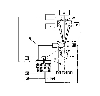
Referring now to Figure 1, a preferred embodiment of the invention can be seen
in
detail. The flow cytometer (20) can utilize a source of stream fluid (24) to
supply stream
fluid to establish a sheath of fluid in which particles (32) can be suspended.
The source of
particles (28) can insert the particles from time to time such that the
particles become
suspended in the stream fluid and are hydrodynamically focused in the stream.
A stream
CA 02320835 2000-08-15
Wu ~Ilm-~U~r ~ m. mu~~~~rumts~
(36) comprised of the stream tiuid (40) and the particles (32) can then be
established below
the nozzle (64) of the tlow cytometer. 'The stream can be established in a
steady state
Colldltl(lll sUCll that droplets (44) are formed and break away from a
contiguous part of the
stream. When the stream is established in this steady state fashion, a stable
break-off point
(48) can be established. This stream can be strobed with a stroboscope to
illuminate the
stable stream. At the break-oft point the stream breaks off into droplets with
these droplets
centered about the break-off point. The droplet break off point is the point
in a stream where
a droplet separates from the contiguous flow of the stream. For reference
puyoses, the center
of the droplet will be considered the droplet break off point when it is
necessary to define the
point in such an exacting manner. Below the droplet hreak-off point (48) a
free fall zone
(52) can exist. 'This free fall zone embodies the area where the droplets move
once they
break away from the contiguous part of the stream. At the bottom of the nozzle
(64) a
stream exit point (56) is established. The exit point is the point in space
where the stream
emerges from the flow cytometer. For example, the exit point on a flow
cytometer having a
nozzle would exist where the stream exits from the nozzle. At this point the
stream
essentially emerges or is ejected from the flow cytometer. A droplet charging
location (60)
can exist at a point along the stream. This droplet charging location (60) can
exist, for
example, at the droplet break-off point (48) as seen in Figure 2. As a
possible alternative,
a charging ring can be used and positioned below the droplet break-off point
such that the
individual droplets can be charged. An oscillator (68) as shown in Figure 1,
can be used to
perturb the stream and to establish a steady state oscillation of the stream.
It is preferred to
use a piezoelectric crystal to accomplish this perturbation of the stream. The
oscillator (68)
may have an adjustable oscillation frequency that can be adjusted to perturb
the stream at
different frequencies such that droplets are created at different rates.
Furthermore, it can
be used in conjunction with the stream pressure to establish the rate of
droplet formation.
A detector (72), such as a laser and receiver in combination, can be used as
seen in
Figure 1 to monitor the stream for a particle. 'The detector can detect the
particle in the
stream as the particle passes through, for exatnple, a coherent beam of light
aimed at the
stream by the detector. When the coherent beam of light intercepts a particle
in the stream,
fluorescence or scattered light rays can then be emitted or deflected,
respectively, as shown
CA 02320835 2000-08-15
WU 'III~I~iUJI ~ 1 v..IiUJJ%luylOJ
in Figure 2 to a receiver of the detector. Alternative methods of detection
are also well
understood by those of ordinary skill in the art.
As the droplets fall in the free tall zone, they can pass through a sorting
force
generator (80) such as electrostatic plates shown in Figure 1. If the droplets
have been
S charged with a positive or negative charge, an electric field estahlished
between these
electrostatic plates will deflect the charged droplets such that the
trajectory of the droplets
is changed. As seen in Figure 1, these droplets can then be deflected into a
container (76)
which acts as a sample collector. Similarly, those droplets that are neutrally
charged can
fall into the center container shown in Figure 1 and droplets that are
alternatively charged
can fall into a third container. Furthermore, alternative techniques such as
utilizing
different quantities of charge can be used to accomplish an even greater
deflection.
'I'o accomplish the charging of the droplets a charging device (84) can be
used to
charge the stream fluid. 'Therefore, when a particle is detected and known to
have reached
the droplet break-off point, the stream can be charged such that when the
droplet breaks
away from the stream, it contains a net charge. A net charge should be
understood to mean
either a net positive, net negative, or even a neutral charge. Then, the
charging device can
be turned off or even configured to produce an opposite charge such that
subsequent
droplets which have been induced with a charge by the droplet containing a
particle are
counteractively charged back to the steady state charge of the stream -
typically a neutral
charge.
A sensor (88) can be used to accomplish many of.the techniques of the present
invention. Initially, the sensor (88) can measure a property of the flow
cytometer based on
a captured image of the tluid stream. One such property that the sensor can
measure is the
speed of the stream at a point along the stream. Two points of particular
interest are the
speed of the stream at the area just below the exit point of the stream from
the nozzle and at
about the droplet break-off position of the stream.
The sensor (88) can be oriented to measure a wavelength (92) of the stream as
shown in Figure 2. Digital imaging routines can operate on the wave shape to
measure the
CA 02320835 2000-08-15
W O 99/44U37 ~ ~ 1'C:'t /1J599/U4183
length of a standing wave, for example. Furthermore, the sensor can be
oriented to
measure a distance between droplets of the stream such that the distance and
the oscillation
frequency of the oscillator can be utilized to calculate the speed of the
droplets at that point
along the stream. The sensor (88) can utilize a camera (102) with a wide angle
lens that
captures a large portion of the stream or multiple cameras such as those seen
in Figure 2
where a camera (96) captures an image of the stream at an exit point of the
stream and
camera (98) captures an image at the droplet break-off point of the stream. In
this fashion,
camera (96) and camera (98) can serve as a first sensor and second sensor,
respectively, for
determining speeds at different points along the stream. 'The camera (102) as
shown in
Figure 1, can capture an image ( 106) of the stream and display it on a
monitor ( 114).
The camera ( 102) can be oriented to capture various features of the stream.
For
example, the camera can be oriented to capture the width ( I 10) of the stream
as shown in
Figure 3. Alternatively or additionally, the camera can be oriented to capture
an image that
permits determination of a speed of the stream. As discussed earlier, this may
be
accomplished by measuring the wavelength of the stream or measuring a distance
between
two droplets and utilizing the known oscillation frequency to calculate a
speed for the
stream at those two points. Namely, the product of the oscillation frequency
and the
distance between droplets (or the stream wavelength) would yield a stream
velocity at that
point.
1n addition, the camera or sensor may be oriented to capture an image that
permits
determination of a change in stream position. 'This can be done by monitoring
a first
position of the stream, recording that position, and then monitoring the
stream over time to
see if the stream moves away from that previously determined position. The
camera can
capture an image of the stream at the break-off point as well as the stream
exit point where
the stream emerges from the cytometer. Essentially, the camera can be oriented
in many
different orientations to capture many views in order to determine information
ahout the
stream which consequently allows the sensor to determine information about the
characteristics of the cytometer. The various cameras can be used to capture
the image of
the stream, however it is preferred to use a camera that creates a digital
representation for
the image of the stream and one such camera being one that uses a charge
coupled device or
CA 02320835 2000-08-15
WU 9NLtdU37 ~ ~ m. muarmumn~
CCD. A CCD can produce an output in a series of analog voltage pulses each of
which
corresponds to a light intensity received by a pixel of the CCD.
Once the sensor (88) captures an image of the stream, the image can be
displayed on
a monitor ( 114). 'The monitor can then display the image of the stream to a
user.
'l'ypically, a monitor (114) will also be comprised of individual pixel
elements (118) that
correlate to a digital embodiment of the image derived from the CCD. The CCD's
pixel
elements, as well as the monitor's embodiment) can be correlated with a
physical distance
to arrive at an accurate determination of an actual dimension of the stream.
The monitor
( 114) can be positioned at the flow cytometer, or when it is desired to
monitor the flow
cytometer at a remote position, the monitor (114) can be positioned at such a
remote
position.
A memory device ( 122) can be used to store at least one parameter for the
flow
cytometer. Once an image is captured by the camera (102), the memory device
can also
serve to store a representation of the stream, more particularly, a digital
representation of
the stream. An imaging means (126) can be used by the sensor for creating a
digital
representation of the stream. More particularly, a means for outlining (130)
can be utilized
to create an outline of the stream (134) as shown in the representation of the
stream in
Figure 3. Similarly, this means for outlining (130) can be used to create an
outline of an
individual droplet (138). Digital representation is intended to mean a
representation of the
object. For purposes of this patent it will still be considered a
representation when only a
portion or an outline of the border is used rather than the entire object. The
means for
outlining can be comprised of a typical digital imaging processing program or
digital video
processor which can operate on an image to detect actual signal versus noise
in the signal.
Such digital imaging processing programs can be seen by reference to:
Digitalital lmauinu
Yrocessin~ by Kenneth R. Castleman, Prentice Hall Dec. 1, 1995; T'he lmaee
Processing
Handbook, by John C. Russ, CRC Pr. Jan., 1995; Digital Image Processing, by
Rafael C.
Gonzalez, Addison-Wesley April I, 1992; and Algorithms for Image Processing,
by
James R. Parker, John Wiley & Sons Nov. 1, 1996 which are hereby incorporated
by
reference. Furthermore, U.S. Patent 5,700,692 discusses imaging techniques and
is hereby
incorporated by reference for the imaging techniques disclosed.
CA 02320835 2000-08-15
W ll J'I/'iJllJ I ~ 1'l. 1 I UJ'JJ/ll-I1 tt.i
An analyzer ( 142) can be used co analyze an image of the stream in order to
determine information shout the flow cytometer. For example, the analyzer can
determine
a distance between ohjects, I~urthermore, the analyzer can determine a
deflection of a
charged droplet from the central axis of the stream based on the droplet
position in the
image and the uncharged stream steady state position. 'This can be
accomplished by simply
measuring the distance of the droplet from the steady state stream with a
typical digital
imaging processing program.
The analyser ( 142) can also determine a charge on the droplet. For example,
when
one wants to know whether the proper charge was applied to a droplet the
analyzer can he
used to determine the actual charge as compared to the anticipated charge on
the droplet.
'This can be accomplished by noting the deflection of the charged droplet from
the stream
noting the droplet size based on the image, measuring the mass of the droplet,
which is a
function of the droplet size and mass of the known tluid, and the known
electric field set up
by the deflection plates. In this fashion, the actual deflection can be used
to deduce the
1 S charge on the droplet and therefore that actual charge can then be
compared to the
anticipated charge to confirm whether the charging procedure is actually
charging the
droplets to the proper charge. In addition, a droplet sizes can be detected at
the breakoff
point and the charging point adjusted to charge the droplets such that they
will be deflected
the appropriate distance given their size.
The analyzer can also be used to calculate the best "defanning" charge based
on the
deflection (or charge) of a previous droplet. For example, when one wants to
establish a
very steady stream of uncharged droplets, i.e., avoid a stream of uncharged
droplets that
make the stream appear like it is fanning back and forth, it is often
necessary to apply a
partial charge to droplets neighboring charged droplets. This is due to the
fact that the
charged droplets will induce a charge on neighboring droplets. Therefore, by
slightly
charging droplets that occur after a charged droplet, the induced charge on
the successive
droplets caused by the charged droplets can be counteracted. For example, if a
positively
charged droplet is expected to induce a negative charge on a successive
droplet, the
successive droplet can be charged slightly positive to counteract the induced
effect.
CA 02320835 2000-08-15
w() ~l ~la~tus l ~ 3 m. m uJWU-~ i ris
The analyzer can also be used to measure the width of a stream which allows a
determination of nozzle size. For example, the stream width of 60 microns (or
25 pixels on
a 48U x 512 pixel image) can he determined to indicate a nozzle size of 70
microns.
Furthermore, the analyzer can be used to determine the best resonant frequency
for the
cytometer. For example, the image can be analyzed to see where the stream
establishes the
shortest break-off point and the oscillation frequency of the oscillator can
be set to
correspond to that point. 'Typically, this will be a function of nozzle size
and velocity.
Furthermore, the analyzer can he used to determine the speed of the stream
based on
distances determined in the image and the known frequency of the oscillator.
1'0
accomplish this analyzation process, the analyzer ( 142) can utilize a
computer ( 146). 'Che
computer ( 146) can utilize the approximate speed of the stream at a first
position and the
approximate speed of the stream at a second position along the stream in order
to determine
a stream characteristic by modeling the speed of the stream in a region
occurring between
the stream exit point and the droplet break-off point as decaying
approximately
exponentially relative to distance.
Furthermore, the analyzer can utilize a means for determining a change in
droplet
break-off position ( 150) to determine when the break-off position of the
stream changes.
'This can be accomplished by recording a droplet break-off position and
comparing that
position to subsequent break-off positions noted in subsequent images. A
simple computer
program can be used to accomplish the means for determining a change in
droplet breakoff
position, by storing a representation of the droplet breakoff position,
capturing a second
digital representation and then comparing the two representations to see if
they correspond.
The analyzer can also use a means for determining drop delay ( 154), the drop
delay
being associated with a detected particle. A drop delay (or drop delay time)
is considered to
be the delay in time between detecting a particle in the stream and acting
upon the droplet in
which the particle is contained in order to accomplish a sort of the particle.
For example, in a
typical flow cytometer, a particle will be detected by a detector and
characteristics of the
particle will be determined based on a fluorescence of light from the
particle. Then, based on
the characteristic, the droplet the particle is in will be charged just before
it breaks away from
CA 02320835 2000-08-15
W IWJ~JIJ~IU.S I ' ~ . ~. w. J %'lm. m UJ
the stream and sorted by an electrostatic sorter. The drop delay in this
instance can be
considered to be the time between detection of the particle and charging of
the droplet. In
another embodiment, one miglO choose to charge all the droplets, but only
apply the
electrostatic field for the panicle/droplel to be sorted. In this case, the
drop delay would he
the time between the detection of the particle and the act of applying the
electrostatic field.
Similarly, the drop delay might be initiated at a point in time after the
first defection of the
panicle, such as the time when the particle fluoresces. In this case, the drop
delay migtU be
ealculatecl as the time between detection of a florescence and the time for
the particle to reach
the charging location. Similarly, for embodiments that use a charging ring to
charge a droplet
separate from the stream, the drop delay might be calculated from the point of
panicle
defection to the point where charging occurs. Determination of the drop delay
time can be
accomplished with a simple software program for instance by determining a
speed of the
fluid stream at a particular position and modeling the speed of the stream
based on an
exponentially decaying speed with respect to distance. Therefore, the software
routine
could account for the change in speed of the stream over a distance and derive
a time for
the particle to traverse that distance to arrive at the charging location. For
example, a
comparator ( 158) can be used to compare determined information about the
stream, for
example, a measured property of the flow cytometer to a parameter of the flow
cytometer.
F~or purposes of this application, a parameter is a pre-determined or expected
value for a
characteristic of a thing, such as an expected width of a stream in a flow
cytometer, an
expected nozzle size, an expected break off position, an expected stream
location, etc. On the
other hand, and again for purposes of this application, a "property" is a
duality, trait or
quantitative value representative of a thing, such as the measured width of
the flow cylometer
stream, the measured pressure of the stream, the measured distance from a
nozzle tip to the
droplet break off point, the measured temperature of the stream, the actual
mass of the fluid
used for the stream, etc. 'rhc means for determining drop delay can utilize a
compensator
(162) to compensate for change in speed of the stream after the stream emerges
at the exit
point of the flow cytometer. Cssentially this compensator can be comprised of
a software
routine that models the speed of the fluid as exponentially decaying, as those
who are
skilled in the art would easily understand.
A time delay generator ( 164) can be utilized by the flow cytometer (20) to
provide a
delay in charging the droplet which contains the detected particle once the
particle is
CA 02320835 2000-08-15
W() 99/JJU37 ~ S rW : 1 iU~'IHJUa I2i5
detected in the stream. Based on the results from an analyzer, the time delay
generator can
be set and used to control the droplet charger (84). A signal generator (168)
can he used by
the analyzer to generate a signal to the flow cytometer or to external
indicators based on tl~e
determined inforrnation from the stream. Por example, the signal generator can
generate a
signal used to re-establish the droplet break-oft position. Furthermore, the
signal generator
can issue an error warning about the flow cytometer based on the determined
information
from the stream. In addition, the signal generator can be used to generate a
signal to the
flow cytometer based on the comparison of the first digital representation of
the stream and
a second digital representation of the stream as explained above.
Figure 1 shows a remote paging device (172) that can be located with an
operator of
the flow cytometer when the operator leaves the area where the flow cytometer
is located.
Given the advancements of the present invention which allow the flow eytometer
to detect
catastrophic events, it is possible for an operator to leave the llow
cytometer unattended
and to perform activities elsewhere. The remote paging device can be used to
warn the
IS operator, for example, that a catastrophic event, i.e., an event which
requires a cessation of
sorting such as total loss of the stream, clogged tubes or nozzle, or air in
the cytometer
chamber, has occurred so that the operator can return to the flow cytometer
and attend to
whatever problem may exist. A remote computer monitor (176) can also be
utilized with
the flow cytometer to provide a similar warning. For example, the flow
cytometer could be
connected on a Windows N'1' platform such that a pop-up message can be
displayed on an
operator's terminal indicating the completion of a sort or a problem with the
flow
cytometer. Similarly, the flow cytometer can be connected to an E-mail system
such that
an E-mail message can be automatically routed to a user.or interested party.
Alarm circuitry (18U) can be utilized to indicate an alarm condition. Such
circuitry
may be comprised of an alarm ( 184) which can assume a variety of
configurations such as a
displayed message, a flashing light, a buzzer, or other commonly used devices.
One novel feature of a present embodiment of the invention is the use of a
mechanical interrupter ( 188) which can be utilized to intercept andlor
interrupt the stream.
For example, the mechanical interrupter ( 188) may be utilized after the
stream exits from
CA 02320835 2000-08-15
W(~'lNl.~4ll.i7 ~ ~ 1'l: I IUJ'IJ/UJ ltf.i
the exit point of the tlow cytometer such that the stream can be interrupted
and diverted
away or deflected away from its normal course or from the abnormal course that
is caused
due to a problem with the flow cytometer. The mechanical interrupter can be
used to
interrupt the stream based on a determination made by the sensor. In this
fashion it can
work automatically. One possible embodiment of the mechanical interrupter can
utilize a
gutter ( 192) as shown in t~igure 4 which ruutes the stream away to a waste
container after
the gutter swings in to intercept the stream. Alternatively, a deflector (196)
can be used to
swing into position such that the stream is deflected away to the waste
container.
Preferably these mechanical interrupters are located close to the exit point
of the stream
such that the stream can he diverted as early as possible to avoid
contamination of the
collected samples. Both may swing or slide in either manually or
automatically.
With a background understanding of the apparatus of the present invention, the
method of utilizing the apparatus to accomplish various embodiments of the
invention can
now he better understood. In particular, one aspect of the present invention
involves
1 S utilizing an imaging system to capture images of the stream. Particularly
the droplet break-
off poini of the stream can he captured as an image such that a speed of the
stream can be
determined. 'This can be accomplished by imaging the stream and identifying
droplets that
form below the droplet break-off point and determining a distance using
imaging techniques
between subsequent droplets. These droplets will be traveling at a speed very
close to the
droplet that is located at the droplet hreak-off point. The image of the
stream can be stored
as a digital image in memory, e.g., RAM, of the cytometer.
Imaging techniques can be utilized to analyze the stream. For example,
electrical
noise can be eliminated from a captured image. This may involve capturing a
first image of
the stream at a location along the stream and creating a first digital
representation of the
stream based on the first image. For example, an outline of the stream might
be created.
Then that digital representation of the stream can be stored in memory. For
example, the
outline can be stored in memory. Additionally, an outline of a droplet from
the stream can
be created and stored in memory as well. Next, a second image of the stream at
the same
location can be captured and a second digital representation created. The
second digital.
representation of the stream can be based on the second captured image. Then,
the two
CA 02320835 2000-08-15
wu mm.~u~ ~ 1 ~ l 1. 1 l UJYIIll~l1 bJ
digital representations of the stream can be compared and a determination can
be made
whether a property of the stream has changed based on the comparison of the
first digital
representation with the second digital representation. Standard digital signal
processing
techniques can be used to accomplish this as would be understood by those of
ordinary skill
in the arts.
Purihermore, one embodiment of the invention can determine information about
the
flow cytometer based on a captured image. For example, this might be
accomplished by
measuring a property of the tlow cytomeler based on the captured image. Such
properties
might include; the width of the stream, the speed of the stream, the pressure
of the fluid, the
l0 wavelength of a wave on the stream indicative of the stream speed, or other
characteristics.
Furthermore, information can be determined about the tlow cytometer by
associating a
physical distance with a digital image block or a pixel dimension. An actual
physical
distance can be determined based on the number of blocks or pixels used to
represent that
distance on the captured image.
The captured image can also he used to determine a velocity of the stream.
This can
be accomplished by measuring a wavelength of the stream at some position along
the
strewn. Furthermore, the oscillation frequency of the oscillator can be used
in conjunction
with the measured wavelength to calculate an approximate speed of the stream.
A velocity
of the stream can be determined at an approximate exit point where the stream
emerges
from the flow cytomeler by measuring a wave length there and utilizing the
known
oscillator frequency. In addition, an approximate velocity of the stream can
be measured at
about the droplet break-off point by imaging droplets and measuring the
distance between
successive droplets. By utilizing the oscillation frequency to determine the
time period
between successive droplets and given the measured distance an approximate
velocity can
he calculated for the droplet break-off point.
The captured image can also be utilized to determine a drop delay time for a
particle
in the stream. This can be accomplished by determining an approximate first
speed of the
stream at a location along the stream and then determining an approximate
second speed of
the stream at a different point along the stream. Preferably a speed close to
the particle
CA 02320835 2000-08-15
wum«.+um t~ u~~~u~muain~
detection point would he utilized tbr the first speed of the stream and a
measurement of the
stream speed at approximately the droplet break-off point would be utilized
for the second
speed of the stream. These two speeds can then be used as part of a model for
purposes of
modeling the stream speed. Cxperimenlal results indicate that the speed of the
stream will
S approximately exponentially decay from the point where it is ejected from
the flow
cytometer to a typical droplet break-off point. However, an appropriate
function of the
speed could easily be determined for a stream by generating calibration data
for stream
once the stream was established and deriving a real function for the change in
speed of that
stream for the actual conditions. A typical velocity of the stream at the exit
point will
typically, in one embodiment of the invention, approach 27 meters per second,
while at the
break-off point the velocity will have dropped to 25 meters per second. Thls
Is believed to
he due to hydrodynamic relaxation of the stream over the distance from the
exit point to the
droplet break-off point. In previous attempts by others to determine an
appropriate drop
delay time those earlier attempts had utilized a constant velocity throughout
this range of
the stream. Therefore, this probably resulted in a less accurate drop delay
time and
consequently a poorer result in charging a desired droplet. Consequently, once
the first
speed of the stream and the second speed of the stream are measured, the
stream speed can
he modeled as decaying approximately exponentially - as experimental data
suggest - in the
region between the exit point and the droplet break-off point. Then, given the
point where
a particle is detected and a known distance to a charging point for the
droplet containing the
particle (or even by determining that distance through imaging of the stream
by determining
the present droplet break-off point when the particle was detected or
monitoring a shift in
that droplet break-off point as the particle descends in the stream), the flow
cytometer can
compensate for the change in speed due to the exponential decay of the speed
of the stream
in the region. Then based on this modeling of the stream speed and the
compensation for
the change in speed the flow cytometer can determine a time for the particle
to flow over
the distance to the charging point. In this fashion, the approximate speed of
the stream at
the first position along the stream and the approximate speed of the stream at
the second
position along the stream can be used to determine the stream characteristic,
namely in this
example, a drop delay time for the stream.
CA 02320835 2000-08-15
a ~~~)~.i.,US ~ 1 ~~ a \, 1 i a J % %! V v 1 UJ
Once a drop delay time has been calculated that drop delay time can be
utilized to
calculate when the particle will reach a droplet charging location, e.g.,
based on the known
point in time when the particle was detected. Then, the tlow cyiometer can
charge the
droplet containing the particle as it reaches the charging location, for
example, by charging
S the stream or by using a charging ring.
As noted earlier, a present embodiment of the invention can be used to measure
properties about the flow cytometer in order the generate warnings about the
flow
cytometer. 'This can involve defining at least one parameter for the flow
cytometer and
comparing that parameter to a measured property or characteristic of the flow
cytometer.
In view of this comparison the flow cytometer can then determine when the
operation of the
flow cytometer does not satisfy at least one parameter defined for the flow
cytometer.
For example, a warning can be generated after determining that a change in
position
of the droplet break-off point has occurred. In previous setups, others have
relied on a
technician to constantly watch an image of the stream to see if the droplet
break-off point
I S shifts in position. Wiih the present imaging techniques that allow
comparison of previous
droplet break-oft points with successive droplet break-off points, this
procedure can be
automated such that a warning signal is generated to an operator of the flow
cytometer.
As another example, the flow cytometer allows for adjusting a drop delay time
so as
to properly charge a droplet at the droplet break-off point. 'This can involve
detecting the
speed of the stream and the current known droplet break-off point at the point
in time when
the particle is detected, and then calculating the drop delay time for that
particular particle
or even adjusting that drop delay time again as a droplet break-off point
change is sensed
after particle detection.
Furthermore, a present embodiment of the invention is to constantly monitor
and re-
establish the position of the droplet break-off point (or fiducial break-off
point) (48) from
the stream. The instant invention allows the determination of the position of
the droplet
break-off point to be ascertained relative to the fixed point of detection of
the particle in the
stream by the particle detection system or detector, or laser and receiver
(72). This
CA 02320835 2000-08-15
WU 9Nl.t4U.i7 ~() tW, r I UJH'Jill.t rti5
assessment of the position may be accomplished by taking sequential high
resolution scans
or images with a camera or monitor (102) synchronized with the strobe phase
and the
droplet charging phase (84) so as to record an image of sequential droplets as
they reach tire
break-off point from the stream. 'fhe images of the droplets at the location
of break-off is
digitized(126) and held in a memory device (122). Digitized data relating to
the location of
the droplet break-off points is then compared electronically. The distance
hetween droplet
break-off points may be determined by the digital image processing program.
Then, as the
droplet break-off point hegins to shift in either direction, a feedback signal
may be
generated to either increase or decrease the amplitude of the oscillations
from the oscillator
(68) in order to re-establish the droplet break-off' point in its previous
position. 'fhe
position of the droplet break-off point may be re-established in this manner
because the
distance at which droplet hreak-off occurs from a stream is a function of the
stream velocity
(Vh), the disturbance amplitude, and a time constant which is a function of
surface tension,
fluid density, jet diameter (d~)~ and wavelength. The disturbance amplitude
(Va) is
IS proportional to the oscillator voltage to the oscillator (68) through a
coupling constant (Cc).
Therefore, droplet break-off distance (Xb) which varies relative to a fixed
position due to
fluctuation in stream velocity, may be held constant by varying the
disturbance amplitude
while wavelength, fluid density, surface tension and jet diameter are held
constant. These
relationships are summed up in the following equation:
Xb= Vb.Te(Vb,d)-Vb.log(Cc. Va)/y
where Te is a delay correction due to the non-uniform velocity profile of the
stream where
Te= klVb = 332.0/Vb, and
y is defined by a Rayleigh analysis where
y=~ (8.o/(p.d (~.(1-~)Iy~)/Iu( ) , and where
~=~.d~.f/Vb, as such using standard Rayleigh parameters.
'These functional relationships are used in conjunction with computer software
and
computer hardware to create a oscillation control device which generates a
signal which
adjusts the voltage to the oscillator which varies the oscillations to the
stream in response to
the variation in location of the fiducial break-off point. The variation of
oscillation to the
CA 02320835 2000-08-15
W() 9N/4dU37 2 ~ Yl.' I IU'HHl0.llti.5
stream thereby maintains the location of the fiducial break-off point. Failure
to maintain
the fiducial break-off point may lead to a computer controlled automatic
suspension of
sorting activity.
In another embodiment of the invention an alarm or warning based on the
information in or determined from the captured image can be generated. Such an
alarm or
warning can be based on a comparison of the determined information about the
flow
cytometer with an expected characteristic of the flow cytometer. This might
involve
issuing an error warning about the flow cytometer based on a comparison of the
determined
information and the expected characteristic.
'The types of warnings that can be issued by the flow cytometer can be seen
through
the following examples. For example, it might be desirable to compare an
expected stream
width, such as stream width ( 110) shown in Figure 3 with a predetermined
stream width
expected for use in a particular set-up or for a particular particle to be
sorted. In this
fashion if an expected stream width is expected and a different stream width
is measured, a
warning can be generated to the user or operator indicating that an incorrect
nozzle size
may be connected to the t7ow cytometer. Similarly, the error warning might
indicate that
an improper pressure is being used. In addition, as noted earlier, the imaging
technique
can be utilized to determine a speed of the stream and this determination of
the stream
speed might be utilized to issue a warning about the pressure of the stream.
If an expected
stream pressure would create a predetermined stream speed and a measured
stream speed
were different from that predetermined stream speed, then an error warning
might be
appropriate. One significant aspect of the present invention is its ability to
react to a
catastrophic failure of the cytometer. This might be most noticeable through a
significant
change in position of the stream due to clogging of the nozzle. The imaging of
the stream
would allow a steady state position of the stream to be recorded and compared
to
subsequent images of the stream. When a clogged nozzle, for example, diverts
the stream
at an angle, the imaging technique of comparing subsequent images to a steady
state image
would allow the flow cytometer to determine that a catastrophic event was
occurring and
issue a warning to the user or even automatically interrupt the sorting
process in order to
perfect the previously sorted sample. The warning can be generated in a
variety of ways.
CA 02320835 2000-08-15
Wll 'JH/~i~UJ~! 22 1'l.I/llJ%IIU~ItSJ
One such way might be through displaying a warning on a remote computer
monitor where
an operator is working. Furthermore, a warning might be issued to a paging
device.
Another significant embodiment of the invention allows the flow cytometer to
disable the source based on information determined from a captured image. For
example,
given the catastrophic failure detected earlier due to a diversion of the
stream or even the
complete loss of stream, the flow cytometer can act by mechanically
interrupting the sort.
This can be accomplished by automatically moving, swinging, or sliding a
gutter as shown
in Figure 4 so as to intercept the stream and then channeling away the stream
in the gutter
to a waste receptacle. Alternatively, this mechanical interruption might be
caused by
automatically moving, sliding, or swinging a deflector, for example, a plate,
in order to
deflect the stream away from the collected sample that was already produced by
the flow
cytometer. Alternatively, or perhaps even in addition to, where the stream is
still present,
the flow cytometer can automatically act to turn off the charging device or
the deflection
source such that the charged particles are not deflected into the collected
sample.
1 S Finally, one embodiment of the invention can be utilized to automatically
issue an
alarm signal. In this fashion an operator can be notified that the flow
cytometer has an
alarm condition, for example, any abnormal condition. Such alarm signals might
utilize
either an audible or visual alarm.
'fhe foregoing discussion and the claims that follow describe the preferred
embodiments of the present invention. Particularly with respect to the claims
it should be
understood that changes may be made without departing from the essence of the
invention. In
this regard, it is intended that such changes would still fall within the
scope of the present
invention. It is simply not practical to describe and claim all possible
revisions which may be
accomplished. To the extent such revisions utilize the essence of the present
invention, each
naturally falls within the breadth of protection encompassed by this patent.
Further, it should
be understood that various permutations and combinations of the elements shown
in the
claims are possible and should fall within the scope of this disclosure. In
addition, it should
be understood that the use of the word "comprising" is intended to have an
inclusive meaning
rather than an exclusive meaning. Therefore, in foreign countries, such as
Australia, where
CA 02320835 2000-08-15
WU H'J/J~U3 / '3 t'm I J U ~Il/ll~ tbJ
this application may be relied upon as a priority document, the meaning of the
word
"comprising" is intended to have an inclusive meaning.
The discussion included in this application is intended to serve as a basic
description.
The reader should be aware that the specific discussion may not explicitly
describe all
S embodiments possible; many alternatives are implicit. T'he market place and
manufacturing
concerns may dictate tile appropriate embodiments for the present invention.
Particularly
with respect to the discussion, it should be understood that a number of
changes may be made
without departing from the essence of the present invention. In this regard,
it is intended that
such changes - to the extent that they substantially achieve the same results
in suhstantially
the same way -- will still fall within the scope of the present invention. It
also may not fully
explain the generic nature of the invention and may not explicitly show how
each feature or
element can actually be representative of a broader function or of a great
variety of altemativc
or equivalent elements. Again, these are implicitly included in this
disclosure. Where the
invention is described in apparatus-oriented terminology, each element of the
apparatus
implicitly performs a fimction. Apparatus discussions or claims may not only
be included for
the systems described, but also method or process claims may be included to
address the
functions the invention and each element performs. As but one example of this
aspect, the
disclosure of a "sensor" should be understood to encompass disclosure of the
act of "sensing"
-- whether explicitly discussed or not -- and, conversely, were there only
disclosure of the act
of "sensing", such a disclosure should be understood to encompass disclosure
of a "sensor."
Although the methods related to the system are being included in various
detail, only an
initial discussion directed toward the biosensor has been included. Naturally,
that discussion
could have some application to the various other methods and aspects discussed
throughout
the disclosure. Neither the description nor the terminology is intended to
limit the scope of
the claims which will be included in a full patent application.