Note: Descriptions are shown in the official language in which they were submitted.
CA 02321064 2000-08-15
WO 99/41488 PCT/US99/03322
1
SURFACE-ASSISTED CONTINUOUS UNDERGROUND MINING
BACKGROUND OF THE INVENTION
Field of the Invention
This invention pertains in general to the field of
underground mining and, in particular, to a novel
adaptation of continuous-miner development and retreat
mining techniques for shortwall and longwall to recover
underground reserves under shallow cover.
Descrit~tion of the Relat ~ Art
Continuous underground mining is used to extract fossil
fuels and other valuable minerals found in strata-bound
deposits. Historically, underground mining is carried out
by gaining access to the ore through entries developed
from an exposed seam. This development is generally done
from the point of interest at the surface, such as at an
outcrop or from an exposed highwall resulting from surface
mining. All mining utilities, ventilation, transportation
of personnel, and removal of the mined material are
carried in and out by utilizing such entries within the
mineral seam. As a result, it has been conventional
practice not to exploit with underground methods deposits
having shallow cover with no highwalls or outcrop, or ones
with reclaimed highwalls having spoils placed against
them, or with highwalls or an outcrop left unsuitable for
entry because of previous mining. It has been found that
gaining underground entry to the seam through such
unfavorable conditions would render the practice
uneconomical under most circumstances. On the other hand,
gaining entry to the seam through a vertical or inclined
shaft results in significant cost increases that often
also render the operation uneconomical. The expense of
lowering belt and structure components, as well as
CA 02321064 2000-08-15
WO 99/41488 PCT/US99/03322
2
electrical, hydraulic and pneumatic system parts, through
the shaft and assembling them underground would be
prohibitive. Therefore, there is a need for an efficient,
economic and safe method of recovery of underground coal
reserves under such conditions.
This invention is directed at providing an affordable
approach to the exploitation of such shallow reserves by
combining efficient seam-mining practices, such as the use
of continuous miners, shortwall and longwall, with access
to the reserve by means of a vertical shaft equipped with
a novel continuous system for feeding infrastructure to
the mining face. Thus, the invention materially enhances
the feasibility of mining shallow reserves with no direct
access to the seam.
The invention is described in the context of coal mining,
but its principles are equivalently applicable to any
material suitable far extraction with continuous mining
equipment, such as lignite, oil shale, limestone,
anthracite, trona, potash, halite, bauxite, gypsum, and
other sedimentary rocks that host oxide, sulfide or
carbonaceous gold ores and/or other poly-metallic
minerals. Similarly, the invention is described in terms
of a mine developed through a shaft, but it is
equivalently applicable to mines where access to the
reserves is obtained through entries within the ore seam.
BRIEF SUMMARY OF THE INVENTION
The primary goal of this invention is a method of mining
underground coal that does not require the conventional
in-seam support infrastructure of underground operations.
Another important objective is a system of support
infrastructure that can be at least partially assembled on
CA 02321064 2000-08-15
WO 99/41488 PCT/US99/03322
3
the surface and fed continuously underground, thereby
minimizing the piecemeal progress and corresponding shut-
downs that are typical of underground mining.
Another objective is a method of providing mine support
infrastructure from the surface that encompasses all
utility systems necessary to a continuous mining
operation, including belt and belt structure, hydraulic
lines, pneumatic hoses, electric cables and communication
cables.
Another goal is a method of providing infrastructure that
is compatible for use with continuous underground-mining
equipment, such as continuous miners, shortwall and
longwall.
Yet another objective is a method of mining that is
particularly suitable for the economic recovery of coal
reserves left under shallow cover behind an inaccessible
highwall or outcrop.
Finally, an objective of the invention is a mining
technique that is compatible with and suitable for direct
implementation with prior-art mining methods and
equipment.
Therefore, according to these and other objectives, the
present invention consists of sinking a vertical shaft to
reach a coal reserve through a shallow cover and using the
shaft for providing utilities and support infrastructure
virtually on a continuous basis directly from the surface
to the mining face of the underground operation. A
flexible belt structure system incorporates water supply
and discharge lines, power and communication cables,
hydraulic supply and return lines, bulk lubrication
delivery systems, and belt support structure for
underground coal haulage. The system consists of modular
CA 02321064 2000-08-15
WO 99/41488 PCT/US99/03322
4
components that are added at the surface and connected
underground to form a continuous support structure to the
working area, such that the infrastructure necessary for
the mining operation is expanded or reduced to keep up
with the position of the mining face without interruption
of operation. The belt structure is mounted on stationary
rail or cable fixed to the roof of the mine and is rolled
forward or backwards in the belt entry as the mine
advances or retreats, as applicable.
According to one aspect of the invention, the flexible
structure system is fed through the mine shaft and is
attached to a monorail or a cable guide hung horizontally
in the seam entry to the face. The rail is bolted to the
roof as part of the normal roof control plan as the mining
face advances, thereby extending the reach of the belt and
allowing it to keep up with the advance of the continuous
miner. On retreat, unused rail segments can be removed
or, preferably, left attached to the roof bolts behind the
retreating face. The belt structure is mounted on rollers
hung from the rail, so that the belt's tail loading end or
"tail piece," which is part of a mobile boot end, remains
with the continuous miner tail or the discharge of the
stage loader conveyor from a longwall as it moves in
advance or retreat. Each module of the structure is
articulated to permit bending as necessary to reach the
mining face.
According to another aspect of the invention, the belting
is routed to a belt drive on the surface of the mine
through a vertical shaft. This shaft is used to provide a
gravity belt storage unit that affords exceptional storage
capacity. The belt is laced around the conveyor drive
unit at the top of the shaft. This permits the slack side
of the belt to be looped and weighted along the length of
the shaft, providing a large vertical gravity storage unit
that eliminates the need for the more limited horizontal
CA 02321064 2000-08-15
WO 99/41488 PCT/US99/03322
belt storage units used in traditional underground mining
operations. As a result of this method of belt storage
and its capacity, the belt can be advanced continuously
for distances heretofore unattainable before a shut-down
5 is required for splicing. Because the belt storage unit
hangs vertically in the shaft, the belt is appropriately
and simply counter-weighted for proper tension.
Another aspect of the invention relates to the placement
of the belt drive on the surface. This location permits
direct access to the belting on the surface for splicing
additions and removals. Surface splicing is facilitated
with surface handling equipment and does not require
underground transport of large rolls of belting. Belt
addition and removal are made during shut-down periods
scheduled for such purposes, which are shorter than they
would be underground.
The placement of the belt drive on the surface also
affords environmental advantages. Since the belt on the
surface is away from the transfer point of coal or ore,
the amount of dust in the atmosphere and accumulated on
the ground in the immediate area is less than it would be
underground. In the case of coal, the resulting fresh
atmosphere at the surface makes it possible to use motors
without the safe rating required for underground
applications. In addition, the cleaner air environment
makes it possible to utilize more reliable vulcanized-
rubber splices rather than the more common mechanical
splices that are required in typically dirty underground
environments.
According to still another aspect of the invention, pipes,
cables and hoses that are normally attached to the roof or
to the belt structure underground and are advanced by
shutting each system down and adding lengths of hardware,
are instead fed to the mine continuously from the surface
CA 02321064 2000-08-15
WO 99/41488 PCT/US99/03322
6
where each system is stored in large quantity in a
separate unit capable of continuous delivery. Each pipe,
cable and hose is laced through each modular segment of
the flexible belt structure in continuous fashion from the
surface. These systems are advanced or retreated, as
applicable, with the rest of the structure, so that all
utilities are available all the way to the mining face
without interruption during advance and retreat phases of
mining.
Each module is completely and incorporated into the
infrastructure system near the transfer point of the
underground belt from the face. The modules, which
include top and bottom belt rollers, are added to the
system as the mining face advances (or removed as it
retreats, as applicable). As each module becomes aligned
with the centerline of the belt conveyor already in place,
it is installed such that its rollers engage the moving
belts in the system and the module becomes integrated with
the belt support structure already in place.
Various other purposes and advantages of the invention
will become clear from its description in the
specification that follows. Therefore, to the
accomplishment of the objectives described above, this
invention consists of the features hereinafter illustrated
in the drawings and fully described in the detailed
description of the preferred embodiment and particularly
pointed out in the claims. However, such drawings and
description disclose but some of the various ways in which
the invention may be practiced.
BRIEF DESCRIPTION OF THE DRAWINGS
Fig. 1 is a schematic cross-section of an underground coal
mine wherein the seam is accessed through a vertical shaft
CA 02321064 2000-08-15
WO 99/41488 PCT/US99/03322
7
according to the present invention and then developed by
traditional continuous mining techniques.
Fig. lA is a schematic top view of an underground coal
mine plan suitable for the invention, showing the location
of the entries and cross-cuts of a 2-entry development
system with continuous miners in each entry.
Fig. 2 is an enlarged view showing the shaft portion of
the mine illustrated in Fig. 1.
Fig. 2A is a further enlarged view of the transfer point
of the underground belt showing the assembly of the
structure of the invention.
Fig. 3 is an enlarged view showing the mining face portion
of the mine illustrated in Fig. 1.
Fig. 4 is an elevational front view of a belt-structure
module according to the invention.
Fig. 5 is an elevational side view of the belt-structure
module of Fig. 4.
Fig. 6 is a top view of the belt-structure module of Fig.
4.
Fig. 7 is a top plan view of the surface facilities of a
mine developed with the infrastructure system of the
invention.
DESCRIPTION OF THE PREFERRED EMBODIMENTS OF THE INVENTION
The heart of this invention lies in the development of a
modular belt structure and the idea of combining all
utility delivery systems for an underground mine in a
CA 02321064 2000-08-15
WO 99/41488 PCT/US99/03322
8
single movable infrastructure system capable of being
integrated with the advance and retreat of continuous
mining equipment. For the purposes of this invention,
continuous mining equipment is defined to encompass not
only conventional continuous miners, but also longwall and
shortwall cutting machines and any other equipment capable
of continuous production in conjunction with a conveyor
belt reaching the vicinity of the cutting face. A
vertical shaft and conventional seam-entry development for
coal access and removal by continuous miner are used for
illustration, but the concepts of the invention are
applicable to any type of in-seam continuous mining.
As illustrated schematically in the cross-sectional view
of a mine of Fig. 1, the preferred implementation of the
system of the invention is achieved by sinking a vertical
shaft 10 from the surface 12 to the coal seam 14, where an
underground mine entry 16 is developed with conventional
mining equipment. An appropriate longwall-panel
development and ventilation plan consistent with the
invention is illustrated in Fig. lA, but is not discussed
in detail here because it would be apparent to one skilled
in the art. As a continuous miner 18 cuts the mining face
20 and advances the entry 16 underground, a continuous
belt 22 is provided to move the coal production to the
surface. As in conventional conveyor systems, the
underground belt 22 links the mining face 20 to a transfer
point where another belt 24 is loaded to move the coal
toward the surface via an auxiliary belt entry (not shown
in the drawings).
The underground belt line 22 is supported by the modular
infrastructure system of the invention. As better seen in
the enlarged views of Figs. 2 and 3, each module 26 of the
belt structure is hung on one or more rollers riding on a
rail or cable 28 attached to the roof 30 of the entry 16.
Rail is preferred to cable because it does not require
CA 02321064 2000-08-15
WO 99/41488 PCT/US99/03322
9
tensioning to support the belt structure, but the two are
functionally the same for the purposes of the invention.
As further detailed below, each belt structure module
includes a top bracket with a block and pulley wheel
engaging the rail. Each segment of rail is suspended to
the roof 3o by means of a bracket attached to roof bolts
32 during normal roof support work. As roof bolts are
driven into the roof according to the mine's roof support
plan, special bolt plates with a bracket capable of
holding the rail 28 are used periodically as the mining
face advances and the belt line 22 is extended to keep up
with it, as would be well understood in the art. A mobile
boot end 34 (Fig. 3) equipped with an on-board roof bolter
36 is preferably used to install the rail 28 ahead of the
belt line 22. Obviously, each new segment of rail 28 must
be added in good alignment with the rail already in place
to ensure continuity and a smooth transition between
segments. Thus, each module 26 of belt structure is able
to ride forward or backward along the rail 28 in the entry
16 as necessary to allow the belt's tail piece 29 to keep
up with the cutting face in advance or retreat mining,
respectively.
As more clearly illustrated in Fig. 2, the belt line 22 is
driven by a belt drive 38 preferably on top of the shaft
10 at the surface of the mine. This may be achieved by
routing the belt 22 under the connecting belt 24 after the
coal is discharged at the transfer point 40. Through a
system of rollers 42, the tight top portion of the belt
line 22 is pulled up the shaft 10 to the belt drive 38.
Then, according to one aspect of the present invention,
the slack portion of the belt 22 is looped through a
vertical belt storage unit 44 housed within the shaft 10
of the mine. A portion of the belt line 22 is suspended
in the shaft between two rollers at the surface and
tensioned by a weight 46 sufficient to ensure proper
tension in the return side of the belt. Thus, gravity and
CA 02321064 2000-08-15
WO 99/41488 PCT/US99/03322
the vertical space provided by the shaft 10 are utilized
to provide a belt take-up and storage unit that greatly
exceeds the capacity and reliability of conventional
horizontal units. The illustration in Fig. 2 shows a
5 single belt loop and weight 46, but multiple loops could
be used if necessary to further extend the storage
capacity. Obviously, each loop would require a
corresponding tensioning weight 46. As the belt line
advances underground to keep up with the continuous miner
18, a corresponding portion of belt 22 is removed from the
storage loops until it is completely used up. Only at
that time it will become necessary to shut down the belt
line and splice a new segment of belt in the line, and
such operation is performed on the surface of the mine
15 rather than underground. Therefore, the gravity storage
unit of the invention provides a significant improvement
over traditional belt advance techniques. Obviously,
similar advantages exist when the belt line is shortened
during retreat mining.
According to another aspect of the invention, assembly of
the modular belt structure is completed underground at an
assembly station near the transfer point 40, shown more
particularly in Fig. 2A. Past the gravity storage unit
44, the slack side of the belt 22 is routed back
underground through a system of rollers 42 and is fed into
the train of structure modules 26 already in place just
ahead of the transfer point 40. As seen in the front
elevational view of Fig. 4, each module 26 consists of a
top component 48 and a bottom component 50 connected by
releasable clamps 52 provided on both sides of the module
for quick and simple assembly. As illustrated in the side
view of Fig. 5 and the top view of Fig. 6, the bottom
components 50 of each module 26 includes longitudinal side
members 54 pivotally attached at each end to the side
members of adjacent modules through hinges 56 that impart
flexibility to the chain of modules 26 that constitutes
CA 02321064 2000-08-15
WO 99/41488 PCT/US99/03322
11
the movable infrastructure of the invention. The
midpoints of each pair of longitudinal side members 54 are
connected in H-shape fashion by a bottom idler roller 58
for supporting the slack side of the belt line 22. The
top component 48 comprises a hanging bracket 60 releasably
attached to a troughing idler frame 62 that includes
multiple troughing idler rollers 64 (normally three)
mounted on corresponding supporting axles 66. As in the
case of all conveyor belts and as well understood in the
art, the rollers 64 are positioned so as to form a trough
to cause the top carrying side of the belt line 22 to
assume a concave shape to prevent spillage during haulage.
A cross beam 68 provides the structural support required
far retaining the integrity of the troughing idler frame
62.
The hanging bracket 60 is preferably attached to the idler
frame 62 by means of two releasable clamps 70 that make it
possible to totally disconnect it from the rest of the
belt-structure module 26. As detailed below, this feature
simplifies the process of adding new modules to the
movable train of belt structure underground. The bracket
60 is equipped with a pulley or roller wheel 72 (see Fig.
4) adapted for engagement with a rail 28 suspended from
the roof R of the mine, such that the corresponding belt-
structure module can tram forward or backward along the
mine entry 16 as necessary to keep up with the mobile boot
end 34. A tramming motor, winch or equivalent unit 74 is
shown schematically in the drawings to indicate equipment
that would necessarily be used to facilitate the motion of
the train of modules 26 along the rail 28, well within the
common expertise of underground mine operators.
Similarly, the rail 28 is shown schematically in Fig. 4
supported by a roof bracket 76 attached to the mine's roof
R by a roof bolt 78 used for roof support. The actual
geometry of a roof bracket 76 suitable for practicing the
invention could vary widely depending on roof conditions
CA 02321064 2000-08-15
WO 99/41488 PCTNS99/03322
12
and equipment used for roof control, but its functional
implementation would be well within the general knowledge
of those skilled in the art.
According to another feature of the invention, in addition
to the belt-supporting structure described above, the
bottom component 50 of each module 26 also includes a
bottom bracket 80 hingedly attached to one end of the side
members 54 for supporting cables, hoses, pipes and other
to components of underground utility systems. As seen
clearly in Figs. 5 and 6, one side of the bottom bracket
8o is attached to an end of one of the side members 54
through a hinge 82, while the other side of the bottom
bracket is attached to a corresponding end of the other
side member 54 in the module by means of a releasable
clamp 84.
Within the surface-assisted continuous underground mining
system of the invention, the bottom components 50 of the
modules 26 are assembled and connected to one another at
the surface of the shaft 10 and fed underground piece by
piece on a continuous chain reaching an underground
assembly station 86 located near the discharge end or head
roller 88 of the belt line 22 (see Fig. 2). Because of
their flexible connection, the chain of bottom components
50 is easily suspended from a retaining surface structure
9o and lowered by gravity and rolled toward the modules 26
already in service at the station 86. At the time of
assembly of each bottom component 50 at the surface, all
utility lines required by the mining operation are encased
in the bottom bracket 80 and also fed underground, so that
they can be provided continuously, without interruption,
as the cutting face advances. The figures show a variety
of cables, hoses and pipes for illustration only, denoted
generally by the reference numeral 92 in Fig. 5, but the
specific types of utility systems required would obviously
depend on the equipment used in the operation, as would be
CA 02321064 2000-08-15
WO 99/41488 PCT/US99/03322
13
clear to those skilled in the art. Each system would
necessarily need to be supplied continuously from the
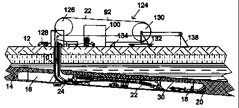
surface. Accordingly, Fig. 7 illustrates a set up that
could be used to implement this aspect of the invention.
It is noted that, in order to fully take advantage of the
movable belt and utility infrastructure of the invention,
all utility lines need to be lowered into or extracted
from the shaft 10 concurrently and at the same rate as the
mobile boot end moves forward or back from the cutting
face 20. Therefore, a system must be devised that
provides sufficient on-line storage of all excess utility
lines while in operation. As illustrated in Figs. 1 and
7, one such system comprises a central distribution and
extension or reduction station 100 from where all
utilities are provided through the cables and hoses
reaching underground in the bottom component 50 of the
infrastructure of the invention. For example, mine supply
water is fed to a water supply pipe 102 from a supply
water tank 104, and mine discharge water is returned to
the surface in a return pipe 106 and stored in a tank 108
for periodic discharge. Electrical power, provided by a
conventional substation 110, is delivered at different
voltages through appropriate power cables 112, and
hydraulic fluid is provided from a pumping station 114 in
a pipe 116. Similarly, though their sources are not shown
in the drawings, compressed air and telecommunication
wires are provided through a suitable pipe 118 and cable
120, as well as other utilities that may be needed
underground. All of these pipes and cables are combined
with conveyor belt provided to the station 100 in spools
122 in sufficient length to meet the on-line storage
requirements for continuous delivery to the mine. The on-
line storage for the belt and the various cables and
pipes, hereinafter collectively called "mining systems"
for simplicity, is provided by a take-up structure 124
comprising two large drums around which the mining systems
CA 02321064 2000-08-15
WO 99/41488 PCT/US99/03322
14
are looped between the distribution station 100 and mouth
of the shaft 10. A rotatable drum is mounted a stationary
unit 126 on top of the shaft 10 such that the mining
systems can be lowered into the shaft in continuous
fashion. As the mining systems advance underground and
are correspondingly lowered in the shaft 10, additional
units of the bottom component 50 delivered to the station
100, such as by trucks 128, are assembled around the belt
and various pipes and cables, as seen in Fig. 4, and
connected to each other to form a continuous, flexible
train of bottom-component structure ready to be connected
to units of the top component 48 underground. Behind the
drum on the stationary unit 126, the mining systems are
also looped around another rotatable drum on a mobile unit
130 mounted on a car 132 on rail tracks, such that its
position can be varied to increase or decrease its
distance from the stationary unit 126. Behind the mobile
unit 130, a braking unit 134 is provided to block the
movement of the mining systems from and to the station
100, where segments of belt, pipes and cables are added to
or removed from the system as needed. Given the fixed
position of the braking unit 134, the weight of the mining
systems hanging in the shaft 10 from the drum unit 126
would tend to pull the car 132 supporting the mobile drum
unit 130 toward the station 100. Therefore, a
counterweight 136 is provided to pull the car 132 in the
opposite direction through a cable/pulley unit 138.
From the configuration of the take-up unit 124, it is easy
to see how it provides a storage for the mining systems
equal to twice the distance between the nearest and
farthest positions the car 132 can reach between the
braking unit 134 and the cable/pulley unit 138. As the
mining systems are lowered into the shaft 10, the position
of the mobile drum unit 130 is adjusted proportionally to
maintain the appropriate tension in the mining systems
being fed to the mine. Obviously, when the mobile drum
CA 02321064 2000-08-15
WO 99/41488 PCT/US99/03322
unit 130 approaches the station 100 no additional length
of mining systems is available in storage. At that point,
new segments of pipes, cables and belt are spliced or
otherwise added to the mining systems and the mobile drum
5 unit 130 is moved away to provide proportionate storage
room.
During mine advance operations, the mobile boot end 34
seen in Figs. 1 and 3 is moved forward to keep up with the
10 continuous miner 18 cutting at the advancing face 20.
Prior to each step forward, the roof bolter 36 is used to
install new segments of rail 28 that enable the forward
progress of the train of structure modules 26 that carry
the belt and mining systems to the mobile boot end 34. As
15 the train of structure modules advances with the aid of
the tramming motors 74 (Fig. 4), the chain of bottom
components 50 assembled at the surface also advances
toward the mobile boot end 34 and is combined with a top
component 48 of structure at the underground assembly
station 86. In order to complete the assembly of each
module 26 at station 86 (see Fig. 2A), the roller wheel 72
is hung from the rail 28 and at least one of the clamps 70
is opened to allow the insertion of the top side of the
belt 22 between the hanging bracket 60 and the troughing
idler frame 62 (see Fig. 4). Then the clamps 70 are
secured in closed position and the top component 48 is
attached to the first free bottom component 50 using
clamps 52, thereby completing the addition of a new module
26 to the train of mine structure. Alternatively, as
illustrated in Fig. 2A, a troughing idler frame 62 is
first secured to each bottom component 50 reaching the
assembly station 86 and then attached to a hanging bracket
60 that has already been hung on the rail 28, thereby
producing a new structure module 26 that is ready to roll
with the rest of the train already in operation.
The surface-assisted continuous underground mining method
CA 02321064 2000-08-15
WO 99/41488 PCT/US99/03322
16
of the invention is fundamentally different from all
conventional underground or surface mining systems, where
belt structure and related mine support facilities are
added or removed in segments at predetermined stages of
mine advance or retreat, as applicable. The periodic
shutdowns attendant to conventional practice cause
significant loss of production time and corresponding
inefficiencies. In the case of underground mining, the
method of the invention also virtually eliminates the need
for storage and mining-systems extension work underground,
thereby greatly reducing underground haulage of materials
and the attendant support equipment, organization and
cost. As one skilled in the art would readily understand,
these advantages constitute a substantial improvement
over, and represent an exciting alternative to, the
methods of advancing and retreating underground mining
systems previously used in the art.
It is also noted that the system of the invention can be
implemented with similar advantages in a mine developed
through conventional in-seam entries, rather than through
a vertical shaft. Except for the aspect of the vertical
belt storage and take up unit, all other features of the
invention can be implemented in equivalent fashion through
horizontal or inclined entries to the mining face.
Similarly, all aspects of the invention described in terms
of advance mining, wherein belt, structure and mining
utility systems are added to continuously keep up with the
mining face, are also applicable to retreat mining,
wherein the same systems are continuously removed in
reverse fashion.
Various changes in the details, steps and components that
have been described may be made by those skilled in the
art within the principles and scope of the invention
herein illustrated. For example, in addition to coal, it
is clear that the concepts of the invention can be applied
CA 02321064 2000-08-15
WO 99/41488 PCT/US99/03322
17
to any mining situation where a mineral deposit is
embedded between strata at a depth suitable for mining by
conventional underground continuous mining equipment, or
in any situation where the cost of driving a shaft would
be justified by the improvements in productivity afforded
by the invention. Therefore, while the present invention
has been shown and described herein in what is believed to
be the most practical and preferred embodiments, it is
recognized that departures can be made therefrom within
the scope of the invention, which is not to be limited to
the details disclosed herein but is to be accorded the
full scope embraced by any and all equivalent processes
and products.