Note: Descriptions are shown in the official language in which they were submitted.
CA 02321241 2000-09-27
THE PREFABRICATION OF THE WAFFLE SLAB IN WAFER
FOUNDRY (FAB)
BACKGROUND OF THE INVENTION
Field of Invention
The present invention relates to a prefabrication of construction waffle slabs
in a
building and, in particular, to a prefabrication of the waffle slabs for a
wafer foundry.
Related Art
Upon rapid changes of the society, many operations have abandoned traditional
wisdom and routines. For example, the construction method has been changed in
such a way that standardized prefabricated products or effective assembly
methods
are employed so that all problems at the construction site such as safety,
sanitation,
schedule, gathering of technicians and sufficient materials can be improved.
However, not all constructions or civil engineering can be readily achieved by
prefabrication. It depends upon whether the methad satisfies the requirements
of
safety, cost, construction feasibility, and transportation etc. The
combination of
on-site construction and prefabrication has been widely adopted by architects
and
engineers as a valuable method to conquer all sorts of limitations. Thus,
prefabrication plays an important part in both civil engineering and building
construction.
Nowadays information technology has assumed the lead in global economy.
The need for wafers-the spinal core of information technology has increases
abruptly.
Therefore, the primary concern of investing wafer foundries is high efficiency
in the
process of construction. That is, aside from satisfying the civil engineering
code,
1
CA 02321241 2000-09-27
labor safety codes and etc, the ability in mastering the construction schedule
will
decide the profit for the investors. Usually, the wafer foundry or fab is
equipped
with waffle slabs for the installation of machines and devices. The waffle
slab is a
slab supported by pillars (or columns). In traditional fab slab construction,
the
pillars (or columns) are cast in place on the job field. Once the pillars (or
columns)
are constructed, wood molds and reinforced steel bars are assemble to be
topped with
concrete, therefore forming the slab. This method demands longer construction
period and may delay other construction works.
SUMMARY OF THE INVENTION
This invention manufactures the waffle slabs mentioned above for the
installation
of machines and devices in a prefabrication way so that they can be assembled
on site.
By assembling numbers of prefabricated pillars (or columns) and the
corresponding
prefabricated waffle slabs, aside from complying with various requirements for
installing all sorts of machines, this invention can also shorten the
construction
schedule to the optimal one and greatly reduce the on-site construction of the
waffle
slabs. Thus, we can achieve the goals of having a safe, fireproof, quake-
tolerant and
artistic structure with easy to transport, fast to construct prefabricated
waffle slabs.
BRIEF DESCRIPTION OF THE DRAWINGS
The invention is described in greater detail hereinafter relative to non-
limitative
embodiments and the attached drawings, wherein there is shown:
FIG. 1 is a top view of a waffle slab in a first embodiment of the invention;
FIG. 2 is a side view of a waffle slab in a first embodiment of the invention;
FIG. 3 is an isometric view of a waffle slab in a first embodiment of the
invention;
2
CA 02321241 2000-09-27
FIG. 4 is a reflected isometric view of a waffle slab in a first embodiment of
the
invention;
FIG. 5 is a top view of a waffle slab in a second embodiment of the invention;
FIG. 6 is a side view of a waffle slab in a second embodiment of the
invention;
FIG. 7 is an isometric view of a waffle slab in a second embodiment of the
invention;
FIG. 8 is a reflected isometric view of a waffle slab in a second embodiment
of
the invention;
FIG. 9 is a top view of a waffle slab in a third embodiment of the invention;
FIG. 10 is a side view of a waffle slab in a third embodiment of the
invention;
FIG. 11 is an~ isometric view of a waffle slab in a third embodiment of the
invention;
FIG. 12 is a reflected isometric view of a waffle slab in a third embodiment
of the
invention;
FIG. 13 is a top view of a waffle slab in a fourth embodiment of the
invention;
FIG. 14 is a side view of a waffle slab in a fourth embodiment of the
invention;
FIG. 15 is an isometric view of a waffle slab in a fourth embodiment of the
invention;
FIG. 16 is a reflected isometric view of a waffle slab in a fourth embodiment
of
the invention;
3
CA 02321241 2000-09-27
FIG. 17 is a top view of a waffle slab in a fifth embodiment of the invention;
FIG. 18 is a side view of a waffle slab in a fifth embodiment of the
invention;
FIG. 19 is an isometric view of a waffle slab in a fifth embodiment of the
invention;
S FIG. 20 is a reflected isometric view of a waffle slab in a fifth embodiment
of the
invention;
FIG. 21 is a top view of a resemblance waffle slab to the first embodiment of
the
invention;
FIG. 22 is a side view of a resemblance waffle slab to the first embodiment of
the
invention;
FIG. 23 is an isometric view of a resemblance waffle slab to the first
embodiment
of the invention;
FIG. 24 is a reflected isometric view of a resemblance waffle slab to the
first
embodiment of the invention;
FIG. 25 is a top view of a resemblance waffle slab to the second embodiment of
the invention;
FIG. 26 is a side view of a resemblance waffle slab to the second embodiment
of
the invention;
FIG. 27 is a isometric view of a resemblance waffle slab to the second
embodiment of the invention;
FIG. 28 is a reflected isometric view of a resemblance waffle slab to the
second
embodiment of the invention;
4
CA 02321241 2000-09-27
FIG. 29 is a top view of a resemblance waffle slab to the fifth embodiment of
the
invention;
FIG. 30 is a side view of a resemblance waffle slab to the fifth embodiment of
the
invention;
FIG. 31 is a isometric view of a resemblance waffle slab to the fifth
embodiment
of the invention; and
FIG. 32 is a reflected isometric view of a resemblance waffle slab to the
fifth
embodiment of the invention.
In the various drawings, the same references relate to the same elements.
DETAILED DESCRIPTION OF THE INVENTION
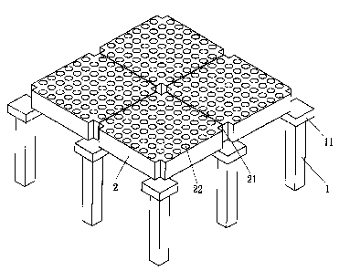
The prefabrication of waffle slabs for a fab (wafer foundry) is composed by
numbers of prefabricated pillars (or columns) ( 1 ), which have rectangular
capital on
top of each columns pillar (or column) (1) is positioned upright at the proper
position.
Square prefabricated waffle slabs (2-9) in various embodiments are placed on
the
prefabricated pillars (or columns) ( 1 ) so that notches on the four corners
of each
square prefabricated waffle slab 2-9 can be positioned on the capital (11) of
the pillars
(or columns) (1) either directly or by assembly. This method forms a wide
variety of
waffle slabs for a fab.
As shown in the drawings, the first through fourth embodiments and the first
and
second embodiment resemblance objects of the present invention are entirely
prefabricated. That is, these prefabrications of waffle slabs (2, 3, 4, 5 & 7,
8) are
prefabricated in the factory to their complete shapes. Once they are shipped
to the
5
CA 02321241 2000-09-27
construction site, one needs only to place them on the pillars (or columns)
(1) or
install them on the pillars (or columns) (1) through assembly elements without
the
need of tiding reinforced steel bars or pouring concrete. The fifth embodiment
of
the invention and the resemblance object are partially prefabricated. That is,
these
S prefabrications of waffle slabs (6, 9) are made partially into shape. The
waffle slabs
are then embedded with small cylinders (63) and/or multi-cylindrical post
connectors
(65). Once they are shipped to the construction site, reinforced steel bars
and
concrete are provided to complete the formation.
As shown in FIGS. 1 through 4, the square prefabricated waffle slab in the
first
embodiment of the invention has notches on four corners (21 ), regular
patterned holes
(22) are arranged on the upper surface and a rectangular hollow shape (23) on
the
back. Upon fulfilling the structural requirements, the hollow space can reduce
dead
loads and materials. The prefabricated waffle slab (2) are securely positioned
among
all arranged pillars (or columns) ( 1 ) to form a safe structure of the waffle
slab for a
1 S fab.
As shown in FIGS. 5 through 8, ladder-shape auxiliary (31) that is formed with
holes (32) are introduced to accurately place the trapezoid-shaped waffle
slabs
longitudinally and transversely on top of prefabricated pillars (or columns)
(1). The
T-shape prefabricated waffle slabs (3) are then placed into the corresponding
ladder-shape auxiliary (31 ) for its proper positioning. The upper surface of
this
T-shape prefabricated waffle slab (3) is cast with cylindrical holes (33) and
the back
surface of it is equipped with reinforced beams (plates) (34).
As shown in FIGS. 9 through 12, dove-tail-shape auxiliary (41) are installed
transversely on the prefabricated pillars (or columns) (1). The rib-shape
prefabricated waffle slab (4) of the third embodiment is then installed and
positioned
on the dove-tail-shape auxiliary (41) by both ends. The upper surface of the
6
CA 02321241 2000-09-27
rib-shape prefabricated waffle slab (4) is fabricated with numbers of ribbed
plates (42)
and the back of it is equipped with trapezoid-shaped reinforced beams (or
plates)
(43).
As shown in FIGS. 13 through 16, the M-shape prefabricated waffle slab has
employed T-shape auxiliary (51 ) which has protruding blocks (52) that is to
be
installed transversely on the positioned prefabricated pillars (or columns)
(1). The
M-shape prefabricated waffle slab (5) is then installed in the right position
by
matching both ends onto the protruding blocks (52) of the T-shape auxiliary
(51).
The upper surface of the M-shape prefabricated waffle slab (5) is cast with
square
holes (53) and the back of it is equipped with trapezoid-shaped reinforced
beams (or
plates) (54).
As shown in FIGS. 17 through 20, a thin slab shape (61) is introduced as the
upper rim in the partially prefabricated disk-shape waffle slab (6) of the
fifth
embodiment. The thin slab shape (61 ) which is cast with numbers of
cylindrical
holes (62) for the embedding of small cylinders (63) (auxiliary cylinders made
of
lightweight plastic) that will bond with the disk-shape prefabricated waffle
slab (6).
The central portion is formed with square troughs (64) to be embedded with the
multi-cylindrical post connectors (65) which will bond with the disk-shape
prefabricated waffle slab (6) also. The finished object of the partially
prefabricated
embodiment is shown in FIG. 19. Once they are shipped to the construction site
and
installed on the pillars (or columns) ( 1 ), concrete is then provided to form
a slab just
like the entirely prefabricated waffle slab (2) in the first embodiment shown
in FIG. 3.
The characteristic of the partially prefabricated waffle slab is that it has a
lighter
weight than the entirely prefabricated one under certain strength
requirements.
Therefore, the transportation, shipping and construction of the slabs are
easier than
the entirely prefabricated ones. Furthermore, the conjunctions of the
partially
7
CA 02321241 2000-09-27
prefabricated waffle slabs are simpler than the entirely prefabricated slabs.
However,
the disadvantage is that one needs to place reinforced steel bars and to cast
concrete
on the site.
As shown in FIGS. 21 through 24, the square prefabricated waffle slab (7) can
be
made in resemblance of square prefabricated waffle slab (2) in the first
embodiment.
More explicitly, the resembled square prefabricated waffle slab (7) is made as
a solid
with cylindrical holes (71 ) distributed thereon.
As shown in FIGS. 25 through 28, the square prefabricated waffle slab (8) can
be
made in resemblance of T-shape prefabricated waffle slab (3) of the second
embodiment. More explicitly, the ladder-shape auxiliary (31 ) is has not been
changed, but the resembled square prefabricated waffle slab (8) is made into
solid
with through cylindrical holes (81 ) thereon.
As shown in FIGS. 29 through 32, the partially prefabricated disk-shape waffle
slab (9) can be made in resemblance of the partially prefabricated disk-shape
waffle
slab (6) of the fifth embodiment. More explicitly, the rectangular holes (67)
in the
central portion are changed into a row of cylindrical holes (91 ) on the
resembled
partially prefabricated square waffle slab (9), which can be embedded with
small
cylinders (63). This will end up with the same results as in the entirely
prefabricated
structure in the fifth embodiment. Under a certain strength requirement, this
has
lighter weight than the entirely prefabricated one, which had the advantage of
easier
conjunction.
Using the prefabricated waffle slabs 2-9 in the above embodiments and the
accompanying pillars (or columns) (1), the described structure of the waffle
slabs for
the fab will very well achieve the goals in safety control, fire proof, quake
tolerance
and fast construction.
8
CA 02321241 2000-09-27
The invention being thus described, it will be obvious that the same may be
varied in many ways. Such variations are not to be regarded as a departure
from the
spirit and scope of the invention, and all such modifications as would be
obvious to
one skilled in the art are intended to be included within the scope of the
following
claims.
9