Note: Descriptions are shown in the official language in which they were submitted.
CA 02321284 2000-08-17
WO 99/42708 PCTIUS99/02295
-1- -
5
The present invention relates generally to a
method of operating a diesel engine, and more
particularly to a method of operating a diesel engine
10 by injecting into a combustion chamber thereof a pilot
volume of an emulsified diesel fuel prior to injecting
a main volume of the emulsified diesel fuel.
15 It is desirable under certain circumstances
to operate a diesel engine on a low cetane fuel.
However, low cetane fuels typically have poor ignition
quality. Specifically, low cetane fuels generally
have relatively long ignition delays. That is, a
20 relatively long period of time elapses between the
time the low cetane fuel is injected into a combustion
chamber of the diesel engine and the time the low
cetane fuel actually ignites.
Accordingly, one draw back to utilizing low
25 cetane fuels is that their relatively long ignition
delays cause starting problems in diesel engines. In
addition, the long ignition delay can cause the diesel
engine to misfire under light loads.
What is needed therefore is a method of
34 operating a diesel engine on a low cetane fuel which
CA 02321284 2000-08-17
WO 99/42708 PCTIUS99102Z95
-2- -
overcomes one or more of the above-mentioned
drawbacks.
p;acl~~mre of the Invention
5 In accordance with a first embodiment of the
present invention, there is provided a method of
operating a diesel engine, with the diesel engine
having (i) a combustion chamber, and (ii) a fuel
injector having an injection port positioned in fluid
10 communication with the combustion chamber. The method
includes the steps of (A) injecting a pilot volume of
an emulsified diesel fuel into the combustion chamber
with the fuel injector, (B) compressing the pilot
volume of the emulsified diesel fuel within the
15 combustion'chamber during a compression stroke of the
diesel engine, and (C) injecting a main volume of the
emulsified diesel fuel into the combustion chamber
with the fuel injector, whereby heat generated by
compression of the pilot volume of the emulsified
20 diesel fuel causes the pilot volume of the emulsified
diesel fuel to combust so as to ignite the main volume
of the emulsified diesel fuel.
In accordance with a second embodiment of
the present invention, there is provided a method of
25 operating a diesel engine. The method includes the
steps of (A) injecting a pilot volume of an emulsified
diesel fuel into a combustion chamber of the diesel
engine, wherein the emulsified diesel fuel includes
water and diesel fuel, (B) compressing the pilot
30 volume of the emulsified diesel fuel within the
CA 02321284 2000-08-17
WO 99/42708 PCTIUS99102295
_3_ _._
combustion chamber during a compression stroke of the
diesel engine, and (C) injecting a main volume of the
emulsified diesel fuel into the combustion chamber
during the compression stroke of the diesel engine,
5 whereby heat generated by compression of the pilot
volume of the emulsified diesel fuel causes the pilot
volume of the emulsified diesel fuel to combust so as
to ignite the main volume of the emulsified diesel
fuel.
10 In accordance with a third embodiment of the
present invention, there is provided a method of
operating a diesel engine, with the diesel engine
having a fuel injector. The method includes the steps
of (A) injecting a pilot volume of an emulsified
15 diesel fuel into a combustion chamber of the diesel
engine with the fuel injector, wherein the emulsified
diesel fuel includes water and diesel fuel, (B)
compressing the pilot volume of the emulsified diesel
fuel within the combustion chamber during a
20 compression stroke of the diesel engine, and (C)
injecting a main volume of the emulsified diesel fuel
into the combustion chamber with the fuel injector
during the compression step, whereby heat generated by
compression of the pilot volume of the emulsified
25 diesel fuel causes the pilot volume of the emulsified
diesel fuel to combust so as to ignite the main volume
of the emulsified diesel fuel.
CA 02321284 2000-08-17
WO 99142708 PCT/US99/02295
-4 - ...
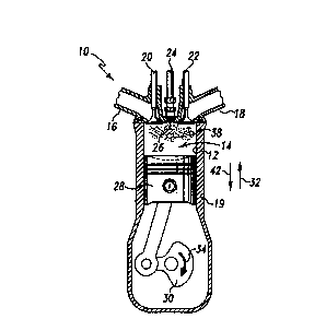
FIG. 1 is a fragmentary side elevational
view, partially in cross section, of a diesel engine
which incorporates the features of the present
5 invention therein, with the engine shown during an
intake stroke;
FIG. 2 is a view similar to FIG. l, but
showing the engine during a compression stroke; and
FIG. 3 is a view similar to FIG. 2, but
10 showing the engine at a later part of the compression
stroke as compared to FIG. 2.
While the invention is susceptible to
15 various modifications and alternative forms, a
specific embodiment thereof has been shown by way of
example in the drawings and will herein be described
in detail. It should be understood, however, that
there is no intent to limit the invention to the
20 particular form disclosed; but on the contrary, the
intention is to cover all modifications, equivalents,
and alternatives falling within the spirit and scope
of the invention as defined by the appended claims.
Referring now to FIG. 1, there is shown a
25 fragmentary side elevational view, partially in cross
section, of a four stroke diesel engine 10. Engine 10
includes a piston 28 and a crankshaft 30 operatively
coupled to piston 28. Piston 28 is positioned in a
cylinder 12 defined in an engine block 19 of the
30 engine 10. Cylinder 12 defines a combustion chamber
CA 02321284 2000-08-17
WO 99/42708 PCT/US99/02295
-5-
14. Engine 10 further includes a fuel injector 24.
Fuel injector 24 has an injection port 26 which is in
fluid communication with cylinder 12.
In addition, fuel injector 24 is
5 electrically coupled to an engine control module (not
shown) in order to control a staged injection into
combustion chamber 14 of (i) a pilot volume 38 of an
emulsified diesel fuel (see FIG. 2) and (ii) a main
volume 40 of the emulsified diesel fuel (see FIG. 3).
10 What is meant herein by the term "pilot
volume" (i.e. pilot volume 38) is a volume of
emulsified diesel fuel which when combusted in
combustion chamber 14 would be effective to ignite a
substantially greater volume (i.e. main volume 40) of
15 the emulsified diesel fuel which is injected into
combustion chamber 14 at about the same time the pilot
volume is combusting. It should be appreciated that
the pilot volume injected into combustion chamber 14
by fuel injector 24 represents a quantity (i.e. a
20 volume) of emulsified diesel fuel which contributes
about 1% to about 5% of the total amount of energy
released by the combustion of the combination of (i)
the emulsified diesel fuel contained in pilot volume
38, and (ii) the emulsified diesel fuel contained in
25 main volume 40. For example, the pilot volume 38 may
equal about 1.0% to about 5.0% of the total volume
(i.e. 100%) of the emulsified diesel fuel that fuel
injector 24 injects into combustion chamber 14 during
one engine cycle.
CA 02321284 2000-08-17
WO 99/42708 PCT/US99/02295
-6- -
What is meant herein by the term "main
volume" is a volume of emulsified diesel fuel which is
substantially greater than the pilot volume and which
when combusted within combustion chamber 14 is
5 effective to drive the crankshaft 30 into rotation to
achieve normal operation of an engine. It should be
appreciated that the main volume injected into
combustion chamber 14 by fuel injector 24 represents a
quantity (i.e. a volume) of emulsified diesel fuel
10 which contributes about 95% to about 99% of the total
amount of energy released by the combustion of the
mixture of (i) the emulsified diesel fuel contained in
pilot volume 38, and (ii) the emulsified diesel fuel
contained in main volume 40. For example, the main
15 volume 40 may equal to about 95% to about 99% of the
total volume {i.e. 100%) of the emulsified diesel fuel
that fuel injector 24 injects into combustion chamber
14 during one engine cycle.
Therefore, it should be appreciated that if
20 during one engine cycle, the pilot volume 38 is equal
to about 1% of the total volume of the emulsified
diesel fuel injected into combustion chamber 14, then
the main volume 40 would be equal to about 99% of the
total volume of the emulsified diesel fuel injected
25 into combustion chamber 14 during one engine cycle.
Correspondingly, if the pilot volume 38 is equal to
about 5% of the total volume of the emulsified diesel
fuel injected into combustion chamber 14 during one
engine cycle, then the main volume 40 would be equal
30 to 95% of the total volume of the emulsified diesel
CA 02321284 2000-08-17
WO 99142708 PCT/US99/02295
fuel injected into combustion chamber 14 during one
engine cycle.
The emulsified diesel fuel is a low cetane
fuel which includes water and liquid fuel.
5 Preferably, the liquid fuel is diesel fuel. Moreover,
in order to provide meaning to the term "water" as it
is used in this document, the term "water" is used to
mean a quantity of water in a mixture wherein the
weight percentage of water in the mixture is more than
10 a deminimis amount which would normally occur in a
liquid (such as diesel fuel alone) as a result of the
liquid being exposed to its ambient surroundings
during processing, transportation, and use thereof.
For example, the emulsified diesel fuel is preferably
15 an emulsion of water in diesel fuel at a water to fuel
ratio of about X% water by weight, where 5 < X < 60,
and more preferably where 10 < X < 50. In addition,
the emulsified diesel fuel may have (i) the water as
the continuous phase and the diesel fuel as the
20 discontinuous phase, or alternatively (ii) the diesel
fuel as the continuous phase and the water as the
discontinuous phase. Moreover, the emulsified diesel
fuel may include any appropriate emulsifying agent.
Engine 10 also includes a valve 20 having a
25 rocker arm (not shown) and a push rod (not shown)
operatively associated therewith. In addition, engine
10 also includes a valve 22 having a rocker arm (not
shown) and a push rod (not shown) operatively
associated therewith. Valves 20 and 22, are
30 operatively associated with cylinder 12. Engine 10
CA 02321284 2000-08-17
WO 99/42708 PGT/US99/02295
_g_ ._
also includes an air intake conduit 16 which is in
fluid communication with cylinder 12. Engine 10
further includes an exhaust conduit 18 which is in
fluid communication with cylinder 12.
5 As previously mentioned, engine 10 is a four
stroke diesel engine. The first stroke is an intake
stroke (see FIG. 1) in which rotation of a cam (not
shown) actuates the rocker arm (not shown) and the
push rod (not shown) operatively associated with valve
10 20 such that valve 20 is moved in a direction
indicated by arrow 42. Moving valve 20 in the
direction indicated by arrow 42 places cylinder 12 in
fluid communication with air intake conduit 16.
Placing cylinder 12 in fluid communication with air
15 intake conduit 16 allows air to be advanced into
cylinder 12 (and therefore combustion chamber 14) as
crankshaft 30 rotates in a direction indicated by
arrow 34 thus causing piston 28 to travel in a
direction indicated by arrow 32.
20 As shown in FIG. 2, once the intake stroke
is complete, engine 10 advances to a compression
stroke. During the compression stroke, valve 20 is
positioned such that air intake conduit 16 is isolated
from fluid communication with cylinder 12, and
25 crankshaft 30 causes piston 28 to travel in a
direction indicated by arrow 32. During the
compression stroke, the engine control module (not
shown) generates a pilot output signal thereby
actuating fuel injector 24 so as to start an injection
30 (via injection port 26) of a pilot volume 38 of the
CA 02321284 2000-08-17
WO 99/42708 PCT/US99I02295
_g_ _._
emulsified diesel fuel into cylinder 12. Preferably,
the injection of pilot volume 38 of the emulsified
diesel fuel into cylinder 12 is started when
crankshaft 30 is positioned between about 2° to about
5 120° before top dead center (BTDC) during the
compression stroke as shown in FIG. 2. Injection of
pilot volume 38 of the emulsified diesel fuel into
cylinder 12 creates a mixture within cylinder 12 which
includes (i) air, and (ii) the emulsified diesel fuel.
10 Near the top of the compression stroke, the heat
generated as a result of compressing the
aforementioned mixture causes the pilot volume 38 of
the emulsified diesel fuel contained in the combustion
chamber 14 to combust.
15 As shown in FIG. 3, at about the same time
as the pilot volume 38 of the emulsified combusts, the
engine control module (not shown) generates a main
output signal thereby actuating fuel injector 24 so as
to start an injection of a main volume 40 of the
20 emulsified diesel fuel into cylinder 12. In
particular, the injection of the main volume 40 of the
emulsified diesel fuel into cylinder 12 is started
when crankshaft 30 is positioned between about 18° to
about 0° before top dead center (BTDC) during the
25 compression stroke of engine 10 as shown in FIG. 3.
It should be understood that 0° BTDC represents the
position of crankshaft 30 at top dead center (TDC).
In addition, it should be understood that the
injection of main volume 40 can be started when
30 crankshaft 30 is positioned past TDC (i.e. during the
CA 02321284 2000-08-17
WO 99/42708 PCT/US99102295
-10- 3--
power stroke of engine 10). Specifically, the
injection of main volume 40 can be started during the
power stroke of engine 10 when crankshaft 30 is
positioned at about 1° to about 5° past TDC.
5 Combustion of the pilot volume 38 of the emulsified
diesel fuel causes the main volume 40 of the
emulsified diesel fuel to ignite.
Ignition and then the subsequent combustion
of the pilot volume 38 and the main volume 40 of the
10 emulsified diesel fuel causes exhaust gases to be
formed in the combustion chamber 14. During the power
stroke, the piston 28 is driven in the direction
indicated by arrow 42 by the exhaust gases so as to
rotate crankshaft 30 in the direction indicated by
15 arrow 34.
Thereafter, engine 10 is advanced to an
exhaust stroke (not shown) in which another push rod
(not shown) is actuated by a cam (not shown) so as to
open valve 22 and place cylinder I2 in fluid
20 communication with exhaust conduit 18. The exhaust
gases formed from the combustion of the pilot volume
38 and the main volume 40 of the emulsified diesel
fuel are then advanced from cylinder 12 to exhaust
conduit 18 by the movement of piston 28 in the
25 direction indicated by arrow 32 during the exhaust
stroke.
Collectively, the intake stroke, the
compression stroke, the power stroke, and the exhaust
stroke are included in one engine cycle of engine 10.
CA 02321284 2000-08-17
WO 99142708 PCTNS99/02295
-11- yw
Once the exhaust stroke is completed, the intake
stroke is repeated to initiate another engine cycle.
TnduBt_ria~ A~nlicabilitv
5 It should be appreciated that the
aforementioned problems associated with long ignition
delays caused by use of low cetane fuels can be
overcome by uae of the present invention. In
particular such problems can be overcome by (i)
10 injecting the pilot volume 38 of the emulsified diesel
fuel into the combustion chamber 14 with the fuel
injector 24, (ii) compressing the pilot volume 38 of
the emulsified diesel fuel within the combustion
chamber 14 during the compression stroke of the engine
15 10, and (iii) injecting the main volume 40 of the
emulsified diesel fuel into the combustion chamber 14
with the fuel injector 24 so that heat generated by
compression of the pilot volume 38 of the emulsified
diesel fuel causes the pilot volume 38 to combust so
20 as to ignite the main volume 40 of the emulsified
diesel fuel. It should be noted that a period of time
elapses between injection of the pilot volume 38 of
the emulsified diesel fuel into the combustion chamber
14 and injection of the main volume 40 of the
25 emulsified diesel fuel into the combustion chamber 14.
While the invention has been illustrated and
described in detail in the drawings and foregoing
description, such illustration and description is to
be considered as exemplary and not restrictive in
30 character, it being understood that only the preferred
CA 02321284 2000-08-17
WO 99/42708 PCT/US99/02295
_'
embodiment has been shown and described and that all
changes and modifications that come within the spirit
of the invention are desired to be protected.