Note: Descriptions are shown in the official language in which they were submitted.
CA 02321333 2000-09-28
WRITING IMPhEMENT
BACKGROUND OF THE INVENTION
1. Field of the Invention
The present invention relates to a writing implement.
In detail, the invention relates to a writing implement which
comprises a shaft barrel storing ink in an interior portion
thereof and a plug body ( for example, a tail plug or a pen point
hold body) removably mounted on one end of the shaft barrel.
In the present invention, a term "front" means the pen point
side of the writing implement, whereas a term "rear" means the
tail plug side thereof. Also, an expression "front surface"
means the axial-direction outer surface of the writing implement,
whereas an expression "back surface" means the axial-direction
inner surface thereof.
2. Description of the Related Art
Conventionally, for example, in Japanese Patent Unexamined
Publication No. Hei. 11-48679, there is disclosed a writing
implement in which, for the purpose of removing an ink storing
body stored into an interior portion of a shaft barrel, a tail
plug is removably mounted on an opening formed in a rear end
portion of the shaft barrel. Further, between a flange portion
of the tail plug and the rear end portion of the shaft barrel,
- 25 there is formed a groove (a cutaway portion) into which a coin
such as a ten-yen coin or a tool can be engaged. By engaging
the coin into the groove, the tail plug can be forced open.
1
CA 02321333 2000-09-28
Also, in the above-cited publication, there is alsodisclosed
a writing implement in which a pen point hold body including
a pen point is removably mounted on an opening formed at a front
end portion of a shaft barrel. Between a flange portion of
the pen point hold body and the front end portion of the shaft
barrel, there is formed a groove (a cutaway portion) similar
to the above-mentioned structure.
However, in the above-mentioned conventional writing
implements, since the groove for forcible opening is shallow
inwardly in a diameter direction thereof, when forcing open
the tail plug or pen point hold body, the coin or tool can be
inserted into the groove only in a small amount. Namely, the
tail plug or pen point hold body cannot be forced open easily;
or, a large force is necessary to force open the tail plug or
pen point hold body. Therefore, there is a fear that the end
portion of the shaft barrel, the flange portion of the tail
plug, or the flange portion of the pen point hold body can be
damaged.
SUMMARY OF THE INVENTION
The present invention aims at solving the problems found
in the above-mentioned conventional writing implements.
Accordingly, it is an obj ect of the invention to provide a writing
implement in which a tail plug or pen point hold body can be
easily removed from an end portion of a shaft barrel. Thus
the end portion of the shaft barrel, a flange portion of the
tail plug, or a flange portion of the pen point hold body can
2
CA 02321333 2006-03-20
be fully prevented against damage.
[1] A writing implement, according to a first aspect of
the invention, comprises: a shaft barrel storing ink in an
interior portion thereof and having an opening at one end
portion thereof; and a plug body removably mounted on the
opening of the shaft barrel, the plug body comprising: a
flange portion provided outwardly in an axial direction of
the shaft barrel from the one end portion of the shaft
barrel. In the writing implement, a forcibly opening groove
is formed between one surface of the flange portion and the
one end portion of the shaft barrel, the forcibly opening
groove being formed more deeply inwardly in a diameter
direction of the shaft barrel than an inner surface of the
one end portion of the shaft barrel.
Figures 1 to 8 are introduced on page 13 of this
disclosure and described on pages 13 to 26 with reference to
reference numerals. The same reference numerals are used to
describe similar elements in the following paragraphs forming
the remainder of this Summary of the Invention.
(Operation)
Since the forcibly opening groove 5, 5' is formed more
deeply inwardly in the diameter direction of the shaft barrel
4 than the inner surface of one end opening of the shaft
barrel 4, in case where a tool 9 such as a coin is inserted
into the groove 5, 5', the diameter-direction inner end
portion of the tool 9 is positioned more deeply than the
inner surface of the one end opening of the shaft barrel 4.
Therefore, as shown in Figs. 1 and 7, in case where the
diameter-direction outer end portion of the tool 9 is pushed
inwardly in the axial direction of the tool 9 with one end
portion of the shaft barrel 4 as a fulcrum thereof, the
surface of the diameter-direction inner end portion of the
tool 9 is pressed
3
CA 02321333 2006-03-20
against the back surface of the flange portion 21, 31 outwardly
in the axial direction thereof. Namely, the plug body 2, 3
can be removed easily from one end opening of the shaft barrel
4 with a slight force. Also, not only by the above-mentioned
forcibly opening method, as shown in Figs . 6 and 8, by twisting
a tool 9 which is inserted into the groove 5, 5' , the plug body
2, 3 can be removed easily from one end opening of the shaft
barrel 4.
Since the plug body 2, 3 can be removed easily from one
end opening of the shaft barrel 4 using the tool 9, one end
portion of the shaft barrel 4 as well as the flange portion
21, 31 of the plug body 2, 3 can be prevented against damage.
At the same time, the mutual connection between the shaft barrel
4 and plug body 2, 3 can be strengthened. Therefore, unless
a forcibly opening operation is executed using the tool 9, the
plug body 2, 3 cannot. be removed easily, which makes it possible
to prevent the plug body 2, 3 against removal.
[2] According to a second aspect of the invention, in
the writing implement 1 according to the first aspect of the
invention, preferably, the plug body may further comprise: a
fitting tubular portion fitted with the inner surface of the
shaft barrel; and a connecting portion connecting together the
fitting tubular portion and the flange portion, wherein a space
is formed between an outer surface of the connecting portion
and the inner surface of the one end portion of the shaft barrel,
and connected to the forcibly opening groove.
(Operation)
4
CA 02321333 2006-03-20
Due to this structure, when removing the plug body 2, 3
using the forcibly opening operation (that is, the pressing
operation or twisting operation) of the tool 9, the space 6,
6' provides an escape space for the plug body 2, 3 with respect
to the tool 9. This makes it possible to prevent the back surface
of the diameter-direction inner end portion of the tool 9 from
being abutted on one end portion of the fitting tubular portion
23, 33 of the plug body 2, 3. Also, this makes it possible
to separate the shaft barrel 4 and plug body 2, 3 greatly from
each other simply by the forcibly opening operation of the tool
9, so that the removing operation of the plug body 2, 3 can
be facilitated further.
[3] According to a third aspect of the invention, in
the writing implement 1 according to the second aspect of the
invention, preferably, the plug body may further comprise:
a plurality of reinforcing ribs provided on the outer surface
of the connecting portion, each of the reinforcing ribs extending
in an axial direction of the plug body for connecting together
the flange portion and the fitting tubular portion.
(Operation)
Due to this structure, the forcibly opening groove 5, 5'
formed between one end portion of the shaft barrel 4 and the
flange portion 21, 31 can be positioned between the respective
reinforcing ribs 24, 34. At the same time, in the forcibly
opening operation, the flange portion 21, 31 can be prevented
from being unstable with respect to the fitting tubular portion
23, 33, so that the plug body 2, 3 can be removed in a stable
5
CA 02321333 2006-03-20
manner.
[ 4 ] According to a fourth aspect of the invention, in
the writing implement 1 according to the first aspect of the
invention, the shaft barrel has a pen point at a front end thereof,
the plug body is removably mounted on an opening formed at a
rear end portion of the shaft barrel, and the flange portion
is provided backwardly of the rear end portion of the shaft
barrel, wherein the forcibly opening groove is formed between
the one surface of the flange portion and the rear end portion
of the shaft barrel, the forcibly opening groove being formed
more deeply inwardly in the diameter direction of the shaft
barrel than an inner surface of the rear end portion of the
shaft barrel. (See Figs. 1 to 6).
(Operation)
Due to this structure, since the forcibly opening groove
5 is formed more deeply inwardly in the diameter direction of
the shaft barrel 4 than the inner surface of the rear end opening
of the shaft barrel 4, in case where the tool 9 such as a coin
is inserted into the groove 5, the inner end portion of the
tool 9 can be positioned more deeply than the inner surface
of the rear end opening of the shaft barrel 4.
Therefore, as shown in Fig. l, in case where the outer
end portion of the tool 9 is pushed forwardly with the rear
end portion of the shaft barrel 4 as a fulcrum thereof, the
rear surface of the inner end portion of the tool 9 is pressed
against the front surface (back surface) of the flange portion
21 backwardly. Namely, the tail plug 2 (plug body) can be easily
6
CA 02321333 2000-09-28
removed from the rear end opening of the shaft barrel 4 with
a slight force. Also, besides the above-mentioned forcibly
opening method, as shown in Fig. 6, using the twisting operation
of the tool 9 inserted into the groove 5, the tail plug 2 can
also be easily removed from the rear end opening of the shaft
barrel 4.
Due to the fact that the tail plug 2 can also be easily
removed from the rear end opening of the shaft barrel 4 using
the tool 9, the rear end portion of the shaft barrel 4 and the
flange portion 21 of the tail plug 2 can be prevented against
damage. At the same time, the mutual connection between the
shaft barrel 4 and tail plug 2 can be strengthened. Thus, unless
a forcibly opening operation is executed using the tool 9, the
tail plug 2 cannot be removed from the shaft barrel 4 easily,
which can prevent the tail plug 2 from dropping off the shaft
barrel 4.
Since the tail plug 2 can be mounted into and removed from
the rear end opening of the shaft barrel 4, ink can be replenished
into an ink storing body or an ink tank stored within the shaft
barrel 4 through the rear end portion of the shaft barrel 4
with the tail plug 2 removed. The ink storing body or ink tank
stored within the shaft barrel 4 can be removed from the shaft
barrel 4 and can be replaced with new one, or the ink storing
body or ink tank removed can be filled with ink again.
- 25 [5] According to a fifth aspect of the invention, in a
writing implement according to the fourth aspect of the invention,
preferably, the space may be formed between the outer surface
7
CA 02321333 2006-03-20
of the connecting portion and the inner surface of the rear
end portion of the shaft barrel.
(Operation)
Due to this structure, when removing the tail plug 2 using
the forcibly opening operation (that is, the pressing operation
or twisting operation) of the tool 9, the space 6 provides an
escape space for the tail plug 2 with respect to the tool 9.
This makes it possible to prevent the front surface of the
inner end portion o.f the tool 9 from being abutted on the rear
end portion of the fitting tubular portion 23 of the tail plug
2. Also, this makes it possible to separate the shaft barrel
4 and tail plug 2 greatly from each other simply by the forcibly
opening operation of the tool 9, so that the removing operation
of the tail plug 2 can be facilitated further.
[6) According to a sixth aspect of the invention, in the
writing implement 1 according to the fifth aspect of the invention,
preferably, the plug body may further comprise:
a plurality of reinforcing ribs provided on the outer surface
of the connecting portion, each of the reinforcing ribs extending
in an axial direction of the plug body for connecting together
the flange portion and the fitting tubular portion.
(Operation)
Due to this structure, the forcibly opening groove 5 formed
between the rear end portion of the shaft barrel 4 and the flange
portion 21 can be positioned between the respective reinforcing
ribs 24. At the same time, in the forcibly opening operation,
the flange portion 21 can be prevented from being unstable with
s
CA 02321333 2006-03-20
respect to the fitting tubular portion 23, so that the tail
plug 2 can be removed in a stable manner.
Each of the reinforcing ribs 24 may preferably include
a stepped portion 24a to be abutted on the rear end portion
of the shaft barrel 4 (that is, it may include a stopper function
with respect to the rear end portion of the shaft barrel 4).
Due to this, the forcibly opening groove 5 can be positively
formed between the flange portion 21 and the rear end portion
of the shaft barrel 4.
[7] According to a seventh aspect of the invention, in
the writing implement 1 according to the first aspect of the
invention, the plug body is removably mounted in an opening
formed at a front end of the shaft barrel and has a pen point,
and the flange portion is provided forwardly of the front end
portion of the shaft barrel, wherein the forcibly opening groove
is formed between t:he one surface of the flange portion and
the front end portion of the shaft barrel, the forcibly opening
groove being formedmore deeply inwardly in the diameter direction
of the shaft barrel than an inner surface of the front end portion
of the shaft barrel. (See Figs. 7 and 8).
(Operation)
Due to this structure, since the forcibly opening groove
5' is formed more deeply inwardly in the diameter direction
of the shaft barrel 4 than the inner surface of the rear end
opening of the shaft barrel 4, in case where the tool 9 such
as a coin is inserted into the groove 5' , the inner end portion
of the tool 9 can be positioned more deeply than the inner surface
9
CA 02321333 2000-09-28
of the front end opening of the shaft barrel 4.
Therefore, as shown in Fig. 7, in case where the outer
end portion of the tool 9 is pushed backwardly with the front
end portion of the shaft barrel 4 as a fulcrum thereof, the
front surface of the inner end portion of the tool 9 is pressed
against the rear surface (back surface) of the flange portion
31 forwardly. Namely, the pen point hold body 3 (plug body)
can be easily removed from the front end opening of the shaft
barrel 4 with a slight force. Also, besides the above-mentioned
forcibly opening method, as shown in Fig. 8, by twisting the
tool 9 which is inserted into the groove 5' , the pen point hold
body 3 can also be easily removed from the front end opening
of the shaft barrel 4.
Due to the fact that the pen point hold body 3 can also
be easily removed from the front end opening of the shaft barrel
4 using the tool 9, the front end portion of the shaft barrel
4 and the flange portion 31 of the pen point hold body 3 can
be prevented against damage. At the same time, the mutual
connection between the shaft barrel 4 and pen point hold body
3 can be strengthened. Thus, unless a forcibly opening operation
is executed using the tool 9, the pen point hold body 3 cannot
be removed from the shaft barrel 4 easily, which can prevent
the pen point hold body 3 from dropping off the shaft barrel
4.
Since the pen point hold body 3 can be mounted into and
removed from the front end opening of the shaft barrel 4, ink
can be replenished into an ink storing body or an ink tank stored
CA 02321333 2006-03-20
within the shaft barrel 4 through the front end portion of the
shaft barrel 4 with the pen point hold body 3 removed. The
ink storing body or ink tank stored within the shaft barrel
4 can be removed from the shaft barrel 4 and can be replaced
with new one, or the ink storing body or ink tank removed can
be filled with ink again.
The writing implement according to the seventh aspect of
the invention, may further comprise: a rear plug body remevably
mounted in an opening formed at a rear end portion of the shaft
barrel, the rear plug body including a rear pen point and a
rear flange portion provided backwardly of the rear end portion
of the shaft barrel, wherein a rear forcibly opening groove
is formed between one surface of the rear flange portion and
the rear end portion of the shaft barrel, the rear forcibly
opening groove being formed more deeply inwardly in the diameter
direction of the shaft barrel than an inner surface of the rear
end portion of the shaft barrel.
'[8] According to a eighth aspect of the invention, in
the writing implement 1 according to the seventh aspect of the
invention, preferably, the space may be formed between the outer
surface of the connecting portion and the inner surface of the
front end portion of the shaft barrel.
(Operation)
Due to this structure, when removing the pen point hold
body 3 using the forcibly opening operation (that is, pressing
operation or twisting operation) of the tool 9, the space 6
provides an escape space for the pen point hold body 3 with
11
CA 02321333 2006-03-20
respect to the tool 9. This makes it possible to prevent the
rear surface of the inner end portion of the tool 9 from being
abutted on the front end portion of the fitting tubular portion
33 of the pen point hold body 3. Also, this makes it possible
to separate the shaft barrel 4 and pen point hold body 3 greatly
from each other simply by the forcibly opening operation of
the tool 9, so that the removing operation of the pen point
hold body 3 can be facilitated further.
[9] According to a ninth aspect of the invention, in the
writing implement 1 according to the eighth aspect of the invention,
preferably, the plug body may further comprise: a plurality
of reinforcing ribs provided on the outer surface of the connecting
portion, each of the reinforcing ribs extending in an axial
direction of the plug body for connecting together the flange
portion and the fitting tubular portion.
Due to this structure, the forcibly opening groove 5' formed
between the front end portion of the shaft barrel 4 and the
flange portion 31 can be positioned between the respective
reinforcing ribs 34. At the same time, in the forcibly opening
operation, the flange portion 31 can be prevented from being
unstable with respect to the fitting tubular portion 33, so
that the pen point hold body 3 can be removed in a stable manner.
Each of the reinforcing ribs 34 may preferably include
a stepped portion 34a to be abutted on the front end portion
of the shaft barrel 4 (that is, it may include a stopper function
with respect to the front end portion of the shaft barrel 4).
Due to this, the forcibly opening groove 5' can be positively
12
CA 02321333 2000-09-28
formed between the flange portion 31 and the front end portion
of the shaft barrel 4.
BRIEF DESCRIPTION OF THE DRAWINGS
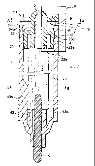
Fig. 1 is a longitudinal section view of a first embodiment
of a writing implement according to the invention;
Fig. 2 is a section view taken along the arrow line A-A
shown in Fig. 1;
Fig. 3 is a section view taken along the arrow line B-B
shown in Fig. l;
Fig. 4 is an enlarged view of a portion P shown in Fig.
l;
Fig. 5 is a perspective view of a tail plug shown in Fig.
l;
Fig. 6 is an enlarged view of the portion P of the rear
end portion of the writing implement shown in Fig. l;
Fig. 7 is a longitudinal section view of the main portions
of a second embodiment of a writing implement according to the
invention; and
Fig. 8 is an enlarged view of the front end portion of
the writing implement shown in Fig. 7.
DETAILED DESCRIPTION OF THE PREFERRED EMBODIMENT
Now, description will be given below of the preferred
embodiments of a writing implement according to the invention
with reference to the accompanying drawings. Figs. 1 to 6
respectively show a first embodiment of a writing implement
13
CA 02321333 2000-09-28
according to the invention. Figs . 7 and 8 show a second embodiment
of a writing implement according to the invention.
[First Embodiment]
Now, description will be given below of the first embodiment
(see Figs. 1 to 6).
(Summary of the structure of the first embodiment)
A writing implement 1 comprises a shaft barrel 4 and a
tail plug 2. The shaft barrel 4 includes an ink storing body
7 stored in an interior portion thereof and a pen point 8 mounted
on a front end portion thereof. The tail plug 2 is removably
mounted on an opening formed at a rear end (hereinafter referred
to "rear end opening") of the shaft barrel 4.
(Shaft barrel)
The shaft barrel 4 can be formed of synthetic resin (for
example, polypropylene) by injection molding. The front end
portion of the shaft barrel 4 is reduced in diameter in a tapered
manner, while the pen point 8 is held in the tapered front end
portion of the shaft barrel 4. Also, the shaft barrel 4 has
a tubular portion 43 which is provided on an inner surface of
the front end portion of the shaft barrel 4 and encloses the
outer periphery of the pen point 8. The tubular portion 43
is formed integral with the inner surface of the shaft barrel
4 and projects therefrom in the axial direction of the shaft
barrel 4. A rear end portion of the tubular portion 43 and
a front end portion of the ink storing body 7 are abutted on
each other in the axial direction of the shaft barrel 4 . Further,
in the rear end portion of the tubular portion 43, there is
14
CA 02321333 2000-09-28
formed a notch 43a for ventilation.
Also, the shaft barrel 4 has a plurality of (specifically,
three) support ribs 43b which are provided on the rear portion
of the tubular portion 43. The support ribs 43b are formed
integral with the shaft barrel 4 and extend in the axial direction
of the shaft barrel 4. The outer peripheral surface of the
front end portion of the ink storing body 7 is pressure contacted
with and supported by the support ribs 43b in the diameter direction
of the ink storing body 7.
The ink storing body 7 is composed of a worked body of
synthetic resin fibers ( for example, a bundled body of polyester
fibers with its outer periphery coated by a film, or a worked
body of thermally welded polyester fibers or a resin worked
body). Ink is impregnated into the interior portion of the
ink storing body 7. The pen point 8 is a bar-shaped resin worked
body of synthetic resin fibers (for example, acrylic fibers
or polyester fibers). The rear end portion of the pen point
8 is stuck into and connected to the front end portion of the
ink storing body 7.
(Tail plug)
The tail plug 2 can be formed of synthetic resin ( for example,
polypropylene) by injection molding. The tail plug 2 comprises
a bottomed, cylinder-shaped connecting portion 22, a bottomed,
cylinder-shaped fitting tubular portion 23 and a disk-shaped
- 25 flange portion 21. The fitting tubular portion 23 is formed
so as to be integral and continuous with the outer peripheral
surface of the central portion of the connecting portion 22.
CA 02321333 2000-09-28
The flange portion 21 is formed so as to be integral and continuous
with the outer peripheral surface of the rear portion of the
connecting portion 22. The front portion of the connecting
portion 22 includes a notch for ventilation 22a as well as it
touches and supports the rear end portion of the ink storing
body 7 in the axial direction thereof.
(Forcibly opening groove)
In a state where the tail plug 2 is mounted on the rear
end opening of the shaft barrel 4, the outer periphery of the
fitting tubular portion 23 is fitted with the inner surface
of the rear end opening of the shaft barrel 4. At the same
time, between the front surface of the flange portion 21 and
the rear end portion of the shaft barrel 4, there is formed
a forcibly opening groove 5 which opens outwardly in the diameter
direction thereof. The axial-direction width dimension of the
groove 5 may be preferably of 2 mm or less so that an ordinary
coin (for example, a ten-yen coin, a hundred-yen coin, and a
five-hundred-yen coin) can be used as a tool 9. Also, in order
to be able to further facilitate the removal of the tail plug
2, the diameter-direction depth dimension of the groove S may
be preferably of 3 mm or more inwardly in the diameter direction
thereof from the outer peripheral surface of the rear end opening
of the shaft barrel 4.
(Airtight fitting portion)
The fitting tubular portion 23 has an annular projection
23a which is provided on the outer peripheral surface of the
fitting tubular portion 23 . The annular projection 23a is formed
16
CA 02321333 2000-09-28
integral with the fitting tubular portion 23 and projects
therefrom. The shaft barrel 4 has an annular projection 41
which is formed integral with the inner peripheral surface of
the rear end opening of the shaft barrel 4. When the tail plug
2 is mounted on the rear end portion of the shaft barrel 4,
the annular projection 23a passes over the annular projection
41, so as to be fitted with the annular projection 41. Further,
the fitting tubular portion 23 has an annular smooth surface
23b which is provided on the outer peripheral surface of the
portion of the fitting tubular portion 23 that is situated in
the rear of the annular projection 23a. The shaft barrel 4
has an annular smooth surface 42 which is formed in the rear
of the annular projection 41 on the inner peripheral surface
of the rear end opening of the shaft barrel 4. The annular
smooth surface 23b is pressure contacted and fitted with the
annular smooth surface 42 . That is, between the outer peripheral
surface of the fitting tubular portion 23 and the inner peripheral
surface of the rear end opening of the shaft barrel 4, there
is formed an airtight fitting portion which consists of the
pass-overfittingportion and pressure-contact fittingportion.
The fitted state of the airtight fitting portion (that is,
the pass-over fitting portion and pressure-contact fitting
portion) can be removed by a forcibly opening operation.
(Reinforcing rib)
The tail plug 2 also has a plurality of (here, four)
plate-shaped reinforcing ribs 24 which provided on the
diameter-direction outer peripheral surface of the portion of
17
CA 02321333 2000-09-28
the connectingportion 22 between the front surface (back surface)
of the flange portion 21 and the bottom wall of the fitting
tubular portion 23 (that is, the rear end portion of the fitting
tubular portion 23). The plate-shaped reinforcing ribs 24 are
radially formed integral with the present outer peripheral
surface. The flange portion 21 and the bottom wall of fitting
tubular portion 23 can be connected together by the reinforcing
ribs 24, which makes it possible to prevent the flange portion
21 from being unstable in the forcibly opening operation.
Each of the reinforcing ribs 24 includes, in the rear end
portion thereof, a stepped portion 24a having an outside diameter
larger than the inside diameter of the rear end opening of the
shaft barrel 4. Specifically, when the tail plug 2 is mounted
on the rear end opening of the shaft barrel 4, the stepped portion
24a is abutted on the rear end portion of the shaft barrel 4.
Namely, the groove S can be positively formed so as to have
a width dimension which allows the tool 9 such as a coin to
be inserted into the groove 5. Also, the portion of the
reinforcing rib 24 that is located in front of the stepped portion
24a is kept away from contact with the inner surface of the
rear end opening of the shaft barrel 4 and is stored into the
interior portion of the rear end opening of the shaft barrel
4.
The distance between the flange portion 21 and the bottom
wall of the fitting tubular portion 23 (that is, the
axial-direction length of the reinforcing rib 24 ) is set larger
than the width dimension of the groove 5 (that is, the
18
CA 02321333 2000-09-28
axial-direction length of the stepped portion 24a) . Due to
this distance setting, there can be formed a space 6 which provides
an escape space for the tail plug 2 with respect to the tool
9 in the forcibly opening operation. This makes it possible
to prevent the front surface of the inner end portion of the
tool 9 from being abutted on the bottom wall of the fitting
tubular portion 23 of the tail plug 2. Therefore the shaft
barrel 4 and tail plug 2 can be separated greatly from each
other simply by the forcibly opening operation of the tool 9.
(Second Embodiment)
Now, description. will be given below of a second embodiment
of a writing implement according to the invention. (see Figs.
7 and 8).
(Summary of the structure of the second embodiment)
A writing implement 1 comprises a shaft barrel 4 (which,
similarly to the first embodiment, is an inj ection-molded body
of synthetic resin) and a pen point hold body 3. The shaft
barrel 4 stores an ink storing body 7 (which, similarly to the
first embodiment, is a worked body of synthetic resin fibers)
in the interior portion thereof. The pen point hold body 3
is removably mounted on an opening formed at the front end
(hereinafter referred to "front end opening") of the shaft
barrel 4 and includes a pen point 8 (which, similarly to the
first embodiment, is a bar-shaped resin worked body of synthetic
resin).
(Pen point hold body)
The pen point hold body 3 can be formed of synthetic resin
19
CA 02321333 2000-09-28
(for example, polypropylene) by injection molding. The pen
point hold body 3 comprises a cylindrical-shaped connecting
portion 32, a disk-shaped flange portion 31 and a bottomed,
cylindrical-shaped fitting tubular portion 33. The connecting
portion 32 holds the outer,surface of the pen point 8. The
flange portion 31 is disposed on the outer peripheral surface
of the front portion of the connecting portion 32 in such a
manner that it is formed so as to be integral and continuous
with the present outer peripheral surface. The fitting tubular
portion 33 is disposed on the outer peripheral surface of the
rear end portion of the connecting portion 32 in such a manner
that it is formed so as to be integral and continuous with the
present outer peripheral surface . The rear end portion of the
connecting portion 32 not only includes a notch 32a for ventilation
but also can be abutted on the front end portion of the ink
storing body 7 in the axial direction thereof to thereby support
the same.
(Forcibly opening groove)
In a state where the pen point hold body 3 is mounted on
the front end opening of the shaft barrel 4, the outer periphery
of the fitting tubular portion 33 is fitted with the inner surface
of the front end opening of the shaft barrel 4. At the same
time, between the rear surface of the flange portion 31 and
the front end portion of the shaft barrel 4, there is formed
a forcibly opening groove 5' which opens outwardly in the diameter
direction thereof. The width dimension of the groove 5' may
be preferably of 2 mm or less so that an ordinary coin (for
CA 02321333 2000-09-28
example, a ten-yen coin, a hundred-yen coin, and a
five-hundred-yen coin) can be used as a tool 9. Also, in order
to be able to further facilitate the removal of the pen point
hold body 3, the diameter-direction depth dimension of the groove
5' may be preferably of 3 mm or more inwardly in the diameter
direction thereof from the outer peripheral surface of the front
end opening of the shaft barrel 4.
(Airtight fitting portion)
The fitting tubular portion 33 has an annular projection
33a which is provided on the outer peripheral surface of the
fitting tubular portion 33 . The annular proj ection 33a is formed
integral with the fitting tubular portion 33 and projects
therefrom. The shaft barrel 4 has an annular projection 41
which is formed integral with the inner peripheral surface of
the front end opening of the shaft barrel 4. When the pen point
hold body 3 is mounted on the front end portion of the shaft
barrel 4, the annular projection 33a passes over the annular
projection 41, so as to be fitted with the annular projection
41. Further, the pen point hold body 3 has an annular smooth
surface 33b which is provided on the outer peripheral surface
of the portion of the fitting tubular portion 33 that is situated
in the front of the annular projection 33a. The shaft barrel
4 has an annular smooth surface 42 which is formed in front
of the annular projection 41 on the inner peripheral surface
of the front end opening of the shaft barrel 4. The annular
smooth surface 33b is pressure contacted and fitted with the
annular smooth surface 42: That is, similarly to the first
21
CA 02321333 2000-09-28
embodiment, between the outer peripheral surface of the fitting
tubular portion 33 and the inner peripheral surface of the front
end opening of the shaft barrel 4, there is formed an airtight
fitting portion which consists of the pass-over fitting portion
and pressure-contact fitting portion. The fitted state of the
airtight fitting portion (that is, the pass-over fitting portion
and pressure-contact fitting portion) can be removedbya forcibly
opening operation.
(Reinforcing rib)
The pen point hold body 3, similarly to the first embodiment,
has a plurality of (here, four) plate-shaped reinforcing ribs
34 which are provided on the diameter-direction outer peripheral
surface of the portion of the connecting portion 32 between
the rear surface (back surface) of the flange portion 31 and
the bottom wall of the fitting tubular portion 33 (that is,
the front end portion of the fitting tubular portion 33). The
plate-shaped reinforcing ribs 34 are radially formed integral
with the present outer peripheral surface. The flange portion
31 and the bottom wall of the fitting tubular portion 33 can
be connected together by the reinforcing ribs 34, which makes
it possible to prevent the flange portion 31 from being unstable
in the forcibly opening operation.
Each of the reinforcing ribs 34 includes, in the front
end portion thereof, a stepped portion 34a having an outside
diameter larger than the inside diameter of the front end opening
of the shaft barrel 4. Specifically, when the pen point hold
body 3 is mounted on the front end opening of the shaft barrel
22
CA 02321333 2000-09-28
4, the stepped portion 34a is abutted on the front end portion
of the shaft barrel 4. Namely, the groove 5' can be positively
formed so as to have a width dimension which allows the tool
9 such as a coin to be inserted into the groove 5'. Also, the
portion of the reinforcing rib 34 that is located in the rear
of the stepped portion 34a is kept away from contact with the
inner surface of the front end opening of the shaft barrel 4
and is stored into the interior portion of the front end opening
of the shaft barrel 4.
The distance between the flange portion 31 and the bottom
wall of the fitting tubular portion 33 (that is, the
axial-direction length of the reinforcing rib 34 ) is set larger
than the width dimension of the groove 5' (that is, the
axial-direction length of the stepped portion 34a). Due to
such distance setting, there can be formed a space 6' which
provides an escape space for the pen point hold body 3 with
respect to the tool 9 in the forcibly opening operation. This
makes it possible to prevent the rear surface of the inner end
portion of the tool 9 from being abutted on the bottom wall
of the fitting tubular portion 33 of the pen point hold body
3, and therefore the shaft barrel 4 and pen point hold body
3 can be separated greatly from each other simply by the forcibly
opening operation of the tool 9.
(Others)
In the writing implement 1 according to the first embodiment,
the tail plug 2 may be replaced with the pen point hold body
3 according to the second embodiment. Also, writing implement
23
CA 02321333 2000-09-28
1 according to the second embodiment, may have another pen point
hold body removably mounted on the opening formed at the rear
end of the shaft barrel. That is, the writing implement 1 may
be a two-head-type writing implement which includes two pen
points in the two ends thereof.
As the above-mentioned pen point 8, there can be used other
bodies than the fiber worked body; for example, a pen body formed
of synthetic resin by extrusion molding, a ball-point pen tip,
a pipe-shaped pen body, a plate-shaped pen body including a
slit in the front end thereof, a writing brush body, and a porous
pen body.
According to the first aspect of the invention, the plug
body can be easily removed from one end portion of the shaft
barrel. At the same time, the flange portion of the plug body
and one end portion of the shaft barrel can be sufficiently
prevented against damage.
According to the second aspect of the invention, there
can be formed the escape space for the plug body with respect
to a tool in a forcibly opening operation. Namely, the back
surface of the tool can be prevented from being abutted on the
end portion of the fitting tubular portion of the plug body,
and the shaft barrel and plug body can be separated greatly
away from each other simply by the forcibly opening operation
of the tool.
According to the third aspect of the invention, in the
forcibly opening operation, the flange portion can be prevented
from being unstable, which makes it possible to remove the plug
24
CA 02321333 2000-09-28
body in a stable manner.
According to the fourth aspect of the invention, the tail
plug can be easily removed from the rear end portion of the
shaft barrel. At the same time, the flange portion of the tail
plug and the rear end portion of the shaft barrel can be
sufficiently prevented against damage.
According to the fifth aspect of the invention, there can
be formed an escape space for the tail plug with respect to
the tool in the forcibly opening operation of the tool . Namely,
the front surface of the tool can be prevented from being abutted
on the rear end portion of the fitting tubular portion of the
tail plug, and the shaft barrel and tail plug can be separated
greatly away from each other simply by the forcibly opening
operation of the tool.
According to the sixth aspect of the invention, in the
forcibly opening operation, the flange portion can be prevented
from being unstable, which makes it possible to remove the tail
plug in a stable manner.
According to the seventh aspect of the invention, the pen
point hold body can be easily removed from the front end portion
of the shaft barrel. At the same time, the flange portion of
the pen point hold body and the front end portion of the shaft
barrel can be sufficiently prevented against damage.
According to the eighth aspect of the invention, there
can be formed an escape space for the pen point hold body with
respect to the tool in the forcibly opening operation of the
tool. Namely, the rear surface of the tool can be prevented
CA 02321333 2000-09-28
from being abutted on the front end portion of the fitting tubular
portion of the pen point hold body, and the shaft barrel and
pen point hold body can be separated greatly away from each
other simply by the forcibly opening operation of the tool.
According to the ninth aspect of the invention, in the
forcibly opening operation, the flange portion can be prevented
from being unstable, which makes it possible to remove the pen
point hold body in a stable manner.
26