Note: Descriptions are shown in the official language in which they were submitted.
CA 02321402 2000-09-28
-1-
LAMINATED PANEL
The present invention relates to a laminated panel
comprising at least two sheet members, and in particular to a
laminated panel for a diaper cover, disposable diaper, sanitary
napkin, urine-absorbent pad and the like.
Japanese Patent Application Disclosure No. 1996-196559
discloses a disposable diaper comprising a liquid-permeable
topsheet, a liquid-impermeable backsheet and a liquid-
absorbent core interposed between the topsheet and the
backsheet. The core formed of a liquid retaining layer and a
fiber assembled layer is covered with tissue paper (water-
permeable sheet ) , and the core and the tissue paper are joined
by means of hotmelt adhesive substantially in the entire area
of the surface at which the core and the tissue paper overlap
with each other. The application pattern of the adhesive
includes a dot-like application pattern formed with a plurality
of straight continuous dot-like lines extending in one
direction; a vertical stripe application pattern formed with
a plurality of straight lines extending in one direction; a
grid-like application pattern formed with straight lines
extending while intersecting with each other; and a spiral
application pattern formed with a plurality of curved lines
CA 02321402 2000-09-28
-2-
extending while intersecting with themselves.
The adhesive applied in the dot-like pattern or the
vertical stripe pattern can prevent delamination between the
core and the tissue paper with respect to the direction
perpendicular to the direction in which the adhesive extends .
However, with respect to the direction in which the adhesive
extends, delamination between the core and the tissue paper is
prevented just at points, so that the core and the tissue paper
may easily be delaminated in the direction in which the adhesive
extends.
In order to reinforce the adhesive strength, it is
preferable to apply the adhesive in the grid-like pattern or
in the spiral pattern. However, at the points where the
adhesive intersects with other adhesive or itself, the adhesive
is applied one upon another, resulting that the application
amount of the adhesive is increased compared to the portion
where the adhesive does not intersect with other adhesive or
itself. At the intersecting points, the adhesive havingsoaked
into the tissue paper will close fiber gaps of the tissue paper
over a wide area. Accordingly, if the number of intersecting
points is too large, the adhesive will sometimes prevent the
liquid permeability of the tissue paper.
CA 02321402 2000-09-28
-3-
It is an object of the invention to provide a laminated
panel in which an adhesive is applied so that delamination is
unlikely to occur in a direction in which the adhesive extends
as well as in a direction intersecting the direction comprising
the adhesive extends, and liquid permeability possessed by
sheet members will not be prevented.
A laminated panel of the present invention comprises at
least two sheet members overlapped with and joined to each other
by means of adhesive applied on at least one of inner surfaces
of the sheet members, wherein the adhesive forms a plurality
of separated adhesive lines extending in one direction while
being bent; the number of times in which one of the adhesive
lines repeats bending is in the range of 50 to 200 per 1 m of
the sheet member; the number of times in which one of the adhesive
lines intersects is in the range of 0 to 200 per 1 m of the sheet
member.
In the present invention "bending" or "bent" involves the
case where the adhesive line extends in a zigzag pattern while
being bent; the case where the adhesive line extends in a wave
shape while rising and falling; and the case where the adhesive
line extends in a square wave shape while picturing bumps and
dips.
In the laminated panel constituting the body fluid
CA 02321402 2000-09-28
-4-
disposal article, since the adhesive does not prevent the liquid
permeability of the topsheet and the water permeability of the
tissue paper, body fluids can be smoothly transferred from the
topsheet to the tissue paper, and then from the tissue paper
to the core, with the result that it is possible to sufficiently
utilize the liquid absorptivity possessed by the core.
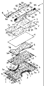
Fig. 1 is an exploded perspective view of a disposable
diaper;
Fig. 2 is a partially cutaway perspective view of a diaper
in assembled state;
Fig. 3 is a section view along line A-A of Fig. 2; and
Fig. 4 is a view showing adhesive lines of an adhesive
applied on a sheet member.
In the following, with reference to the accompanied
drawings, a laminated panel according to the present invention
will be described in more detail by taking a disposable diaper
as an example.
Fig. 1 is an exploded perspective view of a disposable
diaper 1. The diaper 1 comprises a liquid-permeable topsheet
2 of hourglass shape, a liquid-impermeable backsheet 3 of
hourglass shape, a pair of tissue papers 4 (liquid-permeable
CA 02321402 2000-09-28
-5-
sheets) interposed between the topsheet 2 and the backsheet 3,
a liquid-absorbent core 5 of hourglass shape interposed between
the tissue papers 4, and a pair of liquid-barrier sheets 6
opposed to and spaced from each other and extending in the
vertical direction.
The diaper 1 has, in addition to the above constituents
of the diaper 1, a pair of leg encirclable elastic members 7
opposed to and spaced from each other and extending in the
vertical direction, a pair of waist encirclable elastic members
8 opposed to and spaced from each other and extending in the
horizontal direction, a tape fastener 9 and a target tape 10
serving as a receiving area of the tape fastener 9. In the
drawing, the barrier sheets 6 are disposed at the top, then the
topsheet 2, the tissue paper 4, the core 5, the tissue paper
4, the backsheet 3 and the target tape 10 are disposed in this
order toward the bottom of the drawing.
The topsheet 2 and the backsheet 3 have both side edges
2a and 3a, the respective both side edges opposed to each other
and extending in the vertical direction, and front and back end
edges 2b, 2c and 3b, 3c, the respective front and back end edges
opposed to each other and extending in the horizontal direction.
The respective both side edges 2a and 3a of the topsheet 2 and
the backsheet 3 are angularly recessed at their center portions
CA 02321402 2000-09-28
-6-
toward a vertical center line Y separating the topsheet 2 and
the backsheet 3 into two halves in the horizontal direction,
and the recesses are large on the side of the front end edges
2b and 3b with respect to a horizontal center line X separating
the topsheet 2 and the backsheet 3 into two halves in the vertical
direction, while the recesses are smaller on the side of the
back end edges 2c and 3c compared to the side of the front end
edges 2b and 3b. Therefore, the topsheet 2 and the backsheet
3 are formed larger in size on the side of the back end edges
2c and 3c than the side of the front end edges 2b and 3b.
On the inner surface of the backsheet 3, the pair of leg
encirclable elastic members 7 which are elastically extensible
along the both side edges 3a of the backsheet 3 are arranged,
and the pair of film-like waist encirclable elastic members 8
which are elastically extensible along the front and back end
edges 3b, 3c of the backsheet 3 are arranged in elongated state.
On the inner surface of the backsheet 3 on the side of the back
end edge 3c, a proximal end of the tape fastener 9 extending
inwardly in the horizontal direction from the both side edges
3a of the backsheet 3 is arranged.
The tissue paper 4 is of a rectangular shape having an
area smaller than those of the topsheet 2 and the backsheet 3
but larger than that of the core 5.
CA 02321402 2000-09-28
The barrier sheet 6 has free side edge portions 6a
extending in the vertical direction, base side edge portions
6b opposed to the free side edge portions 6a and extending in
the vertical direction, outside portions 6c protruding
outwardly in the horizontal direction from the base side edge
portions 6b and extending in the vertical direction, and both
end portions 6d in the vertical direction located at the front
and back end edges 2b, 2c and 3b, 3c of the topsheet 2 and the
backsheet 3. On the free side edge portions 6a of the barrier
sheets 6, elastic extensible members 11 are mounted in elongated
state while being covered with the free side edge portions 6a.
The outside portions 6c of the barrier sheets 6 are angularly
recessed at their center portions inwardly in the horizontal
direction.
On the inner surfaces of the topsheet 2 and the backsheet
3 opposed to each other, adhesives B1 and B2 are applied for
joining the topsheet 2 and the backsheet 3 and joining the
topsheet 2 and the backsheet 3 to the tissue paper 4. On the
inner surface of the tissue paper 4 in the lower portion of the
drawing, an adhesive B3 is applied for adhering the tissue paper
4 and the core 5. on the inner surfaces of the barrier sheets
6 at the outside portions 6c and on the outer surfaces of the
barrier sheets 6 at the both end portions 6d, adhesives B4 are
CA 02321402 2000-09-28
_g_
applied for joining the outside portions 6c of the barrier
sheets 6 to the topsheet 2 and the backsheet 3, and the adhesives
B4 are applied for joining the both end portions 6d of the barrier
sheets 6 to the outside portions 6c of the barrier sheet 6. On
the inner surface of the target tape 10, an adhesive B5 is applied
for joined the target tape 10 to the outer surface of the
backsheet 3. On the proximal end of the tape fastener 9 is
applied an adhesive ( not shown ) , so that it is adhered to the
backsheet 3.
The adhesives B1 to B5 form a plurality of separated
adhesive lines L extending in the vertical direction of the
diaper 1 while raising and falling in wave shapes. In the
adhesive lines L, adjacent adhesive lines L extend so as not
to intersect with each other, and intersecting points 30 where
a certain adhesive line L intersects with itself are dispersed.
The adhesives B1 to B5 are applied on the topsheet 2, the
backsheet 3, the tissue paper 4, the barrier sheet 6 and the
target tape 10 substantially uniformly so as to eliminate
unevenness.
In the drawing, by covering the entire core 5 with the
tissue paper 4, the core 5 and the tissue paper 4 are joined
to each other by means of the adhesive B3 applied on the tissue
paper 4. The tissue paper 4 and the tissue paper 4 are joined
CA 02321402 2000-09-28
-9-
to each other at the part extending outwardly in the
circumferential direction of the core 5 from the periphery of
the core 5. By overlaying the topsheet 2 and the backsheet 3
on the outer surfaces of the respective tissue papers 4, the
tissue papers 4 are joined to the topsheet 2 and the backsheet
3 by means of the adhesives B1 and B2 applied on the topsheet
2 and the backsheet 3, while the topsheet 2 and the backsheet
3 are joined to each other at the both side edges 2a and 3a and
the front and back end edges 2b, 2c and 3b, 3c of the topsheet
2 and the backsheet 3.
By overlaying the outside portions 6c of the barrier
sheets 6 on the both side edges 2a and 3a of the topsheet 2 and
the backsheet 3, and overlaying the both end portions 6d of the
barrier sheets 6 on the outside portions 6c of the barrier sheets
6 while being fallen down to the outside of the diaper 1, the
outside portions 6c of the barrier sheets 6 are joined to the
both side edges 2a and 3a of the topsheet 2 and the backsheet
3 via the adhesives B4 applied on the outside portions 6c of
the barrier sheets 6, and the both end portions 6d of the barrier
sheets 6 are joined to the outside portions 6c of the barrier
sheets 6 by means of the adhesives B4 applied on the both end
portions 6d of the barrier sheets 6. By overlaying the inner
surface of the target tape 10 on the outer surface of the
CA 02321402 2000-09-28
-10-
backsheet 3 at the front end edge 3a, the target tape 10 is joined
to the backsheet 3 by means of the adhesive B5 applied on the
target tape 10.
Fig. 2 is a partially cutaway perspective view of the
diaper 1 in a state that the exploded perspective view of Fig.
1 is assembled, and Fig. 3 is a section view taken in the
direction of the arrows along line A-A. The diaper 1 has a front
waist region 20, a back waist region 22 and a crotch region 21
located between the front waist region 20 and the back waist
region 22, and further has a pair of side flaps 12 opposed to
each other and extending in the vertical direction, the side
flaps 12 being recessed inwardly in the horizontal direction
of the diaper 1 in the crotch region 21, and a pair of end flaps
13 opposed to each other and extending in the horizontal
direction.
The side flaps 12 are formed of the both side edges 2a
and 3a of the topsheet 2 and the backsheet 3, and the outside
portions 6c of the barrier sheets 6. In the side flaps 12, the
both side edges 2a of the topsheet 2 extend outwardly in the
horizontal direction from both side edges 5a of the core 5, and
the both side edges 3a of the backsheet 3 and the outside portions
6c of the barrier sheets 6 extend outwardly in the horizontal
direction from the both side edges 2a of the topsheet 2. In
CA 02321402 2000-09-28
-11-
the side flaps 12, the both side edges 2a and 3a of the topsheet
2 and the backsheet 3 are joined by means of the adhesives B1
and B2, and the both side edges 2a and 3a of the topsheet 2 and
the backsheet 3 and the outside portions 6c of the barrier sheets
6 are joined by means of the adhesives B2 and B4. In the side
flaps 12, the leg encirclable elastic members 7 are joined to
the inner surface of the backsheet 3 while being interposed
between the tissue paper 4 and the backsheet 3.
The end flaps 13 are formed of the front and back end edges
2b, 2c and 3b, 3c of the topsheet 2 and the backsheet 3, and
part of the outside portions 6c and the both end portions 6d
of the barrier sheets 6. In the end flaps 13, the front and
back end edges 2b, 2c and 3b, 3c of the topsheet 2 and the
backsheet 3 are joined and the front and back end edges 2b, 2c
of the topsheet 2 are joined to part of the outside portions
6c of the barrier sheets 6. In the end flaps 13, the both end
portions 6d of the barrier sheets 6 are joined to the outside
portions 6c of the barrier sheets 6, and the waist encirclable
elastic members 8 are joined to the inner surfaces of the
topsheet 2 and the backsheet 3 while being interposed between
the topsheet 2 and the backsheet 3.
In the back waist region 22 of the diaper 1, the tape
fastener 9 is bent so as to extend inwardly in the horizontal
CA 02321402 2000-09-28
-12-
direction of the diaper 1, the tape fastener 9 being removably
adhered to the outer surface of the topsheet 2 by means of the
adhes ive ( not shown ) applied on the free end portion of the tape
fastener 9. In the diaper 1, the side traps 12, the end traps
13 and the free side edge portions 6a of the barrier sheets 6
are formed with gathers under the condition that the elastic
members 7, 8 and 11 are released from elongated state and the
elastic members 7, 8 and 11 are in contracted state. In the
diaper 1, the elastic members 11 attached to the free side edge
portions 6a of the barrier sheets 6 are contracted, and the free
side edge portions 6a of the barrier sheets 6 stand in an upward
direction of the diaper 1.
As shown in Fig. 3, in the diaper 1, the adhesives B1 to
B4 applied on the backsheet 3, the tissue papers 4 and the barrier
sheets 6 do not appear such that they are dispersed in the
horizontal direction of the diaper 1, but the adhesives B1 to
B4 extending with being bent appear such that they are applied
on generally whole areas of the topsheet 2, the backsheet 3,
the tissue papers 4 and the barrier sheets 6 in the horizontal
direction of the diaper 1. Therefore, the topsheet 2, the
backsheet 3, the tissue papers 4 and the barrier sheets 6 are
unlikely to delaminate not only in the horizontal direction of
the diaper 1 but also in the vertical direction of the diaper
CA 02321402 2000-09-28
-13-
1.
In the side flaps 12, since the both side edges 3a of the
backsheet 3 and the outside portions 6c of the barrier sheets
6 extend outwardly in the horizontal direction than the both
side edges 2a of the topsheet 2, even when body fluids soak into
the both side edges 2a of the topsheet 2, they cannot soak into
the backsheet 3 and the barrier sheets 6, so that it is possible
to prevent the body fluids from leaking from the side flaps 12.
Fig. 4 shows adhesive lines L of the adhesives B1 to B5
applied on any one of the sheet members of the topsheet 2, the
backsheet 3, the tissue papers 4, the barrier sheets 6 and the
target tape 10, and the adhesives B1 to B5 are partially omitted
in the drawing. The number of times in which one of the adhesive
lines L repeats bending is in the range of 50 to 200, preferably
in the range of 100 to 150 per 1 m of vertical dimension of the
sheet member, and the number of times in which one of the adhesive
lines L intersects is in the range of 0 to 200 per 1 m of vertical
dimension of the sheet member. The number of times in which
the adhesive line L repeats bending is counted by defining the
part from the apex of the top to the apex of the neighboring
top as one. The situation "the adhesive line L intersects" also
involves the case where the adhesive line L contacts with itself,
in addition to the case where the adhesive line L intersects
CA 02321402 2000-09-28
-14-
with itself.
If the number of times in which the adhesive line L repeats
bending is less than 50, the interval between neighboring tops
becomes large and the adhesive line approaches a straight line,
resulting that adhesive strength of the adhesive in the
direction in which the adhesive line L extends becomes weak.
Contrarily, if the number of times in which the adhesive line
L repeats bending is more than 200, there is a possibility that
the number of times in which the adhesive line L intersects with
itself exceeds 200.
At the points 30 where the adhesive line L intersects with
itself, the adhesives B1 and B3 having soaked into the topsheet
2 and the tissue papers 4 close fiber gaps of the topsheet 2
and the tissue paper 4 over wide areas . Therefore, if the number
of times in which the adhesive line L intersects with itself
is more than 200, the liquid permeability of the topsheet 2 and
the tissue paper 4 will be prevented. As a result, because the
body fluids can not smoothly move from the topsheet 2 to the
tissue paper 4, and then from the tissue paper 4 to the core
5, it is impossible to sufficiently utilize the liquid
absorptivity of the core 5. Furthermore, even if the adhesive
H3 does not soak into the tissue paper 4, the adhesive B3 extends
on the inner surface of the tissue paper 4 to cover the surface
CA 02321402 2000-09-28
-15-
of the core 5 at the points 30 where the adhesive line L
intersects with itself, resulting that the liquid absorptivity
of the core 5 will sometimes be prevented.
Preferably, in the case of adhering the topsheet 2 and
the backsheet 3, the amounts of adhesives B1 and B2 to be applied
on the topsheet 2 and the backsheet 3 are in the range of 3 to
8 g per 1 m~ of area of the topsheet 2 and the backsheet 3; in
the case of adhering the core 5 and the tissue paper 4, the amount
of adhesive B3 to be applied on the tissue paper 4 is in the
range of 0 . 8 to 5 g per 1 mZ of area of the tissue paper 4 ; in
the case of adhering the barrier sheets 6 to the topsheet 2 and
the backsheet 3, the amount of adhesives B4 to be applied on
the barrier sheets 6 is in the range of 3 to 8 g per 1 mZ of
area of the barrier sheet 6; and in the case of joining the
topsheet 2 and the backsheet 3 to the elastic members 7 and 8,
the amounts of adhesives B1 and B2 to be applied on the topsheet
2 and the backsheet 3 are in the range of 8 to 15 g per 1 mZ
of area of the topsheet 2 and the backsheet 3.
If the application amounts of the adhesives B1 to B5 are
les s than the above ranges , adhes ive strength will become weak,
so that the topsheet 2, the backsheet 3, the tissue papers 4,
the barrier sheets 6, the core 5 and the elastic members 7 and
8 tend to easily delaminate in the adhering regions. If the
CA 02321402 2000-09-28
-16-
application amounts of the adhesives B1 and B3 are more than
the above ranges, the adhesives B1 and B3 having soaked into
the topsheet 2 and the tissue paper 4 will close fiber gaps of
the topsheet 2 and the tissue paper 4 over wide areas, resulting
that the liquid permeability of the topsheet 2 and the water
permeability of the tissue paper 4 are prevented, though this
phenomenon depends on the basis weight and the fineness of the
fiber forming the topsheet 2 or the tissue paper 4.
It is preferable that viscosity numbers of the adhesives
B1 to B5 are in the range of 4000 to 5500 cP. If the viscosity
numbers of the adhesiv2s B1 and B3 are less than 4000 cP, the
adhesives B1 and B3 are likely to soak into the topsheet 2 and
the tissue paper 4, and likely to expand inside of the fibers
of the topsheet 2 and the tissue paper 4. Contrarily, if the
viscosity numbers of the adhesives B1 to B5 are larger than 5500
cP, there is a possibility that the adhesives B1 to B5 solidify
in clusters.
For the topsheet 2, a hydrophobic nonwoven fabric treated
with a hydrophilic agent or a hydrophilic nonwoven fabric formed
of fibers into which a hydrophilic agent is kneaded is used.
For the backsheet 3 and the barrier sheet 6, a synthetic resin
film or a laminated sheet of a synthetic resin film and a
hydrophobic nonwoven fabric, and preferably a breathable
CA 02321402 2000-09-28
- 17-
liquid-impermeable sheet is used. As the nonwoven fabric, an
air through nonwoven fabric, a point bonded nonwoven fabric,
a span bonded nonwoven fabric, a span lace nonwoven fabric, a
melt blown nonwoven fabric and the like can be used.
The core 5 is formed of a mixture of fluff pulp and high
adsorbent polymer particles to which fibers are appropriately
added for maintaining the shape of the absorber, and compressed
into a predetermined thickness. For the liquid-permeable
sheet covering the core 5, liquid-permeable nonwoven fabrics
having a basis weight in the range of 5 to 10 g/mZ may be used
besides the tissue paper 4.
For the elastic members 7, 8 and 11, elastomers such as
synthetic rubber and natural rubber or materials in which such
elastomers are adhered in elongated state to nonwoven fabrics
may be used.
For the adhesives B1 to B5, block rubber hotmelt adhesives,
olefinic hotmelt adhesives may be used. The adhesives B1 and
B2 may be applied on either one of the topsheet 2 and the
backsheet 3, besides the case where the adhesives B1 and B2 are
applied on both of the topsheet 2 and the backsheet 3.
Furthermore, the adhesives B1 to B5 may be applied in a dotted
pattern. As for the barrier sheet 6, the both end portions 6c
of the barrier sheets 6 may be adhered to the front and back
CA 02321402 2000-09-28
-18-
end edges 2b, 2c of the topsheet 2 in a state that the both end
portions 6c are fallen down to the inside of the diaper 1. In
the case where the barrier sheets 6 are joined in a condition
that the both end portions 6c are fallen down to the inside of
the diaper 1, the adhes ives B4 are appl ied on the inner surf aces
of the barrier sheets 6 in the both end portions 6c.
The present invention may be applied to a diaper cover,
sanitary napkin, urine-absorbent pad and the like, or to a
composite sheet for dirt wiping or a composite sheet in which
an extensible sheet is joined in elongated state to a non-
extensible sheet and the like, in addition to the disposable
diaper 1.
According to a laminated panel of the present invention,
since the adhesives are applied on the sheet members so as to
form a plurality of separated adhesive lines extending in one
direction while being bent, it is possible to join the sheet
members with substantially equal adhesivestrength with respect
to both of the direction in which the adhesive extends and the
direction perpendicular to the direction in which the adhesive
extends, so that delamination of the sheet members can be
prevented.
Regarding the adhesive line, since the number of times
in which the adhesive line repeats bending is in the range of
CA 02321402 2000-09-28
-19-
50 to 200 per 1 m of dimension of the sheet member, and the number
of times in which the adhesive line intersects with itself is
in the range of 0 to 200 per 1 m of dimension of the sheet member,
even when the applied adhesive soaks into the sheet member and
fiber gaps of the sheet member are closed, it is possible to
suppress the area in which the fiber gaps are closed to minimum,
so that the liquid permeability and water permeability of the
sheet material will not be prevented.
In the case where the application amount of the adhesive
is in the range of 0. 8 to 8 g per 1 m2 of area of the sheet member,
it is possible to prevent the adhesive having soaked into the
sheet member from closing the fiber gaps of the sheet member
over wide areas while preventing delamination of the sheet
member.