Note: Descriptions are shown in the official language in which they were submitted.
CA 02321711 2007-04-05
29443-6
SPECIFICATION
Combination of Driver Bit arid Screw
TECHNICAL FIELD
The present invention relates to a driver bit and a screw
for use therewith. More particularly, it relates to a
combiriation of a driver bit and a screw fitting the driver bit
which combination effects tight mating of crossed flutes or bit
mate flutes formed in the screw head portion and the driver bit
fitting the flutes and always enables quick positive screwing
and unscrewing by transmission of appropriate torque.
BACKGROUND ART
Conventionally known are the combinations of typical
screws and driver bits as shown in Figs.13 to 16. That is,
Figs.13 and 14 show a conventional screw with crossed flutes;
F i g. 1.5 shows a driver bit for use with the screw with crossed
flutes; and Fig.16 shows the aforementioned screw and driver
bit, mated with each other.
A prior art screw 10 shown in Fig.13 is provided, in a
screw head portion 10a thereof, with crossed flutes 12. The
crossed flutes 12 are provided with constantly inclined flute
nortions 12a, each extending from the end portion towards the
central portion of a screw neck portion 10b. The crossed flutes
12 are also provided, on a bottom portion thereof, with a
1
CA 02321711 2007-04-05
29443--6
substai-itially conical bottom surface 14 inclined gradually.
Incide:Ztally, reference numeral 13 designates tapered sidewall
portions formed between adjacent crossed flutes 12. That is,
the tapered sidewall portions 13 engageably contact with the
blade;oortions of a driver bit, which is described later. In
addition, at the corners adjoining the respective inclined
flute portions 12a, tapered coupling surfaces are
formed which extend from the position of the conical bottom
surface 14 to the opening rim portions of the crossed flutes
in the screw head portion 10a. These tapered coupling
surfaces are also adapted to engageably contact part
of thE: blade portions of the driver bit, which is described
later.
On the other hand, a prior art driver bit 20 shown in Fig. 15
is provided with blade portions 22 to fit the crossed flutes
12 of the aforementioned screw 10. The driver bit 20 is also
provided with extended blade portions 22a each extend so as
to fit the shape of the inclined flute portions 12a that are
formed to orient towards the central portion of the screw neck
portion lOb from the end portions of the aforementioned crossed
flutes 12. Incidentally, reference numeral 23 designates
tapered sidewall portions that are formed on the both sides of
the aforementioned respective blade portions 22 or extended
blade portions 22a. That is, the tapered sidewall portions 23
engageably contact with the tapered sidewall portions 13 formed
2
CA 02321711 2000-08-23
in the crossed flutes 12 of the aforementioned screw 10.
According to the combination of the prior art screw and
driver bit formed as such, when the screw 10 and the driver bit
20 are fit to each other as shown in Fig.16, the blade portions
22 of the driver bit 20 and extended blade portions 22a fit into
the inclined flute portions 12a of the crossed flutes 12,
respectively, as described above. The sidewall portions 23 of
the aforementioned blade portions 22 and extended blade
portions 22a are brought into contact with the tapered sidewall
portions 13 of the crossed flutes 12 of the screw 10. Thus,
rotating the driver bit 20 allows a predetermined torque to be
transmitted to the screw 10. That is, screwing and unscrewing
can be achieved on a desired target object to be screwed.
However, according to the combination of the prior art
screw 10 and the driver bit 20 formed as described above, the
crossed flutes 12 of the screw head portion l0a form constantly
inclined flute portions 12a orienting towards the central
portion of the screw neck portion lOb from the end portions
thereof. On the other hand, for the driver bit 20 corresponding
thereto, the ridge portions of the extended blade portions 22a
fit the shape of the aforementioned inclined flute portions 12a
to fit into the aforementioned crossed flutes 12. Moreover,
the ridge portions of the extended blade portions 22a are made
wider gradually backwards from the distal end portion thereof.
Furthermore, the tapered sidewall portions 23 formed on the
3
CA 02321711 2007-04-05
29443-6
respec:tive blade portions 22 of the driver bit 20 are also
engageably brought into contact with the tapered sidewall
portions 13 formed in the crossed flutes 12 of the screw 10.
Accordingly, since the aforementioned driver bit 20 and the
crossed flutes 12 can be said to be totally in taper contact
with one another, rotating the aforementioned driver bit 20 in
a predetermined direction causes the distal end of the driver
bit 20 to fly outwardly along the inclined surface of the
inclined flute portions 12a of the aforementioned crossed
flutes 12 (shown by an arrow in Fig.16), resulting in the
so-called "come-out phenomenon".
In particular, as shown in Fig.14, the shape of the
crossed flutes of a prior art screw is formed in such a manner
that the respective crossed flutes 12 are made relatively larger
in width than the ridge portions of the extended blade portion.s
22a of the driver bit 20 in order to facilitate mating the distal
end of the driver bit 20 with the crossed flutes. On the other
hand, the area of the tapered sidewall portions 13 and the
tapered coupling surfaces, formed at a boundary portion
or corner portions between adjacent crossed flutes 12, 12, is
relatively small. Accordingly, rotating the aforementioned
driver bit 20 causes a great amount of stress to be loaded on
the aforementioned tapered sidewall port ions 13 andthetapered
coup:Ling surfaces. Thus, as shown in Fig. 14 with
shaded portions 15, great fastening resistance would cause the
4
CA 02321711 2007-04-05
29443-6
r
aforementioned tapered sidewall portions 13 and the tapered
coupling surfaces to be gradually damaged. Therefore,
an increase in the damaged portions (the shaded portions 15)
would make the come-out phenomenon to occur frequently in the
aforenientioned driver bit 20, making it impossible to effect
screwing.
From these points of view, it is necessary to apply thrust
to the driver bit 20 to strongly press the bit against the flute
portions 12a at the time of rotating the driver bit 20 in order
to prevent the come-out phenomenon in the aforementioned driver
bit 20. However, pressing the bit as such would cause screwed
targe-r- objects, particularly such as precision parts, to be
broke:z or damaged although no problem will occur if the target
objects are rigid bodies such as metal.
In addition, the occurrence of the aforementioned
ccme-out phenomenon would cause the distal end portion of the
bit or the blade portions 22 and extended blade portions 22a
to be worn quickly. The wear would cause the aforementioned
come-out phenomenon to occur more frequently, resulting in an
increase of the damage of the screw flutes.
Furthermore, applying an excessive thrust to the
aforementioned driver bit 20 could be useful to prevent the
aforementioned come-out phenomenon. However, this would make
it impossible to transmit precise torque to the screw, and thus
operators would apply different amount of thrust to the driver
5
CA 02321711 2000-08-23
bit 20. Consequently, torque for fastening screws would become
greatly different from operator to operator.
Still furthermore, when tapping screws are screwed into
a target object made of synthetic resin or the like, friction
caused by the thrust would be added to that by the rotation of
the screw. This would cause a great amount of heat to be
produced to such an extent as to reduce the hardness of the
screwed portion of the target object, thereby causing the screw
to become loose or the target object to be damaged.
On the other hand, when screwing is carried out manually,
rotating the driver bit 20 while sufficiently pressing the
driver bit 20 against the screw would require a great amount
of effort of the operator and make the operator exhausted.
In addition, according to the combination of the
aforementioned prior-art screw 10 and the driver bit 20, when
screwing is carried out with a manual tool or an electric tool,
it is difficult to rotate the screw while maintaining the screw
axis and the driver bit axis in proper alignment with each other
at the time of fitting the distal end potion of the bit to the
screw flutes. Therefore, when the screw axis is inclined
relative to the driver bit axis, not only the aforementioned
come-out phenomenon but also damage to the screw flutes will
occur frequently.
Furthermore, at the time of unscrewing, like in the
foregoing, the come-out phenomenon and damage to the screw
6
CA 02321711 2000-08-23
flutes will be likely to occur. However, in this case, it will
become impossible to remove the screws, thus resulting in such
a situation as to break part of the target object to be unscrewed.
In particular, when dust particles clog the screw flutes, the
aforementioned situation occurs more frequently.
From these points of view, the present applicant
previously suggested the combination of screws and driver bits
which can effectively prevent the come-out phenomenon of the
driver bit and damage to screws as occurred conventionally
(Japanese Patent Laid-Open Publication No.Hei 8-145024 and
No.Hei 9-177743). In addition, the combination can always
provide appropriate and quick screwing and thus make it possible
to significantly improve the efficiency of screwing even when
damage has occurred to the bit mate flutes of the screw. This
is achieved by improving the structure of the flute portions
of the bit mate flutes of the screw in the combination of the
screw and the driver bit.
The combination of a screw and a driver bit according to
Japanese Patent Laid-Open Publication No. Hei 8-145024 is f ormed
as shown in Fig.12 (b). That is, vertical end wall portions
32a of a predetermined depth are formed at the end portions of
the bit mate flutes 32 of the screw head portion 30a. Horizontal
stepped portions 32b are provided from the vertical end wall
portions. Inclined flute portions 32c are provided to orient
towards the central portion of the screw neck portion 30b from
7
CA 02321711 2000-08-23
these horizontal stepped portions 32b. Alternatively, tapered
or curved flute portions are extendedly formed to orient towards
the central portion of the screw neck portion 30b from the
aforementioned vertical end wall portions. In addition, a
substantially conical bottom surface 34 is formed at the bottom
portion thereof. The screw is thus formed to fit the driver
bit comprising wing portions for engaging the vicinity of the
aforementioned stepped portions or the curved flute portions
(refer to Fig.12 (a)).
That is, referring to Fig.12 (b), right-angle rim
portions 42a and extended wing portions 42b formed at wing
portions 42 of a driver bit 40 fit into the horizontal stepped
portions 32b and the inclined flute portions 32c of the bit mate
flutes 32 of the screw 30, respectively. Then, sidewall
portions 43 of the aforementioned wing portions 42 and extended
wing portions 42b are brought into contact with the sidewall
portions 33 of the bit mate flutes 32 of the screw 30. Thus,
rotating the driver bit 40 allows a predetermined torque to be
transmitted to the screw 30.
The combination of a screw and a driver bit according to
Japanese Patent Laid-Open Publication No.Hei 9-177743 is formed
as shown in Fig.12 (c). That is, vertical end wall portions
32a of a predetermined depth are formed at the end portions of
the bit mate flutes 32 of the screw head portion 30a. Non-
planar bottom portions are formed which are raised towards the
8
CA 02321711 2000-08-23
central portion of the screw head portion from the lower rim
portions of these vertical end wall portions. Inclined flute
portions 32c are formed towards the central portion of the screw
neck portion f rom these raised portions of the non-planar bottom
portions. In addition, a substantially conical bottom surface
is formed at the bottom portion thereof. The screw is thus
formed to fit the driver bit comprising blade portions formed
like in the foregoing (refer to Fig.12 (a)).
That is, referring to Fig.12 (c), horizontal surface
portions 42a and projections 42b formed at flat blade portions
42 of a driver bit 40 fit into the non-planar bottom portions
32b and the inclined flute portions 32c of the bit mate flutes
32 of the screw 30, respectively. Then, sidewall portions 43
of the aforementioned blade portions 42 and projections 42b are
brought into contact with the sidewall portions 33 of the bit
mate flutes 32 of the screw 30. Thus, rotating the driver bit
40 allows a predetermined torque to be transmitted to the screw
30.
For the driver bit 40 according to the aforementioned
respective suggestions, the horizontal stepped portions 32b or
non-planar bottom portions 32b are formed at the bit mate flutes
32 of the screw 30. Thereby the contact area of the sidewall
portions 33 of the bit mate flutes 32 which is brought into
contact with the wing portions 42 of the driver bit 40 or the
sidewall portions 43 of the flat blade portions 42 can thereby
9
CA 02321711 2007-04-05
29443-E
be increased. On the other hand, the tapered contact area in
which the inclined flute portions 32c of the bit mate flutes
32 of the screw 30 are brought into contact with the extended
wing portions 42b or the projections 42b of the driver bit 40
is only partial and small. Accordingly, the come-out
phenomenon that occurs in the combination of a prior art screw
and a driver bit can be positively prevented.
However, even the combinations of the screws and the
driver bits according to the aforementioned suggestions are not
still satisfactorily sufficient to effect more smoothly and
quickly the mating of the distal end portion of the driver bit
with the bit mate flutes formed on the screw head portion.
That is, in the structure of the driver bit 40 previously
suggested, it was found that the distal end portion of the
aforernentioned flat blade portions 42 slidingly chafes against
the su.rface of the screw head portion to damage the surface when
the flat blade portions 42 comprising the horizontal surface
portions 42a, extending substantially at a right angle, engaged
with the vertical end wall portions 32a formed at the end
portions of the aforementioned bit mate flutes 32 fit into the
bit mate flutes 32 formed in the head portion of the screw 30
while rotating the aforementioned driver bit.
Furthermore, even when the distal end of the
aforementioned driver bit 40 fits into the bit mate flutes 32
of the screw head portion 30a, the come-out phenomenon is
CA 02321711 2000-08-23
sometimes caused to occur. That is, in the combination of the
driver bit shown in Fig.12 (a) and the screw shown in Fig.12
(b), for example, right-angle crossovers between the
aforementioned vertical end wall portions 32a and the
horizontal stepped portions 32b are sometimes raised due to the
wear produced by a header punch for punching the bit mate flutes
32 when the horizontal stepped portions 32b extending at a right
angle from the vertical end wall portions 32a of a predetermined
depth formed at the end portions of the bit mate flutes 32 of
the screw head portion 30a are not properly formed in mass
production of the screw. In the case like this, it was found
that the distal end of the aforementioned driver bit 40 could
not sufficiently fit into the bit mate flutes 32 of the screw
head portion 30a, resulting in an unstable fitting and
potentially causing the come-out phenomenon to occur while
rotating the driver bit 40.
On the other hand, in the combination of the driver bit
shown in Fig.12 (a) and the screw shown in Fig.12 (c), the bit
mate flutes 32 includes non-planar bottom portions 32b in place
of the aforementioned horizontal stepped portions 32b to set
to a deeper dimension. This makes it possible to avoid the
aforementioned come-out phenomenon. However, since the
strength of the screw neck portion 30b was reduced, it was found
that the screw head portion 30a could be cut off at the time
of fastening operation with driver bit 40.
11
CA 02321711 2007-04-05
29443-6
Accordingly, the present inventor has made intensive
studies and pilot productions. Consequently, in a driver bit
fit for a screw with substantially vertical end wall portions
of a predetermined depth, the wall portions being formed at end
portions of bit mate flutes of a screw head portion, with
substantially planar bottom portions formed to orient towards
a central portion of a screw neck portion from lower rim portions
of the vertical end wall portions, and with a conical bottom
surface formed at the central portion, the present inventor
formed the driver bit in such a manner that the aforementioned
driver bit comprises flat blade portions having substantially
vertical end portions for fitting a distal end portion thereof
into the bit mate flutes of the screw head portion along the
vertical end wall portions, and a distal end face of the flat
blade ;oortions is formed as a conical projecting nortion inclined
at an angle of from 1 to 45 relative to the horizontal,
orefez:ably at an angle of from 25 to 35 . By forming the
driver bit as such, when the distal end of the aforementioned
flat blade portions slidingly chafes against the surface of the
screw head portion at the time of mating the driver bit with
the bit mate flutes formed in the screw head portion while
rotating the driver bit, it was found that the surface would
not be damaged at all and the distal end of the flat blade
portionsfits into the screw, thereby preventing positively the
come-out phenomenon even while the driver bit was being rotated.
12
CA 02321711 2000-08-23
On the other hand, as a screw that fits the aforementioned
driver bit, used is a screw comprising end portions of bit mate
flutes of a screw head portion, formed as vertical end wall
portions with a predetermined depth; stepped portions formed
at lower rim portions of the vertical end wall portions;
inclined flute portions formed to incline towards a central
portion of a screw neck portion; a conical bottom surface formed
at the center thereof, wherein the aforementioned bit mate
flutes become wider radially outwardly from the central portion
of the screw head portion, and an opening angle between sidewall
portions of the aforementioned adjacent respective flutes,
facing to each other, is an acute angle slightly smaller than
a right angle. When the blade portions of the driver bit are
brought into contact with the respective sidewall portions of
the bit mate flutes of the screw, formed to become wider
outwardly, it was found that the clearance between the blade
portions and the flutes could be made as small as possible to
achieve appropriate mating of the screw with the driver bit and
the come-out phenomenon could be reliably prevented.
Furthermore, as a screw that fits the aforementioned
driver bit, used is a screw comprising stepped portions provided
for end portions of bit mate flutes of a screw head portion;
inclined flute portions extendedly formed to orient towards a
central portion of a screw neck portion from these stepped
portions; a substantially conical bottom surface formed at a
13
CA 02321711 2000-08-23
bottom portion thereof; and wall portions formed at the end
portions of the aforementioned bit mate flutes and recessed
inwardly over a predetermined depth from the vertical and
recessed substantially in the shape of "<" in cross section.
It was found with the screw that the portions recessed from the
vertical always served as a gap portion and thus dust particles
or foreign objects could be removed by pushing them into the
aforementioned gap portion. It was also found that the degrees
of freedom of the distal end of the driver bit were expanded
at the time of mating the driver bit with the screw and the distal
ends of the blade portions could be always appropriately mated
with the screw, thereby making it possible to facilitate smooth
screwing and unscrewing.
Therefore, an object of the present invention is to
provide a combination of driver bits and screws which can
prevent damage caused by slidingly chafing against the surface
of a screw head portion and which can prevent positively a
come-out phenomenon in fitting with a screw, thereby always
effecting appropriate and quick screwing and thus providing
significantly improved working efficiency.
DISCLOSURE OF THE INVENTION
In order to achieve the aforementioned objects, the
driver bit according to the present invention is a driver bit
fit for a screw with substantially vertical end wall portions
14
CA 02321711 2007-04-05
29443-6
of a predetermined depth, the wall portions being formed at end
portions of bit mate flutes of a screw head portion, with
substantially planar bottom portions formed to orient towards
a central portion of a screw neck portion from lower rim portions
of the vertical end wall portions, and with a conical bottom
surface formed at the central portion thereof,
the aforementioned driver bit characterized by
comprising flat blade portions having substantially vertical
end portions for fitting a distal end portion thereof into the
bit mate flutes of the screw head portion along the vertical
end wall portions, wherein
a distal end face of the flat blade portions is formed
as a conical projecting portion inclined at an angle of from 1
to 450 relative to the horizontal.
In this case, the aforementioned conical projected
portion at the distal end face of the flat blade portions can
be formed to i ncline at an angle of from 25 to 35 relative
to t:-ie horizontal.
Moreover, the aforementioned conical projecting portion
at the distal end face of the flat blade portions can be so formed
as to make the conical surface thereof a single tapered surface
or multi-stepped tapered surfaces.
Furthermore, the aforementioned conical projected
portion at the distal end face of the flat blade portions can
have ---he conical surface formed in the shape of a convex or a
CA 02321711 2000-08-23
concave in cross section.
On the other hand, both sidewall portions at the distal
end of the flat blade portions can be so formed as to become
wider outwardly in order to fit the bit mate flutes of the screw
formed to become wider radially outwardly from the central
portion of the screw head portion.
In addition, at least one of the flat blade portions can
be provided with a notch extending from the distal end face
thereof in the direction of the bit axis and having a
predetermined length.
On the other hand, a screw which fits the driver bit
according to the present invention is characterized by
comprising stepped portions provided for end portions of bit
mate flutes of a screw head portion, inclined flute potions
extendedly formed to orient towards a central portion of a screw
neck portion from the stepped portions, a substantially conical
bottom surface formed at a bottom portion thereof, and wall
portions formed at the end portions of the aforementioned bit
mate flutes and recessed inwardly over a predetermined depth
from the vertical.
In this case, the wall portions formed at the end portions
of the bit mate flutes can be recessed substantially in the shape
of "<" in cross section.
In addition, the bit mate flutes can be formed to become
wider radially outwardly from the central portion of the screw
16
CA 02321711 2000-08-23
head portion and an opening angle between sidewall portions of
the aforementioned adjacent respective flutes, facing to each
other, can be an acute angle slightly smaller than a right angle.
Furthermore, as a screw that fits the driver bit according
to the present invention, such a plus/minus screw can be used
in which a screw head portion is provided with crossed bit mate
flutes; one of straight flutes of the crossed bit mate flutes
is so formed as to allow blade portions of a plus driver bit
to fit therein; the other straight flute is so formed as to allow
blade portions of a minus driver bit to fit therein;
substantially vertical end wall portions of a predetermined
depth are formed at end portions of the aforementioned one of
the straight flutes; and wall portions are formed substantially
in the shape of "<" in cross section on the aforementioned
vertical end wall portions over a predetermined depth and
recessed inwardly from the vertical.
In addition, the present invention is characterized by
combining the driver bit formed as described above and a screw
comprising end portions of bit mate flutes of a screw head
portion, formed as vertical end wall portions with a
predetermined depth; stepped portions formed at lower rim
portions of the vertical end wall portions; inclined flute
portions formed to incline towards a central portion of a screw
neck portion; a conical bottom surface formed at the center
thereof. The screw is formed such that the aforementioned bit
17
CA 02321711 2000-08-23
mate flutes become wider radially outwardly from the central
portion of the screw head portion; and an opening angle between
sidewall portions of the aforementioned adjacent respective
flutes, facing to each other, is an acute angle slightly smaller
than a right angle.
Furthermore, the present invention is characterized by
combining the driver bit and a screw comprising horizontal
bottom portions or inclined flute portions formed to orient
towards a central portion of a screw neck portion from lower
rim portions of end portions of bit mate flutes on a screw head
portion; a conical bottom surface formed at the central portion
thereof; and wall portions formed at the end portions of the
aforementioned bit mate flutes and recessed inwardly over a
predetermined depth from the vertical.
Still furthermore, the present invention is
characterized by combining the driver bit and a plus/minus screw
in which a screw head portion is provided with bit mate flutes
composed of crossed flutes; one of straight flutes of the
crossed bit mate flutes is so formed as to allow blade portions
of a plus driver bit to fit therein; the other straight flute
is so formed as to allow blade portions of a minus driver bit
to fit therein; and substantially vertical end wall portions
of a predetermined depth are formed at end portions of the
aforementioned one of the straight flutes.
In this case, the aforementioned plus/minus screw can be
18
CA 02321711 2000-08-23
formed such that the one straight flute of the bit mate flutes
is formed substantially to become wider outwardly; a flute is
formed substantially to become wider outwardly in the other
straight flute; and blade portions of a driver bit are brought
into contact with respective side wall portions of the
aforementioned flutes made wider outwardly, at the same time
and with equal clearances.
BRIEF DESCRIPTION OF THE DRAWINGS
Fig.l is an enlarged side view illustrating the main
portion of an embodiment of a driver bit according to the present
invention;
Fig.2 is an enlarged perspective side view illustrating
the main portion of the driver bit shown in Fig.l;
Fig. 3 is an enlarged bottom view illustrating the driver
bit shown in Fig.1;
Figs.4 (a) - (d) are schematic explanatory side views
illustrating modifications of the distal end portion of the
driver bit according to the present invention;
Fig.5 shows another modification of the driver bit
according to the present invention; (a) is an enlarged side view
illustratingthe main portionthereof; (b) is an enlarged bottom
view thereof;
Fig.6 shows a structural example of a screw to which the
driver bit according to the present invention is applicable;
19
CA 02321711 2000-08-23
(a) is an enlarged cross-sectional side view illustrating the
main portion of a screw head portion; (b) is an enlarged plan
view illustrating the screw head portion;
Fig.7 is an enlarged cross-sectional side view
illustrating the main portion of the driver bit according to
the present invention mating with the screw shown in Fig.6;
Fig.8 shows another structural example of a screw which
can be preferably applied to the driver bit according to the
present invention; (a) is an enlarged plan view illustrating
the screw head portion; (b) is an enlarged cross-sectional plan
view illustrating the main portion of the screw head portion
with which the driver bit mates;
Fig.9 shows still another structural example of a screw
which can be preferably applied to the driver bit according to
the present invention; (a) is an enlarged cross-sectional side
view illustrating the main portion of the screw head portion;
(b) is an enlarged plan view illustrating the screw head
portion; (c) is an enlarged cross-sectional plan view
illustrating the main portion of the screw head portion with
which the driver bit mates;
Fig.l0 shows structural examples of a plus/minus screw
to which the driver bit according to the present invention is
applicable; (a) is an enlarged plan view illustrating the screw
head portion of the plus/minus screw showing a structural
example; (b) is an enlarged plan view of the screw head portion
CA 02321711 2000-08-23
of the plus/minus screw showing a modification thereof;
Fig.ll shows a modification of the screw shown in Fig.lO;
(a) is an enlarged plan view of the screw head portion; (b) is
an enlarged cross-sectional side view illustrating the main
portion of the screw head portion;
Fig.12 shows a structural example of a screw and a driver
bit fit therefor, which are conventionally suggested; (a) is
an enlarged side view illustrating the main portion of the
driver bit; (b) is an enlarged cross-sectional side view
illustrating the main portion of one structural example of the
conventionally suggested screw and the driver bit mating
therewith; (c) is an enlarged cross-sectional side view
illustrating the main portion of another structural example of
the conventionally suggested screw and the driver bit mating
therewith;
Fig.13 is a cross-sectional side view illustrating the
main portion of a conventional typical screw with crossed
flutes;
Fig.14 is a plan view illustrating the screw head portion
of the screw with crossed flutes shown in Fig.13;
Fig.15 is a side view illustrating the main portion of
a driver bit for a conventional typical screw with crossed
flutes; and
Fig.16 is a cross-sectional side view showing the main
portion of the screw with crossed flutes shown in Fig.13 and
21
CA 02321711 2007-04-05
29443-6
the driver bit shown in Fig.15, mating with each other.
BEST MODE FOR CARRYING OUT THE INVENTION
Now, the embodiments of the combination of a driver bit
and a screw according to the present invention will be explained
in detail below with reference to the accompanying drawings.
Embod;iment 1(Structural example 1 of a driver bit)
Figs.1 to 3 show one embodiment of the driver bit
accorciing to the present invention. Referring to Figs. 1 to
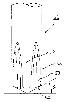
3, reference numeral 50 designates a driver bit according to
the present invention. The distal end of blade portions of the
dri ve:= bit 50 is adapted to fit bit mate flutes 32, formed as
cross flutes, at the central portion of the screw head portion
30a of a conventionally suggested screw 30 shown in Figs.6 and
7.
Accordingly, the driver bit 50 of this embodiment
comprises flat blade portions 52 for mating with the
aforementioned bit mate flutes 32 of the aforementioned screw
30 and for engaging vertical end wall portions 32a and planar
bottom portions 32b, formed at the end portions of the bit mate
flutes 32. The driver bit 50 also comprises a distal end face
of the aforementioned flat blade portions 52 or a conical
projecting portion 54 inclining at an angle 6 of from 10 to 45 ,
oreferably at an angle 0 of from 25 to 35 , relative to the
horizontal, corresponding to inclined flute portions 32c
22
CA 02321711 2007-04-05
29443-G
inclining towards the central portion of a screw neck portion
30b from the planar bottom portions 32b of the aforementioned
bit mate flutes 32.
Incidentally, reference numeral 53 designates sidewall
portions formed on the both side faces of the aforementioned
flat blade portion 52 substantially vertically and permitted
to be slightly tapered. Accordingly, the sidewall portions 53
are engageably brought into contact with sidewall portions 33
formed in the bit mate flutes 32 of the aforementioned screw
30. Accordingly, these driving faces will be provided with a
sufficiently wide engagement area, thus preventing effectively
the come-out phenomenon caused by the combination of a
conventional screw and driver bit.
Figs.4 (a) - (d) show modifications of the conical
project:ing portion 54 formed on the distal end face of the flat
blade portions 52 of the driver bit 50 according to the present
~_nvent:ion, respectively. That is, Fig.4 (a) illustrates the
conical surface of the aforementioned projecting portion 54
formed as a single tapered surface 54a. In addition, F'i.g.4 (b)
illustrates the conical surface of the aforementioned projecting
portion 54 formed as multi-stepped (two-step) tapered surfaces
54b each inclined at a different angle. Moreover, Fig.4 (c)
illus---rates the conical surface of the aforementioned projecting
portion 54 formed in cross section into the shape of a convex
sur-fface 54c. Finally, Fig.4 (d) illustrates the conical
23
CA 02321711 2007-04-05
29443--6
surface of the aforementioned projecting portion r34 formed in
cross section into the shape of a concave surface 54d.
Emboc~iment 2 (Structural example 2 of driver bit)
Fig.5 (a) and (b) illustrate another embodiment of the
flat blade portions 52 of the driver bit 50 according to the
preserit invention. That is, in this embodiment, as shown in
rig.5 (a) and (b), at least one of the flat blade portions 52
is adapted to have a notch 55, with a predetermined length and
extending from the distal end face thereof in the direction of
the bit axis.
Providing the notch 55 for the flat blade portion 52 as
such leads to a blade section 52a that will be elastically and
radially displaced from the axis center portion of the driver
bit 50. The action of the blade section 52a facilitates
retaining of the engagement of the driver bit with the bit mate
flutes 32 of the screw 30, as described later.
Embodiment 3(Structural example 1 of a screw)
Figs.6 (a) and (b) shows one structural example of the
sc-rew 30 applicable for use of the driver bit 50 according to
the present invention. That is, in Figs. 6 (a) and (b) , the screw
i.s provided with the bit mate flutes 32 on the head portion
30a. Incidentally, the bit mate flutes 32 are adapted to cross
25 with each other at right angle in the shape of a plus (+) at
24
CA 02321711 2007-04-05
29443--6
the ce:ztral portion of the screw head portion 30a. On the other
hand, the bit mate flutes 32 are adapted to form the vertical
end wall portions 32a with a predetermined depth at the end
portions thereof. In addition, the planar bottom portions 32b
are formed to orient from the lower rim portion 32a' of the end
wall portion 32a towards the central portion of the screw neck
portion 30b. Furthermore, the inclined flute portions 32c are
rormed to orient from the planar bottom portion 32b towards the
central portion of the screw neck portion 30b. Finally, a
substantially conical bottom surface 34 slightiy inclined is
Lormed at the central portion.
Incidentally, reference numeral 33 designates
substantially vertical sidewall portions formed in between the
adjacent bit mate flutes 32 as a draft taper inclined at an angle
of about from 1.5 to 2 (an angle for a header punch to be
withdrawn therefrom). Accordingly, the sidewall portions 33
are engageably brought into contact with the sidewall portions
53 of the flat blade portions 52 of the aforementioned driver
bit 50 according to the present invention.
Furthermore, like the prior-art screw with crossed flutes
shown in Fig.14, at the corners adjoining the aforementioned
bit mate flutes 32, tapered coupling surfaces 37a, 37b are
formed which extend from the position of the conical bottom
surface 34 to the opening rim portions of the bit mate flutes
32 in the screw head portion 30a.
CA 02321711 2007-04-05
29443-6
. ti
The screw 30 formed as such is provided, at the end
portions of the bit mate flutes 32 of the screw head portion
30a, with the planar bottom portions 32b, and the inclined flute
portions 32c are extendedly formed to orient from the planar
bottom portions 32b towards the central portion of the screw
neck portion 30b. The whole area of tapered contact portions
of the bit mate flutes 32 is thereby reduced to be in partial
contact with the driver bit. Moreover, this serves to make
largei: the area of the sidewall portions 33 (the area of the
surface of the screw to which the driver bit exerts torque, that
is, the area of driven surfaces) with which the distal end of
the driver bit is in contact at the boundary portions between
the adjacent bit mate flutes 32, 32.
Fig.7 illustrates the driver bit 50 according to the
cresent invention and the screw 30 shown in Figs. 6 (a) and (b) ,
mated with each other. That is, in this embodiment, as shown
in Fig.7, suppose the case where the flat blade portions 52
formed at the distal end of the driver bit 50 are brought in
contact with the bit mate flutes 32 formed in tne screw head
cortion 30a of the screw 30. Since the distal end face of the
flat blade portions 52 is formed in the shape of a conical
projecting portion 54, the flat blade portions 52 contact with
the opening rim portions of the aforementioned bit mate flutes
32 on a very small area consisting of points or lines and thus
the central portions of the both can be aligned quickly and
26
CA 02321711 2000-08-23
readily with each other. This makes it possible to less wear
and damage the screw head portion, allowing immediate and
precise mating between the driver bit 50 and the screw 30.
Embodiment 4 (Structural example 2 of screw)
Figs.8 (a) and (b) illustrate another structural example
of the screw 30 which can fit preferably the driver bit 50
according to the present invention, mated with each other. That
is, in this embodiment, as shown in Figs.8 (a) and (b), flutes
33a, 33b are formed so that the flute becomes wider radially
outwardly from the central portion of the screw head portion
30a at the sidewall portions 33, opposite to each other, of the
bit mate flute 32 of the screw 30. On the other hand, the
sidewall portions 53 at the distal end of the flat blade portions
52 of the driver bit 50 are adapted to fit the flutes 33a, 33b
that become wider outwardly, corresponding to the screw 30
formed as such. That is, the sidewall portions 53 are formed
as sidewall portions 53a, 53b that become wider outwardly.
Suppose a case where the flat blade portions 52 of the
driver bit 50 are brought into contact with the respective
sidewall portions (T1, T2, T3, and T4) of the bit mate flutes
32 of the screw 30 where the flutes 33a, 33b are formed to become
wider outwardly. In this case, forming the sidewall portions
53a, 53b to become wider outwardly at the distal end of the flat
blade portions 52 of the driver bit 50 makes as small as possible
the clearance between the aforementioned flutes 33a, 33b and
27
CA 02321711 2007-04-05
29443-6
the aforementioned sidewall portions 53a, 53b to allow
appropriate mating between the screw and the driver bit.
Moreover, the opening angle 9 of the adjacent sidewall portions
of respective flutes 33a, 33b, facing to each other, may be set
to make an acute angle slightly smaller than a right angle,
thereby ensuring the prevention of the come-out phenomenon of
the driver bit 50 in fastening screws and thus effecting
balanced torque transmission to the screw 30.
Embodinlent 5 (Structural example 3 of screw)
Figs. 9(a), (b), and (c) illustrate still another
structural example of the screw 30 which can fit preferably the
driver bit 50 according to the present invention, mated with
each other. That is, in this embodiment, as shown in
Figs. 9(a) and (b), wall portions 32aa are formed substantially
in the shape of "<" in cross section at the end portions of the
bit mate flutes 32 of the screw 30, the wall portions 32aa
being recessed inwardly (i.e., radially outwardly) a
predetermined depth from the vertical end surface. Then,
stepped bottom portions 32b' are provided to extend inwardly
and substantially in the horizontal direction from the lower
rim portions 32a' of the recessed wall portions 32aa. Moreover,
the respective inclined flute bottom portions 32c are formed to
orient from the stepped portions 32b' towards the central
portion of the screw neck portion 30b. Further, a
substantially conical bottom surface 34 slightly inclined at
the central bottom portion is formed. Other configuration is
the same as that of the screw
28
CA 02321711 2000-08-23
30 of the aforementioned embodiment 3 shown in Figs.6 (a) and
(b).
According to the screw 30 of this embodiment, the recessed
wall portions 32aa and the stepped portions 32b' are provided
at the end portions of the bit mate flutes 32 of the screw head
portion 30a, respectively. Furthermore, the respective
inclined flute portions 32c are extendedly formed to orient from
the end portions of the aforementioned stepped portions 32b'
towards the central portion of the screw neck portion 30b. The
whole area of tapered contact portions of the bit mate flutes
32 is thereby reduced to be in partial contact with the driver
bit. Moreover, this serves to make larger the area of the
sidewall portions 33 with which the distal end of the driver
bit is in contact at the boundary portions between the adjacent
bit mate flutes 32, 32.
That is, according to this embodiment, as shown in Fig.9
(c) , the distal end of the flat blade portions 52 of the driver
bit 50 fits into the respective stepped portions 32b'of the bit
mate flutes 32 of the screw 30, then the sidewall portions 53
of the aforementioned distal end of the blade portion are
brought into contact with the sidewall portions 33 of the bit
mate flutes 32 of the screw 30, and then the driver bit 50 is
rotated, thereby effecting the transmission of predetermined
torque to the screw 30. In particular, according to the
combination of the screw 30 and the driver bit 50 of this
29
CA 02321711 2000-08-23
embodiment, the portion recessed from the vertical surface
always serves as a gap portion G when the recessed wall portions
32aa formed on the end portions of the bit mate flutes 32 of
the screw 30 mate with the driver bit 50. Accordingly, forceful
fitting of the driver bit 50 therein can remove dust particles
or foreign objects in the bit mate flutes 32 by pushing them
into the aforementioned gap portion G. This will make it
possible to facilitate positive mating between the distal end
of the blade portion of the driver bit 50 and the bit mate flutes
32 of the screw 30.
In addition, according to the combination of the screw
30 and the driver bit 50 of this embodiment, when a typical plus
driver bit is used to damage the opening portion side of the
bit mate flutes 32 in screwing or unscrewing, the aforementioned
driver bit 50 can be used to remove the cut particles stacked
in the bit mate flutes 32 by pushing them into the gap portion
G. At the same time, the aforementioned driver bit 50 achieves
appropriate mating between the bottom portion side of the bit
mate flutes 32 and the distal end of the blade portion of the
driver bit 50, thus allowing screwing or unscrewing to be
completed.
Furthermore, according to the combination of the screw
and the driver bit 50 of the present invention, the driver
bit 50 can fit into the bit mate flutes 32 readily and positively
25 even when the driver bit 50 is attempted to fit into the bit
CA 02321711 2007-04-05
29443-6
mate flutes 32 while the driver bit 50 is slightly inclined
relative to the axial direction of the screw 30. This is because
the presence of the aforementioned recessed wall portions 32aa
provic.es extended degrees of freedom to the distal end of the
driver bit 50.
Embodiment 6 (Structural example 4 of screw)
Figs.10 (a) and (b) illustrate still other structural
examples of the screw 30 which can fit the driver bit 50 according
to thE: present invention, respectively.
That is, Fig.10 (a) shows a plus/minus screw 30A with a
pair of straight flutes 31a, 31b crossing with each other in
the central portion of the screw head portion 30a. According
to the plus/minus screw 30A of this embodiment, one of the
aforernentioned straight flutes 31a is adapted to form vertical
end wall portions 35a having a predetermined depth at the end
oor-_ions. In addition, the stepped portions 32b' are formed
so as to extend from the lower rim portions of the vertical end
wall portions 35a substantially in the horizontal direction.
Then, the respective inclined flute portions 32c are formed to
orient from the stepped portions 32b' towards the central
portion of the screw neck portion. Further, a substantially
conical bottom surface 34 slightly inclined at the bottom
portion is formed. In addition, the aforementioned other
straight flute 31b is formed so as to extend horizontally,
provided with a width and a depth enough to engageably contact
31
CA 02321711 2000-08-23
with the blade portion of a minus driver bit. Thus, the driver
bit 50 according to the present invention can also be used for
the plus/minus screw 30A formed as such.
Fig.10 (b) illustrates a modification of the
aforementioned plus/minus screw 30A. That is, in this case,
flutes 33a', 33b' are so formed as to become wider outwardly
in one straight flute 31a and the other straight flute 31b of
the plus/minus screw 30A, based on their correspondence with
the blade portions 52 of the aforementioned driver bit 50.
Being configured as such, the plus/minus screw 30A can provide
the same action and effect as those provided by the screw 30
of the aforementioned embodiment 4 shown in Figs.8 (a) and (b)
when the blade portions 52 of the driver bit 50 are mated with
the bit mate flutes of the plus/minus screw 30A.
Embodiment 7 (Structural example 5 of screw)
Figs.11 (a) and (b) illustrate another modification of
the plus/minus screw 30A of the aforementioned embodiment 6
shown in Figs.10 (a) and (b) That is, in this embodiment, as
shown in Figs. 11 (a) and (b) , the wall portions 32aa are formed
substantially in the shape of "<" in cross section at the end
portions of the bit mate flutes 32 with respect to one of straight
flutes 31a of the plus/minus screw 30A. Here, the wall portions
32aa are recessed inwardly a predetermined depth from the
vertical surface. Thus, the same bit mate flutes 32 as those
of the screw 30 of the aforementioned embodiment 5 shown in Fig. 9
32
CA 02321711 2000-08-23
(a) are formed.
Therefore, forming the plus/minus screw 30A as such can
provide the same action and effect as those of the screw 30
according to the aforementioned embodiment 5.
The preferred embodiments of the present invention have
been described in the foregoing. However, the present
invention is not limited to the aforementioned embodiments.
For example, in the aforementioned respective structural
examples of the screws, the present invention is also applicable
even to pan-headed or flat-headed screws. Moreover, the
respective structural examples can be effectively combined for
use. Thus, it is believed obvious that various modifications
can be made in the invention without departing from the spirit
and scope of the present invention.
As is obvious from the aforementioned embodiments, the
driver bit according to the present invention fits a screw with
substantially vertical end wall portions of a predetermined
depth, the wall portions being formed at end portions of bit
mate flutes of a screw head portion, with substantially planar
bottom portions formed to orient towards a central portion of
a screw neck portion from lower rim portions of the vertical
end wall portions, and with a conical bottom surface formed at
the central portion. The driver bit comprises flat blade
portions having substantially vertical end portions for fitting
a distal end portion thereof into the bit mate flutes of the
33
CA 02321711 2007-04-05
29443-6
screw head portionalong the verticalend wallportions, wherein
a distal end face of the flat blade portions is formed as a
conical projecting portion inclined at an angle of from 1 to
45 relative to the horizontal. When the distal end of the
aforementionedflatbladeportionsslidingly chafes against the
surfac:e of the screw head portion at the time of mating the distal
end of the driver bit with the bit mate flutes, the surface would
not be damaged at all. In addition, the distal end of the flat
blade portions fits into the screw, thereby preventing
posit-wvely the come-out phenomenon even while the driver bit
is be:ing rotated.
Furthermore, according to a combination of a driver bit
and a screw of the present invention, the flat blade portions
formed at the distal end of the driver bit is brought in contact
with the bit mate flutes formed on the screw head portion of
the screw. Since the distal end face of the flat blade portions
i s fo::med in the shape of a conical proj ected portion, the flat
blade portions contact with the opening rim portions of the
aforementioned bit mate flutes on a very small area consisting
of points or lines and thus the central portions of the both
can be aligned quickly and readily with each other. This will
make it possible to less wear and damage the screw head portion,
allowing immediate and precise mating between the driver bit
and the screw.
Furthermore, the sidewall portions are formed to become
34
CA 02321711 2000-08-23
wider outwardly at the distal end of the flat blade portions
of the driver bit and the respective sidewall portions at the
bit mate flutes of the screw are formed to become wider outwardly.
This will make as small as possible the clearance between the
driver bit and the screw. Moreover, the opening angle (3 of the
adjacent sidewall portions of respective flutes, facing to each
other, may be set to make an acute angle slightly smaller than
a right angle. The come-out phenomenon of the driver bit in
fastening screws can be thereby positively prevented and thus
balanced torque transmission to the screw can be achieved.