Language selection

Search

Patent 2321723 Summary

Third-party information liability

Some of the information on this Web page has been provided by external sources. The Government of Canada is not responsible for the accuracy, reliability or currency of the information supplied by external sources. Users wishing to rely upon this information should consult directly with the source of the information. Content provided by external sources is not subject to official languages, privacy and accessibility requirements.

Claims and Abstract availability

Any discrepancies in the text and image of the Claims and Abstract are due to differing posting times. Text of the Claims and Abstract are posted:

  • At the time the application is open to public inspection;
  • At the time of issue of the patent (grant).
(12) Patent Application: (11) CA 2321723
(54) English Title: DEVICE FOR CASTING OF METAL
(54) French Title: DISPOSITIF DE COULEE DE METAUX
Status: Deemed Abandoned and Beyond the Period of Reinstatement - Pending Response to Notice of Disregarded Communication
Bibliographic Data
(51) International Patent Classification (IPC):
  • B22D 11/01 (2006.01)
  • B22D 11/04 (2006.01)
  • B22D 11/041 (2006.01)
  • B22D 11/10 (2006.01)
  • B22D 11/115 (2006.01)
(72) Inventors :
  • LEHMAN, ANDERS (Sweden)
  • SVENSSON, ERIK (Sweden)
  • KROON, TORD (Sweden)
  • ERIKSSON, JAN-ERIK (Sweden)
(73) Owners :
  • ABB AB
(71) Applicants :
  • ABB AB (Sweden)
(74) Agent: ROBIC AGENCE PI S.E.C./ROBIC IP AGENCY LP
(74) Associate agent:
(45) Issued:
(86) PCT Filing Date: 1999-03-03
(87) Open to Public Inspection: 1999-09-10
Availability of licence: N/A
Dedicated to the Public: N/A
(25) Language of filing: English

Patent Cooperation Treaty (PCT): Yes
(86) PCT Filing Number: PCT/SE1999/000313
(87) International Publication Number: WO 1999044769
(85) National Entry: 2000-08-22

(30) Application Priority Data:
Application No. Country/Territory Date
9800736-2 (Sweden) 1998-03-06

Abstracts

English Abstract


A device for continuous or semi-continuous casting of metal comprising a
cooled mold (22) and an induction coil (10) arranged at the top end of the
mold. The mold comprises in its top end a plurality of hollow, old segments
(22a, 22b, 22c, 22d, 22e, 22f, 22'b, 22'c, 22'd) separated from each other by
partitions (26a, 26b, 26c, 26d, 26e), which all comprise an electrically
insulating barrier. Both the mold segments and the partitions are oriented
essentially in the casting direction. Each hollow top end mold segment
comprises a core of a mechanically supporting bar or beam (25a, 25b, 25c, 25d,
25e, 25f, 25'a, 25'b, 25'c, 25'd, 25'e, 25'f) arranged within the hollow mold
segment such that it is surrounded by the hollow mold segment. The core
exhibits superior mechanical properties in relation to the mold.


French Abstract

On décrit un dispositif de coulée continue ou semi-continue de métaux, qui comprend un moule refroidi (22) et une bobine d'induction (10) disposée au sommet du moule. Le moule comprend, à son extrémité supérieure, une pluralité de segments du moule (22a, 22b, 22c, 22d, 22e, 22f, 22'b, 22'c, 22'd) séparés les uns des autres par des cloisons (26a, 26b, 26c, 26d, 26e) toutes munies d'une barrière isolante. Tant les segments du moule que les cloisons sont essentiellement orientés dans le sens de la coulée. Chaque segment du moule creux de l'extrémité supérieure comprend un coeur de barre ou de poutre de soutien mécanique (25a, 25b, 25c, 25d, 25e, 25f, 25'a, 25'b, 25'c, 25'd, 25'e, 25'f) disposé à l'intérieur du segment du moule creux et encadré par ce dernier. Le coeur présente des propriétés mécaniques supérieures en relation avec le moule.

Claims

Note: Claims are shown in the official language in which they were submitted.

12
CLAIMS
1. A device for continuous or semi-continuous casting of metal comprising,
- a cooled mold (22) and an induction coil (10) arranged at the top end of the
mold,
- wherein the mold in its top end comprises a plurality of mold segments and a
plurality of
partitions (26a, 26b, 26c, 26d, 26e) oriented essentially in the casting
direction and arranged
to divide the mold into segments which also are oriented essentially in the
casting direction
and that each partition comprises an electrically insulating barrier,
characterized in that
- the top end mold segments (22a, 22b, 22c, 22d, 22e, 22f, 22'b, 22'c, 22'd)
are hollow and
comprise a core (25a, 25b, 25c, 25d, 25e, 25f, 25'a, 25'b, 25'c, 25'd, 25'e,
25'f)of a mechanically
supporting bar or beam surrounded by the hollow mold segment shell, wherein
the core
exhibits superior mechanical properties in relation to the mold.
2. A device according to claim 1, characterized in that the mold (22) in its
lower parts,
downstream of the coil (10), is associated with a mold back-up structure of
beams or plates
arranged outside the mold.
3. A device according to claim 1 or 2, characterized by one integral mold,
that the
mold (22)in the top end is divided into a plurality of hollow mold segments
(22a, 22b, 22c,
22d, 22e, 22f, 22'b, 22'c, 22'd) separated from each other by partitions (26a,
26b, 26c, 26d,
26e) and that a mechanically supporting bar or beam (25a, 25b, 25c, 25d, 25e,
25f, 25'a, 25'b,
25'c, 25'd, 25'e, 25'f) is arranged within each hollow mold segment.
4. A device according to claim 1 or 2, characterized in that the mold (22)
exhibits an
essentially square or rectangular cross section and comprises four mold
plates, that each of
the mold plates in the top end is divided into a plurality of hollow mold
segments (22a, 22b,
22c, 22d, 22e, 22f, 22'b, 22'c, 22'd) by partitions (26a, 26b, 26c, 26d, 26e)
and that a
mechanically supporting bar or beam (25a, 25b, 25c, 25d, 25e, 25f, 25'a, 25'b,
25'c, 25'd, 25'e,
25'f) is arranged within each hollow mold segment.

13
5. A device according to claim 3 or 4, characterized in that the mold (22)
comprises a
plurality of elongated hollow mold segments (22a, 22b, 22c, 22d, 22e, 22f,
22'b, 22'c, 22'd)
separated from each other by partitions (26a, 26b, 26c, 26d, 26e) that a
mechanically supporting
bar or beam (25a, 25b, 25c, 25d, 25e, 25f, 25'a, 25'b, 25'c, 25'd, 25'e, 25'f)
is arranged
in each hollow mold segment, that the elongated hollow mold segments extend
over the full
height of the mold and that the assembly of elongated hollow segments are held
together and
mechanically supported by the mold back-up structure.
6. A device according to any of the preceding claims, characterized in that
any bar or
beam (25a, 25b, 25c, 25d, 25e, 25f, 25'a, 25'b, 25'c, 25'd, 25'e, 25'f)
comprised as a core in
the hollow mold segments (22a, 22b, 22c, 22d, 22e, 22f, 22'b, 22'c, 22'd) at
the top end of the
mold (22) is mechanically associated with this mold back-up structure.
7. A device according to any of claims 1 to 5, characterized in that the bars
or beams
comprised as cores (25'a, 25'b, 25'c, 25'd, 25'e, 25'f) in the hollow mold
segments (22a, 22b,
22c, 22d, 22e, 22f, 22'b, 22'c, 22'd) at the top end of the mold (22) are
joined, downstream the
partitions (26a, 26b, 26c, 26d, 26e), to form an integral mold back-up
structure (25")or plate.
8. A device according to any of the preceding claims, characterized in that
the hollow
mold segments (22a, 22b, 22c, 22d, 22e, 22f, 22'b, 22'c, 22'd) have an
essentially square or
rectangular cross-section and are arranged around the cores (25a, 25b, 25c,
25d, 25e, 25f,
25'a, 25'b, 25'c, 25'd, 25'e, 25'f).
9. A device according to any of the preceding claims, characterized in that
the hollow
mold segments (22a, 22b, 22c, 22d, 22e, 22f, 22'b, 22'c, 22'd) have a minimum
wall
thickness corresponding to one penetration depth for the magnetic field
generated by the coil or
more.
10. A device according to any of the preceding claims, characterized in that
the hollow
mold segments (22'b, 22'c, 22'd) have an increased wall thickness on the side
facing the melt.

14
11. A device according to any of the preceding claims, characterized in that
the hollow
mold segments (22a, 22b, 22c, 22d, 22e, 22f, 22'b, 22'c, 22'd) on the outside
faces of the
mold extend from the top end of the mold to a level approximately at a level
corresponding to
the depth of the partitions.
12. A device according to any of the preceding claims, characterized in that
the cores
(25a, 25b, 25c, 25d, 25e, 25f) extend essentially from the top end of the mold
to a level below
the lower end of the partitions (26a, 26b, 26c, 26d, 26e).
13. A device according to claim 12, characterized in that the cores (25a, 25b,
25c, 25d,
25e, 25f) extend over essentially the full length of the mold (22).
14. A device according to any of the preceding claims, characterized in that
the cores
(25a, 25b, 25c, 25d, 25e, 25f, 25'a, 25'b, 25'c, 25'd, 25'e, 25'f) are
inserted into cavities (24)
which are closed at the top end of the mold.
15. A device according to any of the claims 1 to 13, characterized in that the
cores (25a,
25b, 25c, 25d, 25e, 25f, 25'a, 25'b, 25'c, 25'd, 25'e, 25'f) are inserted into
cavities (24) which
are open at the top end of the mold, such that the cores face the top end
surface of the mold.
16. A device according to any of the preceding claims, characterized in that
the mold
(22) comprises copper or a copper alloy and that the mechanically supporting
bars or beams
(25a, 25b, 25c, 25d, 25e, 25f, 25'a, 25'b, 25'c, 25'd, 25'e, 25'f) comprise
steel.
17. A device according to any of the preceding claims, characterized in that
the mechanically
supporting bars or beams (25a, 25b, 25c, 25d, 25e, 25f, 25'a, 25'b, 25'c,
25'd, 25'e,
25'f) comprise internal channels or cavities for flowing coolant.
18. A device according to any of the preceding claims, characterized in that
channels
for a flowing coolant are arranged within the hollow mold segments (22a, 22b,
22c, 22d, 22e,
22f, 22'b, 22'c, 22'd).

15
19 A device according to any of the preceding claims, characterized in that
channels
for a flowing coolant are arranged in the interface between the hollow mold
segment (22a,
22b, 22c, 22d, 22e, 22f, 22'b, 22'c, 22'd)and the supporting bar or beam (25a,
25b, 25c, 25d,
25e, 25f, 25'a, 25'b, 25'c, 25'd, 25'e, 25'f).
20. A device according to any of the preceding claims, characterized in that
the induction
coil (10) is supplied with an alternating current having a base frequency of
50 Hz or
more.
21. A device according to claim 20, characterized in that the induction coil
(10) is
supplied with an alternating current having a base frequency of 1-200 kHz.
22. Use of a device, according to any of the preceding claims for continuous
or
semi-continuous casting of metals, comprising a cooled mold (22) and an
induction coil (10)
arranged at the top end of the mold, wherein the mold comprises in its top end
a plurality of
hollow mold segments (22a, 22b, 22c, 22d, 22e, 22f, 22'b, 22'c, 22'd)
separated from each
other by electrically insulating partitions (26a, 26b, 26c, 26d, 26e).

Description

Note: Descriptions are shown in the official language in which they were submitted.


CA 02321723 2000-08-22
WO 99/44769 PCT/SE99/00313
DEVICE FOR CASTING OF METAL
TECHNICAL FIELD
The present invention relates to a device for continuous or semi-continuous
casting of metal or
metal alloys into an elongated strand. where the strand is cast using a device
comprising a
cooled continuous casting mold and an induction coil arranged at the top end
of the mold. The
coil is supplied with a high frequency alternating current from a power
supply. The invented
device exhibits improved mechanical strength.
BACKGROUND ART
During continuous or semi-continuous casting of metals and metal alloys, a hot
metal melt is
supplied to a cooled continuous casting mold, i.e. a mold which is open in
both ends in the
casting direction. The mold is typically water-cooled and surrounded and
supported by a struc-
ture of support beams. Melt is supplied to the mold where the metal is
solidified and a cast
strand is formed as it is passed through the mold. A cast strand leaving the
mold, comprises a
solidified, self supporting surface layer or shell around a residual melt.
Generally it can be said
that conditions of initial solidification is critical for both quality and
productivity. A lubricant is
typically supplied to the upper surface of the melt in the mold. The lubricant
serves many
purposes, amongst others it will prevent the skin of the cast strand first
developed from sticking
to the mold wall. Normal adherence between oscillation show as so called
oscillation marks.
Should the solidified skin stick or adhere more severely to the mold it will
show as severe
surface defects and in some cases as ripping of the first solidified skin. For
large dimension
strands of steel the lubricant is predominantly a so-called mold powder
comprising glass or
glass forming compounds that is melted by the heat at the meniscus. The mold
powder is often
continuously added to the upper surface of the melt in the mold during
casting, as an essentially
solid, free flowing particulate powder. The composition of a mold powder is
customized.
Thereby the powder will melt at a desired rate and lubrication will be
provided at the desired
rate to ensure lubrication. A too thick layer of lubricant between mold and
cast strand will also
affect the solidification conditions and surface quality in an undesired way,
thus the thermal
conditions at the meniscus need to be controlled. For smaller strands and for
non-ferrous metals

CA 02321723 2000-08-22
WO 99/44769 PCT/SE99/00313
2
oil, typically vegetable oil, or grease is used as lubricant. Irrespective of
what type of mold
lubricant is used it should preferably be fed into the interface cast
strand/mold at an even rate
sufficient to form a thin uniform film in the interface to avoid surface
defects originating from
adherence between mold and strand. A too thick film might cause uneven surface
and disturbs
the thermal situation.
Heat losses and overall thermal conditions at the meniscus are predominantly
controlled by the
secondary flow that is developed in the mold. The use of an inductive HF
heater or another HF-
device used for electromagnetic casting, an EMC-device, for influencing the
thermal situation at
the top end is discussed in e.g. US-A-5 375 648 and in earlier not yet
published Swedish Patent
Application No. SE9703892-1. High thermal losses are compen$ated by a supply
of heat to the
upper surface, either by a controlled upward flow of hot melt or by a heater,
othenvise the
meniscus can start to solidify. Such a solidification will severely disturb
the casting process and
destroy the quality of the cast product in most aspects.
A high frequency inductive heater arranged at the top end of a continuous
casting mold will
provide means to improve the capability to control the temperature of the
metal at the upper
surface of the melt, the meniscus, and at the same time generate compressive
forces acting to
separate the melt and the mold, thereby reducing the risk for sticking,
reducing oscillation mark
and in general provide improved conditions for mold lubrication. This
technique, which today is
referred to as electromagnetic casting, EMC, for an improved lubrication and
thus improved
surfaces is primarily attributed to the compressive forces acting to separate
the melt from the
mold. The inductive heater or coil may be of single-phase or poly-phase
design. Preferably a
high-frequency magnetic alternating field is applied. The compressive forces,
generated by the
high frequency magnetic field, reduce the pressure between the mold wall and
the melt,
whereby the conditions for lubrication are significantly improved. Surface
quality of the cast
strand is improved and the casting speed can be increased without risking the
surface quality.
Oscillation is primarily applied to ensure that the cast strand leaves the
mold. As the compres-
sive forces act to separate the melt from the mold they will minimize any
contact between the
melt and mold during initial solidification of the skin and improve the feed
of lubricant hereby
further improving the surface quality of the cast strand. The use of an
induction coil supplied

CA 02321723 2000-08-22
WO 99/44769 PCT/SE99/00313
3
with a high frequency alternating current and arranged at the meniscus is
believed to provide a
means to substantially improve surface quality, internal structure,
cleanliness and also produc-
tivity. To increase the penetration of a high frequency magnetic field through
a mold and into
the melt it is known to use a Cu- mold which at the top end of the mold, i.e.
at level with the
high frequency induction heater is slitted in the casting direction. The
slitted mold will reduce
the eddy-current losses and increase the heat efficiency as the current paths
for the electrical
currents induced in the mold by the applied magnetic field is cut. Such molds,
known as cold
crucible molds, are used for other purposes and are typically used as billet
molds and the like,
i.e. molds for small sized strands typically with an essentially square cross-
section of 200x200
mm or less. The Cu-mold is favorable due to its high heat conductivity and
high electrical
conductivity but has a short coming in its mechanical strength.
SUMMARY OF THE INVENTION
It is an object of the invention to provide a device for continuous casting of
metal strand,
wherein the conditions for the initial solidification of the cast metal in the
mold are improved
and in particular the conditions for mold lubrication are improved by the use
of an EMC that
exhibits low electromagnetic losses. In particular it is an object of the
present invention to
provide a device comprising a so called cold crucible mold, i.e. a mold that
in its top end is
slitted and thereby divided into segments which exhibit an improved mechanical
integrity
without any increase in the induced power losses.
A continuous casting device according to the present invention shall ensure
good conditions
for initial solidification within a mechanically stable mold for use together
with EMC,
wherein a good and controlled thermal flow, lubrication and overall conditions
at the top end
of the mold is provided, thus attaining considerable improvements with respect
to quality and
productivity. This is accomplished by the present invention, which according
to one aspect
provides a method for continuous or semi-continuous casting of metal according
to the pre-
amble of claim 1, which is characterized by the features of the characterizing
part of claim.
Further developments of the device are characterized by the features of
additional claims 2 to

CA 02321723 2000-08-22
WO 99/44769 PCTfSE99/00313
21. It is also an object of the present invention to provide a use of such
continuous casting
device, which is defined in claim 22.
DESCRIPTION OF THE INVENTION
A device for continuous or semi-continuous casting of metal where hot melt is
supplied to a
cooled continuous casting mold, the melt is cooled and at least partly
solidified to a strand
which is extracted from the mold and further cooled and solidified downstream
of the mold
and which comprises an induction coil arranged at the top end of the mold is
to reduce the
induced power losses typically arranged with the top end of the mold slitted
into a plurality of
mold segments where each slot between two mold segments is filled with a
partition com-
prising an electrically insulating barner, The partitions and the mold
segments are oriented
essentially in the casting direction. To meet the objectives mentioned in the
foregoing to im-
prove the mechanical properties of such a device for continuous or semi-
continuous casting of
metal comprising a cooled mold and an induction coil arranged at the top end
of the mold,
where the mold in its top end comprises a plurality of mold segments and a
plurality of parti-
tions oriented essentially in the casting direction and arranged to divide the
mold into seg-
ments which also are oriented essentially in the casting direction and that
each partition com-
prises an electrically insulating barrier the present invention provides a
mold with top end
mold segments that are hollow and comprises a core of a mechanically
supporting bar or
beam, such that the mechanically supporting core is surrounded by the hollow
mold segment
shell, wherein the supporting core exhibits superior mechanical properties in
relation to the
mold. In particular the stiffness and strength, tensile and bending strength,
is higher for the
core than for the mold. It is also favorable with a core exhibiting a high
fatigue strength and a
high toughness. Typically the mold exhibits an electrical conductivity higher
than the electri-
cal conductivity of the core, but this is no requirement as the low
penetration depth of the HF-
magnetic field limits the penetration and induction of currents to the shell
and essentially no
currents are induced in the reinforcing or supporting core. These mechanically
reinforced
mold segments according to the present invention are as known from prior art
separated from
each other by electrically insulating partitions Thus a device according to
the present inven-
tion provides a mechanically stable mold without an increase in the induced
power losses.

CA 02321723 2000-08-22
WO 99/44769 PCT/SE99/00313
When the coil is supplied with an alternating electric high frequency current
and a high fre-
quency magnetic field is generated to act upon the melt in the top end of the
mold the hollow
mold segment, which is arranged as a shell or shield around the supporting
core, provides a
favorable circuit for any electrical currents induced in the mold. These
currents are by the
partitions restricted to one segment and the induced power losses are limited
by the electrical
properties of the mold, which typically comprises copper, a copper alloy or
other metal with a
high thermal and electrical conductivity. Thereby is the risk for high induced
power losses in
the supporting beams or bars substantially reduced. As the induced power
losses remain low
also in the mechanically improved mold comprised in a device according to the
present in-
vention a large proportion of the applied power penetrates into the melt where
it is induced to
develop heat in and most important to generate the desired compressive forces
acting to sepa-
rate the melt from the mold wall.
Typically the mold in its lower parts downstream of the coil is associated
with a mold back-
up structure of beams or plates arranged outside the mold. This back-up
structure, which
normally is referred to as water-beams, is normally assembled from steel
beams. The steel
beams comprise internal channels for a flowing coolant such as water.
According to one embodiment suitable for casting of smaller dimensions and
especially non-
ferrous metals such as aluminum or copper the mold is made in one piece. This
one-piece
integral mold is, in the top end, divided into a plurality of segments. The
segments are sepa-
rated from each other by partitions. Each of the top end segments is hollow
and a mechani-
cally supporting bar or beam is arranged within each hollow segment.
Alternatively the mold exhibits an essentially square or rectangular cross
section for casting
of billets, slabs or blooms. Such a mold comprises four mold plates, where
each mold plate in
the top end is divided into a plurality of segments by partitions. In
accordance with the pres-
ent invention each of the top end segments is hollow and a mechanically
supporting bar or
beam is arranged within each hollow segment.

CA 02321723 2000-08-22
WO 99/44769 PCT/SE99/00313
6
According to further alternative embodiments the mold comprises a plurality of
elongated
hollow mold segment separated from each other by partitions. A mechanically
supporting bar
or beam is arranged as a core in each hollow segment. The hollow mold segments
are pref
erably made in the form of sleeves, with the top end closed, into which the
cores are inserted.
Alternatively tubes, with both ends open, are used as hollow mold segments
such that the
mold formed exhibits the cores exposed at the top end.
An assembly of hollow mold segments are held together and mechanically
supported by the
mold back-up structure. The elongated hollow mold segments and its associated
core can in
some embodiments extend over the full height of the mold but typically the
hollow mold
segments are restricted to the top end of the mold, at level with the
induction coil, while the
bottom part of the mold, downstream of the induction coil, is comprised of an
integral mold
or four plates Of course can the hollow mold segments at the top end be joined
with the bot-
tom part of the mold to form one integral mold or a mold comprising four mold
plates.
The cores in a mold according to the present invention needs to cover at least
the full length
of the hollow mold segments, i.e. the full length of the partitions, and also
to extend over part
of the bottom part. When required for mechanical reasons the cores extend over
the full
length of the mold. Any bar or beam comprised as a core in the mold segments
at the top end
of the mold is mechanically associated with this mold back-up structure. This
association can
either be direct or through the surrounding hollow mold segment. According to
one embodi-
ment of the present invention the bars or beams comprised as cores in the top
end mold seg-
ments are joined downstream of the partitions and the hollow mold segments to
form an inte-
gral plate or other form of back-up structure.
Typically the hollow mold segments have an essentially square or rectangular
cross-section
and are arranged around the core, but they can have any suitable form.
According to some
embodiments the side facing away from the mold has a rounded or pointed
surface shape to
further reduce the induced power losses, while the mold segments on the melt
side always
have a shape in conformity with the internal shape or contour of the mold. The
surfaces of the

CA 02321723 2000-08-22
WO 99/44769 PCT/SE99/00313
7
mold segments in contact with the partitions need to be sufficiently wide to
provide a suffi-
cient mold thickness to eliminate any risks for melt penetrating the mold.
According to one preferred embodiment the hollow mold segment has a minimum
wall thick-
ness corresponding to one penetration depth for the magnetic field generated
by the coil or
more to minimize the induced power losses.
To facilitate a longer working life for the mold the hollow mold segments are
according to
one embodiment provided with an increased wall thickness on the side facing
the melt.
According to one embodiment the height of the hollow mold segments differ
between the
melt side and the outside such that the hollow mold segments on the outside
faces of the mold
extend from the top end of the mold to a level approximately at a level
corresponding to the
depth of the partitions.
Typically the mold comprises a copper or a copper alloy and that the
mechanically support-
ing bars or beams inserted in the hollow mold segments comprise steel.
The mechanically supporting bars or beams inserted in the hollow mold segments
preferably
comprise internal channels or cavities for flowing coolant. Channels for a
flowing coolant are
when deemed appropriate arranged within the hollow mold segments or in the
interface be-
tween the hollow mold segment and the supporting bar or beam.
Typically the induction coil is supplied with an alternating current having a
base frequency of
50 Hz or more. Preferably the alternating current has a base frequency of 1-
200 kHz.
The device according to the present invention is suitable for continuous or
semi-continuous
casting of metals such as steel, copper, aluminum and the like.

CA 02321723 2000-08-22
WO 99/44769 PC"T/SE99/00313
8
BRIEF DESCRIPTION OF THE DRAWINGS
In the following the invention will be explained in greater detail and be
exemplified by means
of preferred embodiment with reference to the accompanying figures;
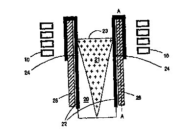
Figure 1 shows a cut along the casting direction for a device according to one
embodiment of
the present invention;
Figure 2 shows in detail a part of the mold wall cut across the casting
direction for one em-
bodiment of the present invention;
Figure 3 shows in detail a part of the mold wall cut across the casting
direction for one alterna-
tive embodiment of the present invention;
Figure 4 shows in detail a part of a mold wall along a cut A-A in the casting
direction for one
embodiment of the present invention; and
Figure 5 shows in detail a part of a mold wall along a cut A-A in the casting
direction for one
alternative embodiment of the present invention.
DESCRIPTION OF THE PREFERRED EMBODIMENTS
The device for continuous casting of metal shown in the Figure 1 comprises a
continuous
casting mold assembly comprising a mold 22 and a mold back-up structure 25
according to
the present invention. The continuous casting mold is open in both ends in the
casting direc-
tion and is arranged with cooling means, not shown. The continuous casting
machine also
includes means for supply of hot melt to the mold and means for ensuring that
the formed cast
strand continuously leaves the mold, not shown, and when appropriate means for
oscillating
the mold, not shown. The mold 22 is continuously supplied with a primary flow
of hot melt,
the hot metal 21 is cooled and a cast strand 20 is formed in the mold 22. The
mold 22 is usu-
ally a water-cooled copper mold. The mold 22 comprises at its top end a cavity
24 into which

CA 02321723 2000-08-22
WO 99/44769 PCT/SE99/00313
9
a support beam 25 is inserted as a reinforcing or supporting core. As the
metal passes through
the mold 22 it is cooled and solidified whereby a cast strand 20 is formed.
When the cast
strand 20 leaves the mold 22, it comprises a solidified, self supporting
surface shell 20 around
a remaining residual melt 21. Generally it can be said that the surface
conditions and of
course the cast structure is highly dependent on the conditions of initial
solidification. But
also metal cleanliness will depend on the conditions in the top end of the
mold, i.e. the loca-
tions at which the metal starts to solidify and the conditions at the
interface mold/strand and
at the meniscus. To control the thermal situation at the top end of the mold
22 and the lubri-
cating conditions is a device for generation of a high frequency magnetic
field e.g. an induc-
tion coil 10 arranged at this top end at level with the top surface of the
melt in the mold, the
meniscus 23. The coil 10 as shown in figure 1 is arranged outside the mold 22.
The induction
coil 10 may be a single-phase or a poly-phase heater. When the high frequency
magnetic al-
ternating field is applied to act on the melt 21, heat is developed in the
melt 21 so that the
temperature of the melt adjacent to the meniscus 23 can be controlled. At the
same time com-
pressive forces acting on the melt 21 are developed by the high frequency
alternating field.
The compressive forces reduce the pressure between the mold 22 and the melt 21
and thus
impmve the condition for lubrication significantly. Improvements obtained when
casting ac-
cording to the present invention relates to a new device for electromagnetic
casting, EMC,
with improved mechanical properties at the top end of the mold at level with
the induction
coil 10 and meniscus 23 and low induced power losses.
The device according to the present invention comprises, as shown in figure 2
to 5 in the top
end of the mold 22 a plurality of hollow mold segments 22a- f, 22'b-22'd,
separated from each
other by partitions 26a- 26e. A mechanically supporting bar or beam 25 a -25 f
is arranged
within each hollow mold segment 22a- f, 22'b-22'd. Such a bar exhibits
superior mechanical
properties in relation to the mold. In particular the stiffness, the bending
strength and the ten-
sile strength is higher for the core than for the mold. It is also favorable
with a core exhibiting
a high fatigue strength and high toughness. Any bar or beam 25a -25f comprised
as a core in a
the hollow mold segments 22a- f, 22'b-22'd at the top end of the mold is
mechanically associ-
ated with the remaining parts of the mold back-up structure 25 at the lower
end of the mold
assembly. The bars or beams 25a -25f can extend over the full length of the
mold 22 or as in

CA 02321723 2000-08-22
WO 99/44769 PCT/SE99/00313
figure 4 at least over the full length of the partitions 26a, 266,26c,26d and
26e. According to
the embodiment shown in figure 5 the bars 25'a -25'f are merged to a back-up
plate 25"
downstream of the partitions 26a, 26b,26c,26d and 26e or the coil 10. Thus the
bars or beams
comprised as cores in the hollow mold segments at the top end of the mold form
an integral
part of the mold back-up structure or the mold back-up plate arranged outside
the mold or
mold plate respectively. The cores can as indicated in figure 4 be inserted
into cavities which
are open in the top end such that they face the top surface of the mold or the
cores can as in-
dicated in figure 5 be covered in the top end by the mold, i.e. the cores are
inserted into cavi-
ties 24 which are closed in the top end.
The hollow mold segments 22a- f, 22'b-22'd shown in figures 2 and 3 have an
essentially
square or rectangular cross-section and are arranged around the essentially
square cores 25a -
25f, 25'a -25'f, but the mold segments and the cores can exhibit any cross-
sectional shape as
long as the melt side of the hollow segments are in conformity with the
internal contour or
shape of the mold. The hollow mold segments 22a- f, 22'b-22'd have a minimum
wall thick-
ness corresponding to one penetration depth for the magnetic field generated
by the coil or
more. According to the embodiment shown in figure 2 the wall thickness of the
hollow mold
segments 22b, 22c, 22d is the same for all walls, while the hollow mold
segments 22'b,22'c,
22'd according to the embodiment shown in figure 3 have an increased wall
thickness on the
side facing the melt. The cavity in the hollow mold segments 22a- f, 22'b-22'd
typically ex-
tends, as indicated in figure 1, from the top end of the mold to a level
approximately at a level
corresponding to the depth of the partitions 26a -26d, but can also extend
over the full length
of the mold if this is deemed appropriate. The mold 22 typically comprises
copper or a copper
alloy and the mechanically supporting bars or beams 25a -25f, 25'a -25'f
inserted in the hol-
low mold segments 22a- f, 22'b-22'd typically comprises steel. The
mechanically supporting
bars or beams 25a -25f, 25'a -25'f, which are inserted in the hollow mold
segments 22a- f,
22'b-22'd comprise according to the embodiments shown in figures 2 and 3
channels 27 for a
flowing coolant arranged in the interface between the hollow mold segment 22b-
d, 22'b-22'd
and the supporting bar or beam 25a -25d. Such channels can also be arranged
within the bar
or beam, 25a -25d and/or within the hollow mold segments 22b- d, 22'b-22'd.

CA 02321723 2000-08-22
WO 99/44769 PCT/SE99/00313
11
The mold typically exhibits an essentially square or rectangular cross section
and comprises
four mold plates or when suitable such as for casting of small dimensions or
non-ferrous met-
als can be made as one integral one-piece mold.
The induction coil is typically supplied with an alternating current having a
base frequency of
50 Hz or more, preferably with an alternating current having a base frequency
of 1-200 kHz.
With a device according to the present invention and the embodiments shown in
the figures
many quality and productivity aspects such as;
- Heat efficiency;
- More mechanically stable mold;
- Cleanliness;
- Surface quality;
- Controlled cast structure;
- Reduced down-time; and
- Provisions to increase casting speed and /or reduce oscillation,
can be achieved without unnecessary induced power losses or short-comings due
to unsatis-
factory mechanical properties at the top end of the mold.

Representative Drawing
A single figure which represents the drawing illustrating the invention.
Administrative Status

2024-08-01:As part of the Next Generation Patents (NGP) transition, the Canadian Patents Database (CPD) now contains a more detailed Event History, which replicates the Event Log of our new back-office solution.

Please note that "Inactive:" events refers to events no longer in use in our new back-office solution.

For a clearer understanding of the status of the application/patent presented on this page, the site Disclaimer , as well as the definitions for Patent , Event History , Maintenance Fee  and Payment History  should be consulted.

Event History

Description Date
Inactive: IPC from MCD 2006-03-12
Application Not Reinstated by Deadline 2004-03-03
Time Limit for Reversal Expired 2004-03-03
Deemed Abandoned - Failure to Respond to Maintenance Fee Notice 2003-03-03
Letter Sent 2001-03-19
Inactive: Single transfer 2001-02-21
Inactive: Cover page published 2000-11-28
Inactive: First IPC assigned 2000-11-22
Inactive: Courtesy letter - Evidence 2000-11-14
Inactive: Notice - National entry - No RFE 2000-11-08
Application Received - PCT 2000-11-03
Application Published (Open to Public Inspection) 1999-09-10

Abandonment History

Abandonment Date Reason Reinstatement Date
2003-03-03

Maintenance Fee

The last payment was received on 2001-12-21

Note : If the full payment has not been received on or before the date indicated, a further fee may be required which may be one of the following

  • the reinstatement fee;
  • the late payment fee; or
  • additional fee to reverse deemed expiry.

Please refer to the CIPO Patent Fees web page to see all current fee amounts.

Fee History

Fee Type Anniversary Year Due Date Paid Date
Basic national fee - standard 2000-08-22
MF (application, 2nd anniv.) - standard 02 2001-03-05 2000-12-19
Registration of a document 2001-02-21
MF (application, 3rd anniv.) - standard 03 2002-03-04 2001-12-21
Owners on Record

Note: Records showing the ownership history in alphabetical order.

Current Owners on Record
ABB AB
Past Owners on Record
ANDERS LEHMAN
ERIK SVENSSON
JAN-ERIK ERIKSSON
TORD KROON
Past Owners that do not appear in the "Owners on Record" listing will appear in other documentation within the application.
Documents

To view selected files, please enter reCAPTCHA code :


To view images, click a link in the Document Description column. To download the documents, select one or more checkboxes in the first column and then click the "Download Selected in PDF format (Zip Archive)" or the "Download Selected as Single PDF" button.

List of published and non-published patent-specific documents on the CPD .

If you have any difficulty accessing content, you can call the Client Service Centre at 1-866-997-1936 or send them an e-mail at CIPO Client Service Centre.


Document
Description 
Date
(yyyy-mm-dd) 
Number of pages   Size of Image (KB) 
Representative drawing 2000-11-28 1 8
Description 2000-08-22 11 599
Claims 2000-08-22 4 175
Abstract 2000-08-22 1 64
Drawings 2000-08-22 3 78
Cover Page 2000-11-28 1 52
Reminder of maintenance fee due 2000-11-06 1 112
Notice of National Entry 2000-11-08 1 195
Courtesy - Certificate of registration (related document(s)) 2001-03-19 1 113
Courtesy - Abandonment Letter (Maintenance Fee) 2003-03-31 1 178
Reminder - Request for Examination 2003-11-04 1 112
Correspondence 2000-11-08 1 14
PCT 2000-08-22 7 323