Note: Descriptions are shown in the official language in which they were submitted.
CA 02321754 2000-08-22
WO 99/42857 PCT/US99/03606
-1-
SINGLE WELL SYSTEM FOR MAPPING SOURCES OF
ACOUSTIC ENERGY
Field of the Invention
This invention relates to geophysical apparatus and methods. More
particularly, a system is provided for locating the sources of microseismic
events or
other acoustic waves around a well.
Background of the Invention
Low-energy acoustic waves are created in solids when stresses in the solid
cause sudden movement of fractures or zones of weakness. The energy release
may
be referred to as "acoustic emission" or, more commonly when the solid is a
formation in the earth, the energy release is called a "microseismic event."
Microseismic events may be caused by fluid pressure changes in the pore spaces
of
rock, which cause stress changes in the rock and movement at planes of
weakness, or
by the formation of hydraulic fractures. The seismic wave generated can be
considered to be an extremely weak earthquake. It has been known for many
years
that such microseismic events occur in hydrocarbon reservoirs in which
substantial
pressure changes occur.
Hydraulic fracturing of wells is widely practiced as a method for increasing
the production rate of the wells. In this method, fluid is injected at a high
rate and at a
20 pressure greater than the earth stress in the formation to be fractured.
Typically, a
vertical hydraulic fracture is created around a well, and the fracture may
extend
several hundred feet from the well. The fracture may also extend significant
distances
along the wellbore.
It is important to know the extent of a hydraulic fracture along a wellbore,
so
that it can be determined if the fracture has grown to intersect other
permeable zones
above or below the zone of interest. It is also desirable to know the length
of the
fracture away from the wellbore and the direction or azimuth angle of the
fracture
CA 02321754 2000-08-22
WO 99/42857 PCTNS99/03606
-2-
extending away from the well, so that the influences of the fracture on flow
of fluids
in the zone of interest can be predicted with greater accuracy.
It is also important to know whether a hydraulic fracture has penetrated an
impermeable barrier layer during injection of a fluid into a well for disposal
purposes.
5 Such fluid may be a brine, radioactive material, or a hazardous chemical
waste stream,
for example. It is desirable to have a tool which can detect possible movement
of the
fluid and any solids it may contain out of the intended injection zone.
Detection of
microseismic events originating beyond an impermeable barner which bounds the
intended injection zone can indicate such movement.
10 Not surprisingly, a large number of microseismic events are associated with
the hydraulic fracturing process. Several years ago it was found that an
indication of
hydraulic fracture direction or azimuth angle can be derived from microseismic
events
occurring soon after the hydraulic fracture is formed. Early work was reported
by
Dobecki in "Hydraulic Fracture Orientation Using Passive Borehole Seismics,"
Soc.
15 of Pet. Engrs. Paper No. 12110, 1983. Data from microseismic events were
analyzed
to determine the polarization of the compressive wave (P-wave) from each event
to
determine azimuth direction of the event, the polarization being determined
from a
"hodogram." A hodogram is a plot of the output of a geophone in one direction
versus the output of a geophone in another direction, such as the x-direction
versus the
20 y-direction. The distance from the event to the well was calculated by
measuring the
difference in arrival time of the P-wave and the shear wave (S-wave) at the
well and
multiplying this difference by a factor involving the respective P-wave and S-
wave
velocities. A histogram of the seismic events following hydraulic fracturing
was also
plotted in polar coordinates to indicate the azimuthal distribution of events
and
25 consequently, the direction of the hydraulic fracture.
Much more recently, examination of seismic events received in a well during
hydraulic fracturing, pressure fall-off after fracturing, and flow-back of
fluid was
reported in "Acoustic Emission Monitoring During Hydraulic Fracturing," PE
Formation Evaluation Journal, pp. 139-144, June 1992. It was pointed out in
this
30 paper that when detecting microseismic events with a single set of triaxial
geophones,
CA 02321754 2000-08-22
WO 99/42857 PCT/US99/03606
-3-
an ambiguity of 180° exists in the vertical or z-direction. The
polarity of the first
motion on arrival of a wave is not known because a source above or below' the
receiver may produce an identical signal.
A method of locating fractures from acoustic emissions received by single
S geophones placed in wells at a known distance from the well being fractured
was
reported in "Observations of Broad Band Microseisms During Reservoir
Stimulation,"
Society of Exploration Geophysics 63rd Conference, Washington, 1993. This
method
is relatively expensive in that multiple wellbores must be used and multiple
tools must
be run. Triangulation calculations are used to locate the source of seismic
events
using the signals received in the separate wells.
Microseismic events may be produced in the subsurface by processes other
than hydraulic fracturing of wells or pressure changes in a reservoir.
Subsidence
accompanying reservoir pressure reduction may also lead to movement of piles
or
other equipment at the surface or seabed above a reservoir, for example,
producing
additional microseismic events. Also, increase of pressure inside the casing
of a well
may cause mechanical failure of the cement sheath around the casing, and an
acoustic
wave may originate from very near the casing. If there is communication of
fluid
pressure along the wellbore outside the casing because of lack of a hydraulic
seal by
the cement, the pressure changes may cause microseismic events originating
very near
the casing.
Sources of acoustic waves in the subsurface are not limited to microseismic
events. For example, a well flowing uncontrolled to the surface of the earth,
called a
"blowout," may flow at such high rates that significant acoustic noise is
created at the
bottom or at other segments of the well. There is often a need to locate the
source of
this noise in order to assist in attempts to stop the uncontrolled flow.
Measurements
of the source of the noise may be made from offset wells.
Wellbore acoustic receivers for detecting seismic waves have become widely
available in recent years for Vertical Seismic Profiling (VSP) in wells.
Typically,
these wellbore acoustic receivers have three orthogonal seismic transducers
CA 02321754 2000-08-22
WO 99/42857 PCT/US99/03606
-4-
(geophones or accelerometers) and include means for clamping the receivers
against
the casing of a well. In recent years, acoustic receivers suitable for seismic
waves up
to frequencies of 1000 Hz have been developed for cross-well seismic imaging.
Such
receivers, described in U.S. Patent No. 5,212,354, may be used simultaneously
at
S several levels, at intervals of about 10 feet between each receiver, to
record seismic
signals generated in another well. These seismic receivers use hydraulic
pressure to
clamp the receivers against casing with a high force compared with the weight
of the
receiver. A plurality of receivers may be used in a well, flexibly connected
by
hydraulic hose to other receivers and to the source of hydraulic pressure. The
seismic
signals are typically digitized and transmitted to the surface of the earth
over
conventional electrical wireline. Digitization of the downhole signals
commences
upon trigger activation of the "shot break" and continues for one or more
seconds as
data is stored in downhole memory. Subsequently, the data is pulsed to surface
over a
digital channel while the tool is inactive.
1 S There is a need for improved apparatus and method to be used in a well to
detect microseismic signals or other acoustic waves arnving at that well in
real-time,
with no periods of inactivity. The apparatus and method should decrease the
ambiguity present in prior measurements; specifically, the 180°
ambiguity present
when only one set of triaxial transducers is used in a well. To make possible
real-time
acquisition of data from multiple receiver units having triaxial transducers,
improved
apparatus and method for communicating additional channels of data to the
surface
are needed. Also, to assist in interpreting real-time microseismic activity
around a
well, means for communicating to the surface other downhole data, such as
pressure,
temperature, and hydrophone signals in the wellbore, should be available.
Therefore,
2S there is a need for means of telemetry of at least 6 and preferably 9 or
more channels
of data to the surface as acoustic waves around a well are generated and
received.
There is also a need for an improved method to process and allow
interpretation of the
data from the multiple receivers to provide greater accuracy in locating the
sources of
the acoustic waves. In addition, there is a need to determine whether a
microseismic
event originated above or below a specific location in a well. This
information can be
used, for example, to determine if a hydraulic fracture has formed from
injection of
CA 02321754 2000-08-22
WO 99/42857 PCT/US99/03606
-S-
fluid into a well and the fi-acture has penetrated an impermeable barrier
confining the
injection zone.
Summary of the Invention
In one embodiment, the apparatus comprises a plurality of seismic receivers
incorporated into a single tool. The receivers on the tool are axially spaced
apart a
distance so as to facilitate location of microseismic event sources in a
vertical plane
and are clamped in a well. The receivers are connected to the tool in a manner
that
permits axial bending, but prevents torsional deformation. Torsional
deformation
must be prevented because it is important to know the azimuthal orientation of
each
receiver with respect to each other receiver. Signals from the receivers are
transmitted
to the surface over wireline in real-time using frequency modulated telemetry
signals.
The multiple individual signals are recovered at the surface by bandpass
filtering and
converted to amplitude modulated signals. Alternatively, signals from the
receivers
may be digitized downhole and transmitted to the surface in real-time over a
fiber
optic cable or a copper wire.
In one embodiment, a downhole electronic circuit to compress the data using a
dynamic range compression algorithm is included. In another embodiment, the
electronic module may contain a gyroscopic method or inclinometer method for
orientation measurements, pressure and temperature sensors, casing collar
locator, and
one or more hydrophones, along with the power supply and associated circuitry.
A method for locating acoustic wave sources employing data from multiple
receivers is provided. The method is based on the characteristics of the
compressive
waves (P-waves) and shear waves (S-waves) that are generated by microseismic
events, namely:
~ Particle motion of the P-wave is along the travel path from the event
location or source to the receiver.
~ Particle motion of the S-wave is perpendicular to the travel path.
CA 02321754 2000-08-22
WO 99/42857 PCT/US99/03606
-6-
~ The P-wave is generally faster than the S-wave and therefore will arnve
first.
~ Estimated traveltimes from source to receiver may be calculated by several
methods known by those skilled in the art.
The source location may be defined in cylindrical coordinates by azimuth
angle, depth below the surface of the earth, and perpendicular distance
between source
location and wellbore axis. This location may then be transformed to the more
conventional earth coordinate systems of northerly and easterly components and
depth
by using well-known trigonometric relationships.
The azimuth angle to the source defines a vertical plane through the wellbore
axis that contains the source location. The azimuth angle is determined by a
best fit
solution to the microseismic data using hodogram analysis methods for both the
P-waves and S-waves. This analysis is conducted on windowed intervals of data
that
have been inverse time shifted to align the arrivals in a common window frame.
The
1 S respective time shifts are determined from the calculated P-wave and S-
wave
traveltimes from a possible source location to each receiver.
The source location in this plane is found by examining the time differences
between arrivals of P-waves and S-waves at two or more (preferably at least
three)
receivers. The most likely source location in the plane is that for which the
time
differences of the P-wave and S-wave arnvals at each receiver are most closely
approximated by the estimated traveltime differences based on the source
location,
formation velocity characteristics, and the traveltime estimation methods. For
a tool
consisting of three receivers, there are 15 different arrival time differences
to consider,
i.e. three each for P; P~, S;-S~, P,-S~, PZ S~, and P3-S~. The position in the
x-z plane
aligned with the azimuth that provides the highest degree of alignment of
these arrival
times is the most likely source location.
CA 02321754 2000-08-22
WO 99/42857 PCTNS99/03606
- '7 _
In yet another embodiment, apparatus of this invention is placed in a well and
signals from two receivers are observed to determine if a hydraulic fracture
has
penetrated a selected depth in a formation around the well.
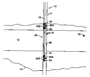
Detailed Descn_ption of the Drawings
Fig. 1 illustrates a well having a hydraulic fracture extending therefrom and
a
first embodiment of apparatus of this invention suspended therein.
Fig. 2 is a schematic of electronic components used in one embodiment .of the
apparatus of this invention.
Fig. 3 is a flowchart illustrating the principle steps of one embodiment of a
method for estimating the source of a microseismic event according to this
invention.
Figs. 4-9 illustrate six computer-generated displays used in implementing the
method of Fig. 3 for estimating the source of a microseismic event.
Fig. 10 illustrates a second embodiment of the invention used in implementing
the method of Figs. 3-9.
Detailed Description of the Invention
Referring to Fig. 1, well 10, penetrating formation I2, contains casing 11 and
has been hydraulically fractured to form vertical fracture 14 in and extending
from
formation 12. Microseismic event 20 has occurred along the plane of hydraulic
fracture 14.
Apparatus 30 of this invention has been placed at some point in casing 11
having perforations 16 using wireline 18, which may be a conventional
seven-conductor electric wireline or, as further described below, a fiber
optic cable or
copper wire for digital data transmission. Wellbore 10 may be in any selected
direction, although the description provided herein will refer to a vertical
wellbore.
Apparatus 30 comprises receiver units 32 and 34 and electronic module 36.
Electronic module 36 may also contain a pressure and a temperature sensor, a
CA 02321754 2000-08-22
WO 99/42857 PCTNS99/03606
_g_
hydrophone, a gyroscopic directional indicator or inclinometer, and other
types of
instruments. Receiver units 32 and 34 are clamped to casing 11 by clamps 32A
and
34A, respectively, with sufficient force to insure that they follow the
movement of the
casing at least up to the highest frequencies of the seismic energy to be
detected.
Standoff feet 32B and 34B may be used to increase effectiveness of the
clamping
force.
Receivers 32 and 34 preferably contain triaxial geophones or accelerometers,
e.g., three orthogonal geophones or accelerometers, although for some
applications it
will not be necessary that sensors be used for all three directions.
Preferably, the
clamping force exerted by clamps 32A or 34A is at least equal to one-half the
total
weight of the tool, but may be several times as great. Clamps 32A and 34A may
be
actuated by any source of force, but preferably are actuated by an electric
motor,
which may be controlled from the surface using well-known techniques.
Additional
receivers, similar to 32 and 34, may be added to the apparatus, each receiver
spaced
apart from the other receivers.
The distance between receiver units 32 and 34 is selected to be sufficient to
allow a measurable difference in the time of arnval of acoustic waves from
microseismic events which originate at significant distances from the well.
The
receivers are preferably at least 10 feet apart, which would be adequate to
measure
differences in arrival times of P-waves originating from a microseismic event
occurring remote from the well and significantly above or below the plane
perpendicular to the tool, but more preferably the receivers are at least 30
feet apart.
The receivers are preferably placed at opposite ends of the tool. Sinker bars
to
increase the weight of the tool for running into wells under pressure may be
added to
the tool. The presence of two triaxial receivers on the tool makes possible
determination of whether a microseismic event has occurred above or below the
tool,
and will thus resolve the 180° ambiguity present in the prior art
tools, since the
acoustic energy from the event will arrive first at the receiver nearest the
event.
The maximum distance between receivers or the length of the tool will usually
be limited by the length of the lubricator available if the apparatus is used
in a well
CA 02321754 2000-08-22
WO 99/42857 PCTNS99/03606
-9-
which will have pressure at the surface when the tool is run in or removed
from the
well. A lubricator is a device attached to the wellhead of a well for sealing
around the
wireline used to support a tool in a well. The maximum length of a standard
lubricator is about 90 feet.
Couplings 35 between receivers 32 and 34 and electronic module 36 are
preferably flexible to allow axial bending while the receivers are in the
clamped
position but are sufficiently rigid to prevent significant torsional
deformation. It is
important that the angle between the receivers along the axis of the tool be
constant
while the tool is in a well, such that the azimuth angle of each receiver be
determinable with respect to the other receiver and to a means of orienting
the tool in
a well, such as a gyroscope. To minimize transmission of acoustic energy
between
receivers, couplings 35 are preferably smaller in diameter than electronic
module 36
or receivers 32 and 34. To minimize weight and provide suitable mechanical
properties of couplings 35, couplings 35 are preferably tubes, which are
preferably
made of titanium, but may be made of any metal having suitable physical
properties.
A cable or hose comprised of strands interwoven so as to have high resistance
to
torsional deformation may also be used. The stiffness of coupling tubes 35 is
preferably selected to allow bending of tool 30 in curved wellbores when the
clamping force is applied by arms 32A and 32B. The bending allows receivers 32
and
34 to align with the wall of casing 11 and thereby to contact casing 11 over a
greater
area, which has the benefit of increasing signal strength from a source of
acoustic
energy outside the casing. The curvature of wells in intervals where the tool
is to be
run may be measured by techniques well-known in the art. This curvature, along
with
mechanical properties of the coupling tubes, is preferably used to calculate
bending of
couplings 35 when the clamping force is applied, to insure that receivers are
aligned
with the wall of the casing in a well by the clamping force.
As an example of the dimensions of the various components of a tool for use
in wellbores, receivers 32 and 34 may be 2.6 inches in diameter, electronic
module
housing 36 may be 2.25 inches in diameter, and couplings 35 may be 1.6 inches
in
diameter. In addition to the components shown in Fig. 1, the tool may have a
CA 02321754 2000-08-22
WO 99/42857 PCT/US99/03606
- 10-
"bumper sub" attached at the bottom to minimize shocks to the tool when
running in a
well.
Electronic module housing 36 includes the components of the "Downhole"
segment of the circuit schematically illustrated in Fig. 2. Inputs to the
circuit are the
signals from the six sensors in the x, y and z directions in receiver units 32
and 34 and
DC voltage signals from auxiliary instruments such as a pressure sensor, a
temperature sensor, a collar locator, or a time synchronization pulse. Each of
these
signals is fed to a voltage controlled oscillator (VCO) 42 having a selected
central
frequency. These frequencies may be in the range from about 3 kHz to about 20
kHz.
A proportional band oscillator or IRIG oscillator may be used in place of the
VCO.
The central frequency of each VCO receiving a signal from a sensor is selected
to
differ from the central frequency of other VCOs by a sufficient amount to
allow for a
bandwidth of frequencies adequate to transmit the sensor signals. Experiments
observing microseismic events during hydraulic fracturing showed that the
events
could be adequately analyzed with frequencies below about 1000 Hz. A bandwidth
of
about 5 per cent on each side of the center frequency was selected around the
central
frequency of each VCO receiving a sensor signal. The carrier frequencies are
logarithmically equally spaced for optimal filtering and channel separation at
the
surface. It was found that the amount of "crosstalk" between signals being
transmitted
over wireline greatly increased at higher frequencies, and there was
appreciable
attenuation at frequencies above 20 kHz. Therefore, it was concluded that the
highest
carrier frequency should be in the range of about 20 kHz and that precise
filtering of
signals at the surface would be required to separate each individual channel.
The
Garner frequencies and FM deviations are configured such that the intersection
of a
pass band with its nearest neighbor occurs at an amplitude at least 40 dB down
from
the amplitude at the peak frequency. Frequencies indicated for each VCO on
Fig. 2
were found to be a good compromise between minimizing crosstalk and
attenuation of
nine channels of signals transmitted over a 21,000 foot length of seven-
conductor
wireline while maintaining adequate signal resolution. Note that frequency
separation
at the lower frequencies can be reduced to only 1 kHz for use in transmitting
auxiliary
(not seismic) signals having lower bandwidth.
CA 02321754 2000-08-22
WO 99/42857 PCT/US99/03606
-11-
The VCO signal may consist of a slope-modulated triangle wave or of a
sinusoidal or other suitable repetitive signal. In the downhole circuit shown
in Fig. 2,
signals from three VCOs are fed to a mixer circuit 44 for each group of
central
frequencies. In the mixer circuit, signals are passed through a low-pass
filter to round
the waveform and attenuate odd harmonics, each channel is gained by a
calibrated
value to boost high frequencies, and the signals are added. Output from each
mixer is
fed to the primary coil of transformers 46. It was found that to avoid severe
attenuation at the higher frequencies it was necessary that transformer 46 be
low
impedance. This transformer was specifically built for data telemetry. It
preferably
has a ferrite core and is designed for operation at up to 100 kHz at a
temperature of up
to 200°C. A time-multiplexed signal is fed to the center tap of the
secondary coil of
transformer 46 receiving the intermediate frequency band, and the secondary of
this
transformer is fed to center taps of the other two transformers such that the
outputs of
all three transformers are fed to four conductors 48 of a wireline to transmit
the
1 S signals to surface.
In an alternative embodiment of the electronics, the VCO outputs as shown in
Fig. 2 are fed to a single mixer circuit, and the output of the mixer is fed
to the
primary coil of a single transformer. In this embodiment, the secondary of the
transformer feeds only two conductors of a wireline. Other conductors in the
wireline,
if any, are then available for other signals.
Electronic module 36 may also include a dynamic range compression circuit
for each geophone signal. This will make possible capturing more microseismic
events which are larger and smaller than those otherwise captured. A square
root
analog signal may be produced to compress an input voltage range of -25 V to
+25 V
to the range of -5 V to +SV, for example.
Wireline 18 of Fig. 1 exits well 10 and connects at the surface to a "surface"
electronic unit (not shown). The electronic components of the surface
electronic unit
are shown in Fig. 2. The mixed frequency signals from wireline conductors 48
feed
transformers 50, and the intermediate frequency transformer is center tapped
by a
time-multiplexed signal. The secondary of each transformer feeds Automatic
Gain
CA 02321754 2000-08-22
WO 99/42857 PCT/US99/03606
- 12-
Control (AGC} circuit 52 for each group of frequencies. The signals are then
filtered
by bandpass filter/AGC 54. The filter is very important to the success of the
FM
telemetry system. Preferably, a system of filters is used to produce a
reduction in
signal strength of at least 40 db at the intersection of neighboring
bandwidths. Digital
bandpass filters, such as the SGS Thomson TGS 8550 or 8551, are suitable for
this
purpose. Alternatively, analog filters may be used. The output of the filter
then feeds
circuit 56, which includes a frequency-to-voltage converter, consisting of a
high-speed
comparator sampling circuit to determine the period of each wave. The time
interval
digital count is converted to an analog signal via a digital-to-analog
converter. The
analog signals from each acoustic sensor and other instruments may then be
displayed
and recorded.
In an alternate embodiment of the invention, wireline 18 (Fig. 1 ) comprises a
cable having one or more fiber optic strands to enable real-time, multiplexed
digital
data transmission from the downhole acoustic sensors to the surface
electronics and
one or more conventional metal strands for transmission of power to the tool,
activation of clamp arm motors, monitoring of the collar locator sensor, and
use of a
gyroscope instrument. In this embodiment, the electronic module 36 would
include a
downhole digitizing circuit (not illustrated) to convert the analog output
signals from
the multiple acoustic sensors to digital form. The gains of this digitizing
circuit may
be fixed or possibly varied under control from a signal from the surface. The
digitized
signals would then be multiplexed and fed to a transceiver (not illustrated)
to convert
the digital electronic signal to light pulses for transmission to the surface
over the
fiber optic strands. In this embodiment of the invention, data from
microseismic
events are transmitted to the surface in real-time, without the necessity for
downhole
data storage. Thus, the tool is able to monitor for the occurrence of
microseismic
events on a continuous basis, with no periods of inactivity and no duty cycle.
At the surface, a corresponding transceiver (not illustrated) would receive
the
light pulses, convert then to digital form, and demultiplex the signal. The
digitized
output from the downhole sensors would then be directly available from the
surface
unit for storage on a digital computing system without further conversion. If
desired,
CA 02321754 2000-08-22
WO 99/42857 PCT/US99/0360b
-13-
the digital signals could be converted back to analog form and then recorded
on tape
for a continuous analog history and data archiving.
The downhole data digitizing and transmission system described above would
be a complete replacement for the frequency modulated data telemetry system
shown
in Fig. 2. Data from other conventional downhole sensors (such as a collar
locator, a
temperature sensor, a pressure sensor, and/or a time synchronization pulse)
may be
transmitted to the surface in digitized form over the fiber optic strands or,
alternatively, in analog form over the conventional metal strands.
It has been shown that a copper wire may also be used for real-time
transmission of digital data in the form of electrical pulses. Therefore, in
another
embodiment, copper wires are used instead of the fiber optic strands for
digital data
transmission. In this embodiment, high speed modem technology is used to
transmit
the digitized and multiplexed data to a compatible transceiver unit on the
surface.
Fig. 3 is a flowchart illustrating the principal steps of a preferred
embodiment
1 S of the method for estimating the source of a microseismic event, and Fig.
10
illustrates the apparatus used in implementing the preferred method. Turning
first to
Fig. 10, the apparatus 4 has three spaced-apart acoustic receivers Rl, R2, and
R3 of
x-axis and y-axis data (rather than two receivers as described above). In
addition, one
or more z-axis channels may be used to resolve event polarity. The preferred
method
may be implemented using either a frequency modulated data telemetry system,
as
described above in connection with Fig. 2, or a multiplexed digital data
transmission
system using fiber optic strands or copper wires, as described above.
Accordingly, the
electronics modules 6 and 7 in Fig. 10 may contain the appropriate equipment
for
either type of data transmission.
The method is based on the following physical properties of microseismic
signals:
~ The recorded signals consist of an initial compressional wave (P-wave)
arnval, followed some time later by a shear wave (S-wave) arrival.
CA 02321754 2000-08-22
WO 99/42857 PCTNS99/03606
- 14-
~ The P-wave direction is aligned with a vector at the receiver pointing at
the
source of the microseismic event, and the S-wave is orthogonal to the
P-wave vector. Thus, for sources away from the wellbore, a hodogram or
x-y crossplot of a time windowed portion of the P-wave generates an
ellipse whose major axis is aligned with the azimuth to the source, and the
hodogram of the S-wave forms an ellipse whose major axis is
perpendicular to the line from the receiver to the source location.
~ The P-wave propagation speed (or "slowness") is aP, and the S-wave
slowness is as (expressed in units of traveltime per unit length). The
P-wave propagates faster, so aP is less than as. For P-wave and S-wave
traveltimes of tP, and ts" respectively, and distance D, from the source
location 5 to receiver Rl, the traveltimes may be calculated from tP, = D,aP
and tS, = D,as. Similar relationships hold for traveltimes tP2 and tS2 (and
distance D2) for receiver R2 and for traveltimes tP3 and ts3 (and distance D3)
IS for receiver R3. Various methods known in the art may be used to
calculate the effective average slowness of P-waves and S-waves in
layered earth media of variable properties.
Persons skilled in the art will understand that the method is preferably
practiced using a suitably programmed digital computer. Such persons could
easily
develop computer software for performing the method based on the teachings set
forth
herein.
The following description will illustrate implementation of the inventive
method using an interactive, graphical computer software code that has been
designed
to be interpretive and flexible in its use. The code consists of six basic
displays that
are used interactively to examine the event data, initialize a solution, and
then refine
that estimate to determine the most likely source location. However, other
implementations of the inventive method are possible. Accordingly, the
following
description is intended to be illustrative of the method only and is not to be
considered
as limiting the scope of the invention.
CA 02321754 2000-08-22
WO 99/42857 PCT/US99/03606
-15-
The six basic displays of the interactive software code are illustrated in
Figs. 4-9. In each of these figures, reference numeral 150 denotes the outer
border of
the computer display screen. It will be understood that in actual practice
these six
displays utilize a number of different colors to aid the user in identifying
and
5 interpreting the data. The six basic displays have certain features in
common. For
example, there is a common set of text in the upper left corner of each
display. In this
text, "azim 121 w" means that the azimuth to the current estimated source
location is
N 121° E, and the event is on the west side of the well (azimuth is
calculated from 0°
to 179° corresponding to standard compass directions, and east "e" and
west "w" are
used to indicate the side of the wellbore where the event occurred); "x/z
60/2265"
means that the current estimated source location is at a depth of 2265 feet
and at a
range of 60 feet from the wellbore; "e/n -51/31" means that the current
estimated
source location is 51 feet to the west (negative easterly value) and 31 feet
to the north
of the wellbore; "i/n 1008/160" means that the current setting for the
windowed
15 displays is to start the window at an index of 1008 and display 160 time
samples of
each data series; "zh2o 0" is a measure of the distance along the wellbore
from
receiver Rl to a hypothetical source location used to investigate the
possibility of
energy propagation along the wellbore at the acoustic velocity of water or
steel;
"rms 0.36 0.18 1.17" means that the root-mean-square value of the data (a
measure of
20 standard deviation) is 0.36 for receiver R1, 0.18 for receiver R2, and 0.17
for receiver
R3; "pk 1.7 1.5 1.6" means that the peak magnitude of the data is 1.7 for
receiver Rl,
1.5 for receiver R2, and 1.6 for receiver R3. The "PP", "SS", "P 1 S", "P2S",
and
"P3S" notations, each followed by three rectangles, are used to indicate that
the time
difference fixes (discussed below) have been set if the respective rectangle
is filled
25 with the color of the corresponding loci of points in the "Solution
Display" (Fig. 8).
Turning now to Fig. 3, the x and y data corresponding to a microseismic event
from each of the three receivers are read into computer memory from storage
(step
100) and then are transformed to north and east earth coordinates 102. This
transformation is accomplished by coordinate rotation through an angle
determined by
30 the tool clamping arm azimuth and geophone orientation using well-known
trigonometric relationships. While not absolutely necessary for the method,
SUBSTIII~I'E SHF..~E~" (RUL.S 26)
CA 02321754 2000-08-22
WO 99/42857 PCTNS99/03606
- 16-
transformation of the data to north and east earth coordinates permits the
source
location to be determined with respect to known surface directions.
Fig. 4 illustrates the "Event Display" which is used to view the data as the
user
scrolls through a file of recorded events. Time series data recorded by each
of the
three receivers, R1, R2, and R3, are shown transformed to northerly and
easterly
components. Each of the three plots consists of two traces, a P-wave trace and
an
S-wave trace, for the receiver in question. Note that the duration of the
microseismic
event shown in Fig. 4 is less than 300 milliseconds.
On entry to the Event Display, the text data in the upper left corner
corresponds to an initial event location. The text data on the Event Display
(and all
other displays) is continuously updated as the event analysis proceeds. The
initial
position may be set by the program to the location of the previous event, or
perhaps to
some arbitrary location such as a position due east, at the depth of the top
receiver,
100 feet from the well. The initial solution location is not critical to the
method, but if
the new event is located near a prior event then proper initialization may
expedite
solution of the current event.
Recorded events are examined using the Event Display to determine if the
recorded signals are likely to be microseismic in origin (some recorded
datasets are
not) or if the event appears to be interpretable. There are events that are
recorded that
produce significant signals at only one receiver, and these are generally
found to be
uninterpretable events that are likely to have been generated near the
wellbore. The
user proceeds to analyze a particular event if the event appears to be
interpretable.
The next step of the method is to initialize the solution (reference numeral
104
in Fig. 3). The results of this step are displayed in a "Cursor Display," an
example of
which is shown in Fig. S. In Fig. 5, windowed portions (e.g., from 75 to 125
milliseconds) of the horizontal component data are shown with no time shifts
applied.
Cursors 200, 202, and 204 are used to identify P-wave arrival times, and
cursors 206,
208, and 210 are used to identify S-wave arrival times. These cursors are
defined
using the current source location estimate shown in the upper left comer of
the display
CA 02321754 2000-08-22
WO 99/42857 PCTNS99/03606
-17-
and the associated traveltimes tP,, ts,, tPZ, t~, tP3, and ts3 calculated as
described above.
Because the traveltime differences are measured, and the instant of the event
is
unknown and must be estimated, there is one degree of freedom corresponding to
one
cursor that must be assumed or positioned manually. This cursor is known as
the
"anchor cursor." The solution is initialized by selecting one of the P-wave or
S-wave
an-ivals on one of the receivers as an anchor cursor location (step 106 on
Fig. 3). By
default, the P-wave arrival time of the largest amplitude event is selected
for the
anchor, but any of the other P-wave or S-wave arrivals may be used if desired.
Movement of the current source location will be reflected by changes in the
remaining
10 five free cursors. The position of the anchor cursor does not change as the
source
location is varied. Hodogram crossplots of the windowed P-wave and S-wave data
shown on the left side of the Cursor Display are used to adjust the source
azimuth
angle (step 108 in Fig. 3).
The current source location is shown both in the text and in graphical form,
depicted in the x-z plane by a black square with lines to the tool image on
the left
border of the time series portion of the display. The source location may be
varied in
four directions (up, down, left, right). As the source location is varied in
the Cursor
Display, the P-wave cursors 200, 202, and 204 and the S-wave cursors 206, 208,
and
210 and hodogram images (described below) will change to reflect changes in
the
acoustic traveltimes from the updated source location to each receiver.
Also shown in Fig. 5 are cursors 212 and 214 showing possible arnval times
of near-wellbore events that might be traveling at the velocity of seismic
waves in
water (about 4800 ft/sec) or in steel (about 17,000 ft/sec). The Cursor
Display allows
for screening of such events.
25 The azimuth angle to the source location may not be well determined when
entering the Cursor Display. It may be possible to update the azimuth from
this
display using the two hadograms along the lower left side of the display.
These are
small versions of the Horizontal Hodogram Display (Fig. 7) discussed below.
The
hodogram crossplots are updated for a time window about each of the P-wave and
CA 02321754 2000-08-22
WO 99/42857 PCT/US99/03606
-18-
S-wave cursor locations corresponding to the time shifts applied in the
Alignment
Display (Fig. 6) discussed below.
From the Cursor Display, time difference fixes may be selected as described in
more detail below. This task is essentially one of recognizing that, at the
current
source location, one of the fifteen P-P, S-S, or P-S time differences are
approximately
matched and ready to be "fixed."
In the next step of the method (step 110 in Fig. 3), the solution is refined.
This
comprises iteratively refning the window selection and rotating the azimuth
angle
(step 112) and adjusting the source location to maximize alignment of P-P, S-
S, and
P-S waveforms and fix time differences (step 114). Two displays, an "Alignment
Display" (Fig. 6) and a "Horizontal Hodogram Display" (Fig. 7) are used to
refine the
solution.
The Alignment Display (Fig. 6) is used to refine the solution by seeking the
maximum degree of alignment of the time-shifted waveforms. By applying the
appropriate time shifts to remove the calculated time differences, the
waveforms may
be more closely matched by aligning the early portions of each P-wave and S-
wave
arrival component.
To prepare for the Alignment Display, the horizontal component data are
transformed from easterly and northerly components to respective components
along
perpendicular P and S axes. The P-axis is oriented along the current azimuth
to the
source, and the S-axis is oriented perpendicular to the direction to the
source. The P
and S axes thus form a right-handed coordinate system obtained by coordinate
rotation through the azimuth angle, and the sensor response in easterly and
northerly
components may be represented in the P and S coordinate system. P-wave energy
should be represented primarily by the response along the P-axis, and S-wave
energy
should be mostly captured along the S-axis. Due to mode conversions and
leakage,
some P-wave energy is usually found on the S-axis, and vice versa.
CA 02321754 2000-08-22
WO 99/42857 PCT/US99/03606
-19-
In the Alignment Display, the P-axis data are plotted with inverse time shifts
using the P-wave traveltimes from the current source location to each
receiver. The
S-axis data are plotted using the respective inverse S-wave time shifts. These
time
shift values are obtained from an internal array of traveltimes between each
grid point
in the x-z plane and each of the receivers, for both P and S components.
Traveltimes
may be calculated by one of several methods known by those skilled in the art.
Alternatively, the traveltime differences between each value and the minimum
traveltime of the set corresponding to those at a particular grid point may be
used to
inverse time shift the data. This relative time shift implementation is
preferred
because it uses computer resources more efficiently.
In the following discussion, the notations P; and P~ correspond to the P-axis
data after inverse time shifting by amounts determined by the P-wave
traveltimes
between the current source location and the i'~ receiver and j"' receiver,
respectively.
Similarly, the notations S; and S~ correspond to the S-axis data after inverse
time
shifting by an amount determined by the S-wave traveltimes between the current
source location and the i~' receiver and j"' receiver, respectively. Because
the S-wave
is generally slower than the P-wave, the S-wave inverse time shift usually is
greater
than that for the P-wave, resulting in a relative shift in the S-wave energy
to the left in
the Alignment Display.
The time series data shown on the right side of the Alignment Display is
divided into five sections consisting of the following crossplots proceeding
from top
to bottom: P;-P~, S; S~, P,-S~, Pz-S~, and P,-S~. Movement of the current
source location
causes the waveforms to be shifted as the time shifts are updated for the new
source
location. This facilitates relocation of the source until a desired alignment
is obtained.
The optimal source location will be that which achieves the greatest degree of
alignment of the initial energy on each waveform in the Alignment Display. The
arrival time differences may be fixed from this display for purposes of
interpreting the
most likely source location in the "Solution Display" (Fig. 8), discussed
below. The
process of "fixing" a time difference consists of visually selecting an
arrival time
difference (typically using peak-to-peak time differences, but optionally
CA 02321754 2000-08-22
WO 99/42857 PCT/US99/03606
-20-
inception-to-inception time differences), recognizing that an alignment has
been
achieved, and selecting a waveform arnval time difference match to be saved.
Once a
time difference has been fixed, a loci of points corresponding to that time
difference
will be plotted on a "Solution Display" (see Fig. $), as further described
below.
Because the data in the Alignment Display are prepared as the respective
component values along the directions parallel and perpendicular to the source
location, revisions to the azimuth estimate will cause changes in the P and S
data
series shown in the Alignment Display. The small hodograms on the lower left
side
correspond to the data windows on the right side. The upper P hodogram is the
data
corresponding to the P-wave time shifts of the top section on the right, and
the lower
S hodogram is the data window of the S-wave time shifts of the next section.
In the
example of Fig. 6, the orthogonal rotation of the energy from the first P-wave
data to
the later S-wave data is evident. This display may be used to refine the
azimuth angle,
or alternatively the larger version in the Horizontal Hodogram Display (Fig.
7) may be
used.
Fig. 7 is a "Horizontal Hodogram Display" that may be used to determine the
azimuth angle to the source. The graph on the left side consists of the
horizontal
signals plotted as northerly versus easterly components with P-wave inverse
time
shifts that correspond to the top section of the Alignment Display (Fig. 6).
Similarly,
the right side shows the horizontal components with inverse time shifts for
the S-wave
traveltimes. These windows thus consist of the horizontal response, inverse
time
shifted for the respective waveform type (P or S). By using the time-shifted
components, simultaneous matching of azimuths at all receivers is facilitated,
and also
both the P-wave and S-wave arnvals may be simultaneously fit as suitable for
the
respective directions of the arrivals.
In Fig. 7, additional statistics are available to indicate the results of
numerical
regression on the data within the window, relative to the objectives of
fitting an ellipse
in the direction of the source (P-wave) or orthogonal to that direction (S-
wave). In the
example shown in Fig. 7, for an azimuth to the source of 123°, the P-
wave data should
be so oriented and the S-wave data should be oriented along the 33°
direction, as
CA 02321754 2000-08-22
WO 99/42857 PCT/US99/03606
-21 -
indicated at the top of the text blocks above each hodogram. The individual
regression results for the data for each receiver are shown, with P-wave time
window
regression results of 127° (RZ = 0.94) for receiver R1, 133° (RZ
= 0.98) for receiver
R2, and 111 ° (RZ = 0.99) for receiver R3. The regression results and
RZ values are
determined using a special regression procedure developed for hodogram
analysis.
This method is superior to standard linear regression in Cartesian coordinates
when
the problem is most naturally presented in polar coordinates. For all possible
azimuth
angles a from 0° to 179°, the following calculation is performed
for the data within
the specified time window from index p to q:
Z
u;
R '-p for u~ = n; cosy + e; sins
2=
~i12 +Vz V; =n; since -e; cOSa
~°p
The variable u; corresponds to the projection of the horizontal sensor
response along
the azimuth angle a, and the variable v; is the projection orthogonal to that
direction.
The n; and e; variables correspond, respectively, to the northerly and
easterly
components of the horizontal sensor response. The value of a that maximizes Rz
is
-'15 the solution to the regression, since the R2 statistic measures the sum
of squares along
the azimuth direction relative to the total sum of squares. This value is
maximized for
the most likely azimuth direction.
In a similar manner to that for the P-wave hodogram, a regression analysis
may be carried out for the ellipse of the horizontal response corresponding to
the data
after inverse time shifting for the S-wave arrival. Since it is not assured
that the
P-wave has decayed by the time of the arrival of the S-wave, there may or may
not be
a good regression fit obtained over the S-wave hodogram shown on the right
side of
Fig. 7. Field test data have shown reasonably good results for the S-wave
hodogram,
in part because the S-wave amplitude is usually larger than that of the P-
wave.
Fig. 8 is the "Solution Display." The right side of the display consists of an
image of the x-z half plane, oriented along the azimuth angle to the source
and
CA 02321754 2000-08-22
WO 99/42857 PCT/l3S99/03606
-22-
passing through the wellbore axis. The wellbore lies along the left edge of
this plane,
and a tool image is also shown on this axis. The lateral distance x and depth
z of the
current source location are plotted in the plane, with lines to the top and
bottom tool
receivers as may also be found in Figs. 5 and 6.
The solution may be developed by building up a series of arrival time
alignments, "taking a fix" as in the terminology of marine navigation, and
plotting the
corresponding loci of points for each such fix. The grand intersection of
these loci
will determine the most likely source location for the event.
In the art of maritime navigation, the position of a ship may be determined by
measuring the compass bearing of two or more buoys or shore objects and
plotting
lines on a chart through such objects at the measured angles. The intersection
of the
lines defines the ship location. In an even closer analogy, the location of a
ship by the
Loran method consists of determining two or more loci of points on the chart
that
correspond to measured time differences on different radio frequencies. The
ship
location is at the intersection of these loci. A similar approach is used in
this
microseismic data analysis, wherein 15 arnval time differences may be used to
determine up to 15 loci of points.
Initially there are no loci shown in Fig. 8 for an event. Arrival time
differences may be fixed from the Cursor Display (Fig. S) and the Alignment
Display
(Fig. 6). As these time differences are determined, returning to the Solution
Display
(Fig. 8) will show progressively more loci corresponding to those that have
been set.
Lines emanating from the wellbore will be plotted for constant P-P or S-S time
differences, and circular loci will be shown for constant P-S time differences
(step 116
in Fig. 3). When the user has set a sufficient number of time differences such
that
there is a distinct intersection as shown in Fig. 8, the event location may be
considered
to have been determined in the x-z plane.
In this display, color coding is preferably used to show the number of loci
intersections at each grid point. To obtain a location estimate with high
accuracy, it is
important to achieve a sufficient mixture of loci intersection. Although only
two P-P
CA 02321754 2000-08-22
WO 99/42857 PCT/US99/03606
- 23 -
or S-S intersections are required to determine a source location, the range
estimate
will not be very precise unless the event is relatively near the wellbore. One
or more
P-S intersections is useful to develop a circular loci that intersects these
linear loci
with more precision. Analogously, the location estimate from two P-S loci will
be
S significantly improved by intersection with one or more P-P or S-S loci.
On the left side of the Solution Display are two hodogram images, one for the
P-wave window and one for the S-wave window. These are small versions of those
shown in the Horizontal Hodogram Display (Fig. 7) and are available to confirm
proper azimuthal orientation.
Finally, Fig. 9 is a "Vertical Hodogram Display." In this display, the
horizontal x component along the azimuthal direction is the abscissa, and the
vertical
z response is the ordinate. The P-wave traveltimes have been used for inverse
time
shifting so that the window selection corresponds to the top section of the
Alignment
Display (Fig. 6).
A line representing the inclination angle from the receiver to the current
source
location is also shown in this display. This line will be oriented "up" or
"down"
depending on which side of the wellbore the event is located. The most likely
orientation is obtained by achieving the best fit between this inclination
line and the
hodogram of the data in the x-z plane.
The source location may be varied between the west and east sides of the
wellbore, resulting in a flip-flop of the inclination line from the receiver
to the current
source location. The window frame may also be modified from this display until
the
event location ambiguity is resolved (step 118 in Fig. 3), for the
calculations in the
other displays allow for two possible source locations on opposite sides of
the well.
Note that in the current tool configuration, the z channel from only the top
receiver is
recorded. With additional z channels, further confirmation of source location
would
be established.
CA 02321754 2000-08-22
WO 99/42857 PCT/US99/03606
-24-
Although the flowchart in Fig. 3 indicates an anticipated order for the
various
operations, it will be understood that the software tool should be designed to
facilitate
iterating between different displays to obtain the most effective source
location
solution.
The procedure for estimating the location of a microseismic event source has
been described heretofore. The apparatus and method of this invention are also
applicable to a continuous acoustic wave from a source which is to be located.
In
such cases, a data window is selected, consisting of a selected number of time
samples. The same procedure is then followed as set out above.
When the apparatus or method of this invention is applied to detection of the
extent of a hydraulic fracture, the apparatus may be placed at a single
location in a
wellbore from which the fracture extends or it may be placed at multiple
locations and
microseismic events detected from each location. The apparatus may be placed
in the
well from which the fracture extends or it may be placed in an offset well.
If there is particular interest in determining if a hydraulic fracture has
been
extended out of the zone of fluid injection in an injection well, the
apparatus may be
placed at one or multiple locations near a possible barrier to fluid flow, and
may be
used to determine if microseismic events occur on the side of the barrier
opposite the
injection zone, using the techniques described above.
It has been observed that signals from microseismic events can be received
through multiple strings of pipe in a well. For example, in a well having 5
1/2-inch
casing suspended in 13 3/8-inch casing and extending only partially to the
bottom,
signal strength from explosion of a small test charge was only slightly
attenuated
when the apparatus was clamped inside the 5 1/2-inch casing rather than in the
13 3/8-inch casing. Therefore, the apparatus of this invention may be placed
inside
multiple concentric pipes and the method described above may be used to
determine
the source of microseismic events.
CA 02321754 2000-08-22
WO 99/42857 PCT/US99/03606
-25-
It will be appreciated that while the present invention has been primarily
described with regard to the foregoing embodiments, it should be understood
that
variations and modifications may be made in the embodiments described herein
without departing from the broad inventive concept disclosed above or claimed
hereafter.