Note: Descriptions are shown in the official language in which they were submitted.
CA 02321800 2005-05-26
1
Method and arrangement for coating a moving web of paper
or board
The present invention relates to a method for two-sided
coating of a moving paper or board web with at least one
coat layer.
The invention also concerns an arrangement suited for
implementing said method.
In the coating of a paper web, to a base sheet
manufactured in a paper machine is applied a coating mix
layer that is smoothed to a desired thickness. The
coating mix is made by slurrying coat solids into water
and. the web is dried after coat application prior to its
entry into the subsequent finishing steps. The coater
machine can be placed either directly after the paper
machine manufacturing the base sheet, whereby the
arrangement is called an on-line layout, or
alternatively, as a separate section to which the wound
base sheet rolls are transported to be unwound there and
coated in an entirely separate off-line coater.
The production capacity of a coater machine is chiefly
dictated by its width, web speed and reliability of the
machine function. The most important factor affecting the
functional reliability is the number of web breaks that
should be kept as small as possible. Today, paper
machines and coaters are already very wide, up to about 8
- 10 m, and a greater width is extremely difficult to
achieve due to a number of reasons including the greater
bowing of rolls. Hence, the productivity of paper
machines and coaters is preferably improved by elevating
the web speeds in these machines. However, at higher web
speeds also the web run in the coater becomes more
difficult to control. One major problem is caused by the
CA 02321800 2005-05-26
2
boundary air layer travelling on the rapidly moving web
that tends to detach the web from its support rolls. If
the web loses its contact with the support rolls, control
of web run becomes impossible and, respectively, loss of
web contact with the backing roll at the applicator
causes bagginess and problems in the application and
smoothing of the applied coat. Hence, the control of web
run in fast coating machines must be accomplished by
means different from those used in prior-art machines.
The: most common technique is to use an at least partially
supported web run through the machine. When the web is
passed supported by an air-permeable wire or belt, the
formation of an air layer between the web and the support
wine or belt is prevented, thus allowing the web to stay
in an intimate contact with the surface of the support
means. Further, a supported web run is an effective
measure to reduce the number of web breaks due to
variations in web tension, because tensioning of the web
itself is not needed.
Instead of a wire, an air-cushion-type support means can
be used in a coater for guiding the web run after
coating, thus avoiding physical contact of any mechanical
elements with the web. However, the air-cushion supported
web guidance requires a substantially bulky free space
particularly in the vertical dimensions of the machine,
because the web cannot be guided by an air-cushion
turning means in substantially sharp bends, particularly
not through a sequence of sharp bends. Air-
cushionsupported web run also needs dedicated means for
threading the web trailing end through air dryers and
air-cushion turning devices, because air dryers and air-
cushion turning devices are incapable of pulling the web
forward, but rather, the web must be drawn through the
dryer units by means of pulling roll group or similar
pulling means located after the dryer section and capable
of maintaining a sufficient tight web draw. However, also
I ~ I I ~ I
CA 02321800 2005-05-26
3
this arrangement involves the risk of web breaks due to
variations in web tension.
In the manufacture of a coated paper grades, the current
trend is to use a base sheet as thin as possible, because
the quality of the finished paper can be improved by
coating in a better manner than by increasing the
thickness of the base sheet and, moreover, the cost of
the coat is appreciably lower than that of the base
sheet. Obviously, the strength of a thinner base sheet is
much lower and, hence, the risk of web breaks
particularly when the base sheet becomes wet in
application of the coating will be the greater the
thinner base sheet is used. Hence, the choice of a
suitable application method is a particularly vital
question in machines running at high web speeds and
making thin paper grades. The optimal coating techniques
for fast machines are such applications methods as film
transfer application, jet application and spray
application which impose a minimal stress on the web and
cause a minimum penetration of coating mix and moisture
into the web. Particularly advantageous herein is that
these application methods at best can apply only so much
coat to the web that no doctoring after application is
required. Obviously, the stress of application on the web
is thus minimized. When this kind of an application
method causing a minimum stress on the web is combined
with, e.g., an entirely belt- and wire-supported web run
through the entire machine, the system can be made to
operate extremely reliably even at high web speeds.
It is an object of the present invention to provide a
method capable of permitting a substantial speed increase
of a paper web coating machine, yet simultaneously
keeping the vertical and machine-direction space
requirements of the machine within reasonable dimensions.
i . I . i ~ I
CA 02321800 2005-05-26
4
They goal of the invention is achieved by way of
advantageously using a film transfer coater for applying
the coat to the web and then passing the web to a dryer
cylinder group over a wire-supported air-cushion
cylinder, thus making it possible to support the web over
its entire run from application to the end of drying.
According to a preferred embodiment of the invention, the
assembly also includes a belt calender and a belt-
supported winder, whereby the web is essentially support-
ed over its entire run from the unwinder or paper machine
exit end to the winder.
By virtue of the invention, the coater design can be made
very compact and the web can be easily passed from the
support elements of one paper machine section to the
next. The web run is entirely supported except for a
short length at the web tension measurement equipment,
thus allowing the frequency of web breaks to be reduced
to a minimum. The web is coated in a film transfer coater
and then passed to a first dryer member which is a
cylinder with an air-cushion function. On the air-cushion
cylinder, the web surface is dried by air ejected through
the cylinder shell, while the web is simultaneously
supported by the wire and guided by its edges resting
against the cylinder rims. Using belt supported top-side
film transfer coaters, the coat can be applied to the
upper surface of the web, whereby the length of web run
is 'minimized. With the help of the air-cushion cylinder,
the web can be passed via a very uncomplicated path to
the dryer cylinders without marring the applied coat, yet
keeping the length of web run at a minimum. The web is
dried finally in a wire-supported dryer cylinder section
and subsequently passed on the support belt of the next
coater section. Here, the other side of the web is coated
by film transfer applicators and the web is passed over
an air-cushion cylinder to the next dryer cylinder
section in the same manner as described above, whereby
CA 02321800 2005-05-26
the: construction and web run of the second coater/dryer
section becomes very uncomplicated, too. The equipment
ma~~ be very advantageously combined with a belt-supported
cal.ender and a belt-supported winder, whereby the web
5 will run fully supported all the way starting from its
entry to the coater and ending at the winder.
In the following, the invention will be examined in
greater detail by making reference to the appended
drawings, in which
Figure 1 shows schematically an embodiment of a coater
according to the invention;
Figure 2 shows schematically the principle of web
spreading by means of the wire width control;
Figure 3 shows schematically one technique of wire width
narrowing; and
Figure 4 shows schematically another technique of wire
width narrowing.
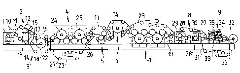
The coater machine shown in the first diagram comprises
an on-machine applicator, whereby the paper web passed
thereto is first introduced to an intervening calender 1,
from which the web is passed forward in the machine.
In the machine, the web is first passed to a first film
transfer coater 2 in which the coat is applied to the top
side of the web. From the film transfer coater 2, the
coated web is passed over an air-cushion cylinder 3 to a
dryer cylinder section 4. From the dryer section 4, the
web is further passed to the next film transfer coater 5
in which the bottom side of the web is coated. After the
bottom side of the web is coated, the moist web is passed
to a second air-cushion cylinder 6 and further to a
second dryer cylinder section 7. The dried web is next
CA 02321800 2005-05-26
6
passed onto a first calender belt of a belt calender 8
and., supported thereon, into the first calender nip,
therefrom onto the second calender belt and into the
second calender nip. From the calender 8, the web is
passed to a belt-supported winder 9.
The web is passed to the coater from a support belt 10 on
which the web runs when it is passed to the support belt
11 of the first film transfer coater.
The first coater station 2 is a top-side film transfer
coater in which the upper roll 12 of the coater acts as
the applicator roll. The support belt 11 passes over a
lower roll 13 which serves as the backing roll of the
film transfer coater. In this manner, the web can be
guided maximally smoothly from the intermediate calender
or post-dryer section of the paper machine, or in an off-
line coater machine, from the unwinder, to the film
transfer coater and, therefrom, forward along a maximally
straight path. From the support belt of the film transfer
coater 2, the web runs unsupported over a short distance
to the support wire of the air-cushion cylinder. On the
web passage from the support belt 11 of the film transfer
coater to the support wire 14 of the air-cushion cylinder
is adapted a scanning beam 15 of web tension measurement
equipment based on sensing with air-jet injection for
measuring the web tension and its tension profile,
whereby these data are used for controlling the draw
between the film transfer coater and the subsequent
equipment. A draw-based web tension control scheme is
necessary because the web dimensions change with the
variation of the web moisture content during coat
application. The web meets the support wire of the air-
cushion cylinder at a guide roll 17. Between this guide
roll 17 and the air-cushion cylinder 18 is adapted a web
spreading device 16 as shown in more detail in Fig. 2.
CA 02321800 2005-05-26
7
Web elongation due to the wetting of the web at the
coater may be compensated for by controlling the machine
draws and web tension. However, the increase of web width
must be compensated for by means of separate devices
capable of spreading the web, thus keeping the web
smoothly adhering to the support wires and belts. When
the: web is passed from the coater station to the support
wire as in the exemplifying embodiment illustrated in
Fig. 1, the web spreading can be implemented by narrowing
and spreading the support wire 14. This is accomplished
by means of passing the web in the coater station from
the support belt 11 to the support wire at the wire-
narrowing bowed roll, more exactly, by adapting the web
to meet the support wire exactly at the wire-narrowing
roll. The wire-narrowing roll 19 may be either a
conventional reverse-mounted spreading roll 19 of the
type shown in Fig. 3 comprised of roll segments mounted
on a bowed shaft, or alternatively, a so-called worm roll
of the type shown in Fig. 4, whereby the contoured sur-
face of the roll provides the wire-narrowing effect. At
the wire-narrowing roll 19, the wire width is narrowed
due to the cross-machine elasticity of the wire, thus
allowing the web to meet a narrowed support wire. When
leaving the wire-narrowing roll, the wire tends to
recover its normal width, whereby also the web is spread
correspondingly. Next, the support wire with the web
travelling thereon can be passed to a conventional
straight guide roll, after which a separate spreading
roll can be additionally used if so required to
compensate for web spreading. As the moisture content of
the web is reduced in later sections, the web width
becomes narrower thus causing the web to shrink with
respect to wire, whereby no creasing or separation of the
web from the support wire can occur in the same manner as
takes place with the increase of the web width.
In the support wire used for spreading the web, the
available spreading capacity should be at least 0.5
CA 02321800 2005-05-26
g
preferably greater than 1 %, combined with a low
elasticity. The wire should also offer a good adherence
to the web and the wire-narrowing roll, which means that
the: coefficient of friction on the wire surface should be
high. If the wire is used as a dryer wire, it must have
good resistance to high temperatures and, further, the
aerodynamic properties of the wire need to be good at
high web speeds. Obviously, the wire should be easily
guidable, it may not crease when passing over the wire-
narrowing roll, and it should have a sufficiently long
service life. The meeting point of the web with the wire
must be arranged to fall on the narrowed portion of the
wire.
Subsequent to coating, the first dryer member in the
layout according to the invention is an air-cushion
cylinder 18. This device comprises a pressurized cylinder
whose shell is perforated with holes through which hot
air or steam is injected outward and against which the
running web is supported by the wire 14. The coated top
side of the web faces the air-cushion cylinder, while the
uncoated bottom side of the web is supported by the wire
14. With the help of the air jets injected radially
outward from the air-cushion cylinder 18, the web runs
noncontactingly over the surface of the air-cushion
cylinder 18 and thus the web is contactingly supported
but for a short machine-direction length by its edges
that are pressed by the wire 14 against the end deckles
of the air-cushion cylinder 18.
As can be seen from Fig. 1, the web path from the film
transfer coater 2 to the air-cushion cylinder 18 is very
short and straight. In a similar fashion, the web can
also be passed to the next dryer member practically in
the same horizontal plane as it approaches the air-
cushion cylinder. Thus, the web meets and leaves the air-
cushion cylinder in the same horizontal level.
., CA 02321800 2005-05-26
9
The web is passed from the wire of the air-cushion
cylinder by means of a pick-up roll 22 to the support
wine 23 of the dryer cylinder group. The pick-up roll 22
is adapted to rest against the wire 14 of the air-cushion
cylinder 18 and, respectively, against the wire 23 of the
dryer cylinder group 4, and the web is passed from the
wire 14 of the air-cushion cylinder 18 about the pick-up
roll 22 to the wire 23 of the dryer cylinder group 4.
Said dryer cylinder group 4 includes said wire 23 running
over guide rolls 27, smooth web-contacting dryer
cylinders 26, air-permeable air-impingement dryer
cylinders 24 and high-velocity hoods 25 adapted about
said air-impingement dryer cylinders. The basic members
of the dryer group 4 are two air-impingement dryer
cylinders 24 having smooth web-contacting dryer cylinders
26 adapted to their both sides. All the dryer cylinders
are so located with regard to each other that the wire
with the web supported by it will be wrapped by over 180°
about each cylinder. After being partially dried at the
air-cushion cylinder 18, the web is next passed to the
first smooth dryer cylinder 26, where the support wire
presses the coated side of the web against the surface of
the smooth dryer cylinder 26. Here, the hot cylinder
evaporates the moisture of the web and its smooth surface
partially smooths the surface of the coat adhering
thereto. Next, the wire 23 and the web running supported
by the same are passed to a first air-impingement dryer
cylinder 24 having high-velocity hoods 25 adapted there-
about. The interior of the hoods 25 is provided with a
plurality of nozzles serving to blow a drying gas at a
high velocity onto the web running on the wire 23.
Depending on the moisture content of the web and other
factors, hot air or superheated steam may be used as the
drying gas. The dryer cylinder group comprises four
smooth-surface dryer cylinders 26 and two larger-diameter
air-impingement dryer cylinders 25. The larger-diameter
dryer cylinders are placed between the smooth dryer
cylinders so that the web can be passed first to one
CA 02321800 2005-05-26
smooth dryer cylinder, then to one large-diameter dryer
cylinder 24 and further to a second smooth dryer cylinder
26. The large-diameter dryer cylinders 24 may be either
suction cylinders, which are permeable to the drying gas
5 and brought to a vacuum, or alternatively, air-
impingement dryer cylinders having a surface so grooved
as to allow the drying gas impinging thereon to escape
via. the backside of the wire 23. The smooth-surface
cylinders are mounted in the same horizontal plane so
10 that the height at which the web runs over these
cylinders is located close to the web meeting/leaving
point on the air-cushion cylinder surface, whereby the
length of web run is reduced to the shortest possible and
the coater space requirement in the vertical direction
can. be minimized.
After the web supported by the wire 23 of the dryer
cylinder group 4 has passed through the entire dryer
cylinder section it is delivered supported by the wire 23
to the support belt 11 of the next coater station 5.
Here, coat is applied to the other side of the web, that
is, to the web bottom side which remained uncoated after
leaving the preceding coater station 2. Next, the support
belt 11 of the coater station 5 runs about the upper roll
of the film transfer coater, whereby said upper roll acts
as the backing roll of the coater. Herefrom, the web is
passed to the dryer section of the line which is other-
wise similar to that of the preceding coater section
except for having the support wires and belts adapted to
pass above the section members and, respectively, having
the larger-diameter dryer cylinders 24 of this second
dryer cylinder group 7 adapted below the smooth-surface
dryer cylinders 26. Also herein, the smooth dryer
cylinders are placed in the same horizontal plane and the
meeting/leaving point of the web on the air-cushion
cylinder is located in the vertical direction close to
the plane in which the web runs over the smooth
cylinders.
. CA 02321800 2005-05-26
11
From the dryer group 7, the web is passed to a belt
calender 8 comprising two support belts and two calender
nips. Each of the calender nips comprises one calender
roll 28 with a cooperating backing roll 29. The calender
belt 30 wraps about the backing roll, whereby the web
passed to the calender belt travels through the nip
between the calender roll 28 and the calender belt 29. In
the first calender nip, the calender roll is placed above
the calender belt, and in the second calender nip,
respectively, the calender roll is placed below the
calender belt 30. Thus, both sides of the sheet will be
contacted with both the calender roll and the calender
belt during calendering. In a similar manner as in all
preceding sections, the web is passed from one nip to the
next so supported by the calender belts that the web run
takes place supported for its entire length.
The winder 9 is of an entirely belt-supported type in
which the web is passed supported by a support belt 31 up
to the paperboard roll 32. The winder comprises a winder
cylinder 33 and a winder mandrel 34 forming a nip through
which the web is passed onto the mandrel. The winder
further includes a transfer device 35 for bringing a new
mandrel into a nip contact with the winder cylinder 33
when the paper or board roll wound about the previous
mandrel is full. The support belt 31 of the winder 9
passes via the last nip formed by the calender belt 30 in
calender 8 and then travels to the winder cylinder 33.
The change of the roll mandrel 34 takes place by moving
the guide roll 36 of the support belt 31 so that the web
is supported during the entire change-over operation by
the support belt 31 and all the time passes through the
nip between guide roll 36 and the paperboard roll 32.
Simultaneously a new roll is brought into contact with
the web supported by the support belt 31 and the web is
severed so that it starts to wind up about the new roll
CA 02321800 2005-05-26
12
mandrel 34. This type of winder is disclosed in F1 laid-
open publication no. 94,231.
In addition to those described above, the invention may
have alternative embodiments.
The equipment layout described above is suited for two-
sided coating of a paper or board web with one coat layer
on each side. Obviously, a similar arrangement can be
adapted to coaters in which both sides of the web are
coated with multiple layers of coating. Then, the coater
must be provided with the required number of coater and
dryer units, each comprising an air-cushion cylinder and
a dryer cylinder group: The arrangement according to the
invention can be used equally well as an on-line or an
off-line coater.
In the above-described embodiment, the first coater
station is configured as a top-side coater, while the
latter is a bottom-side coater. Obviously, the order of
the coater stations may be reversed and the film transfer
coater used therein may be replaced by other techniques
such as jet and spray applicators suitable for top-side
coating. In the bottom-side coater station, also other
coating methods are applicable inasmuch a majority of
conventional coater constructions are designed for
bottom-side coating from below the web. Obviously, the
number of the dryer cylinders may be varied in such a
manner that, e.g., only one air-impingement dryer
cylinder is used after each coater station or some of the
coater stations. Also herein, a sufficient number of web-
contacting dryer cylinders are typically required, but
where a particularly low drying effect is desired, the
web-contacting dryer cylinders may even be omitted. In
practice, the number of dryer cylinders is determined by
the needed drying effect.