Language selection

Search

Patent 2322242 Summary

Third-party information liability

Some of the information on this Web page has been provided by external sources. The Government of Canada is not responsible for the accuracy, reliability or currency of the information supplied by external sources. Users wishing to rely upon this information should consult directly with the source of the information. Content provided by external sources is not subject to official languages, privacy and accessibility requirements.

Claims and Abstract availability

Any discrepancies in the text and image of the Claims and Abstract are due to differing posting times. Text of the Claims and Abstract are posted:

  • At the time the application is open to public inspection;
  • At the time of issue of the patent (grant).
(12) Patent: (11) CA 2322242
(54) English Title: DEVICE FOR RAISING AND TRANSPORTING GOODS HORIZONTALLY
(54) French Title: DISPOSITIF POUR LEVER ET TRANSPORTER HORIZONTALEMENT LA MARCHANDISE
Status: Expired and beyond the Period of Reversal
Bibliographic Data
Abstracts

English Abstract


A tool is disclosed for lifting desks and tables of different heights, without
emptying or removing stuff thereon. The invention includes a vertically
adjustable angled platform that includes two back wheels and an adjustable
front piece with two rubber studs. When the tool is tilted backwards until the
platform is level, the object is lifted maintaining a horizontal position. The
object can then be wheeled to a different area using minimal strength.


Claims

Note: Claims are shown in the official language in which they were submitted.

Claims
1. A manually operable tool for lifting and moving a horizontal object resting
on a surface comprising:
an elongate generally vertical frame having upper and lower ends;
a handle means attached at said upper end of the vertical frame and
extending in a rearward direction;
supporting means fixed at said lower end of the vertical frame, said
supporting means comprising
a rear support means including a transversely disposed axle and a
pair of rear wheels, said rear wheels located at opposite ends of
said axle
a front support means including a forwardly disposed transverse
member having first and second ends, and a pair of front wheels,
each of said front wheels mounted to said transverse member
proximate said first and second ends;
a platform slidably attached to said vertical frame by a frame receiving
means including a first positive locking means, wherein said positive
locking means engages the vertical frame along its height to maintain
the platform at a desired vertical position;
said platform being angled forwardly and downwardly relative to said
vertical frame, and including
a rear platform section including rear engaging means comprising a
pair of casters located at a rearmost location of the platform, said
casters being located at laterally opposite sides of the rear platform
section, and
a front platform section including front engaging means comprising
two studs extending upwardly perpendicular to said platform at a
frontmost location, said studs being located at laterally opposite
sides of the front platform section;
such that when the platform is positioned below an underside of the
horizontal object and the tool is pivoted rearwardly about the axle the
vertical frame is tilted rearwardly, raising said platform and causing the
rear engagement means to engage said underside at an intermediate
lifting position; and
wherein further pivoting the tool rearwardly causes the front engaging
means to come into contact with the object underside, raising said
object from the surface in a generally horizontal position as the platform
reaches a level position, and the object can be moved about the
surface with minimal effort.

Description

Note: Descriptions are shown in the official language in which they were submitted.


CA 02322242 2003-11-18
Device For Raising And Transporting Goods Horizontally
Field Of The Invention
This invention relates to a hand truck dolly used to move objects.
Background Of The Invention
It's a common device used to move objects by sliding the platform
under the object, and tilting handle back. This tool however is inefficient
for
lifting stuff horizontally, and objects of different heights with legs, e.g.,
student desks and tables.
I have overcome this problem by making the platform at an angle and
making it adjustable up or down. This provides a way to lift an object like
a student desk, or a table horizontally.
Summary Of The Invention
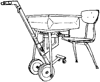
A dolly used to lift a student's desk and some tables of different heights.
This invention enables the operator to move the desk with little effort, and
without disturbing stuff on or in the object. The dolly has an angled
platform which is also adjustable for height, so that when the handle is
tilted
back the platform lifts the object horizontally.
Brief Description Of The Drawings
Figurel is a view of the embodiment lifting a student desk.
Figure 2 is a side view of the invention.
Figure 3 is a view of the handle.
Figure 4 is a view of the vertically elongated supporting frame.
Figure 5 shows an embodiment of the platform, which goes under the
object to be lifted.
Figure 6 is a view of the front platform section.
Figure 7 is a view of the rear support bar.
P.2

CA 02322242 2003-11-18
Detailed Description
The dolly section illustrated in Figure 3 shows an embodiment of the
handle, which contains a pipe (1 ) that goes through a square tubing (2) at
the
top and can be covered with rubber hand grips. Square tubing (2) is cut and
welded to form an elbow extending in a rearward direction and the top end of
(2) can have a plastic cap. The smaller square tubing (3) is welded to the
bottom of (2), and has holes (4) for adjusting the height, with which a quick
pin may be used.
In Figure 4 the vertically elongated square tubing frame has a hole (6) near
the top to align piece (3) from Figure 3 into shaft (5). Shaft (5) has holes
(7)
drilled on one side for adjusting the height. The front lower end support
piece
(8) is made from metal channeling and has a piece of angle iron (9) under it
for support. Metal channeling (10) is welded to (8), it has a piece of flat
iron
(11 ) under it for strength, and has one wheel (12) at each end. The lower
rear support bar is a piece of square tubing (13) welded to (5), and a piece
of pipe (17) through (13) as shown in Figure 7. It also has two support
braces (15) made of flat iron on each side of piece (13). Wheels (16) go on
each side of rod (18), which goes in pipe (17) and through square tubing
(13). The end of (13) may have a plastic cap. A hole (14) on each end of
rod (18) is for holding wheel (16) in place with cotter pins.
Figure 5 shows an embodiment of the platform, which goes under the
object to be lifted. It consists of a piece of square tubing (19), which is a
little
bigger than square tubing (5) shown in Figure 4. Square tubing (19) has a
felt lining in it. On the side of (19) is a piece of cut square tubing (20)
which is
welded. A hole is drilled through (20) and (19) and a spring loaded pin (21)
oes in it. A piece of square tubing (22) is welded to the front bottom of
~19), and piece (23) is welded to (22). Square tubing (24) is cut to the
same angle as (23) and welded to (22). Square tubing (24) has a brace
(25) that is welded to (19). A piece of square tubing (26) is welded on top
of pieces (24) and (23), with one hole (27) through it at the bottom end.
The square tubing is welded such that it is angled forwardly and downwardly.
Square tubing (26) has a felt lining in it. On top of (26) is a piece of
welded
metal channeling (28), with a wheel (29) at each end.
Figure 6 shows an embodiment of the front platform section, which fits into
square tubing (26) in Figure 5, and held in place with a quick pin. Square
tubing (30) is smaller than square tubing (26) in Figure 5, so that it fits
into it.
Square tubing (30) has holes (31) in it to adjust the length. Square tubing
(32) is welded to piece (30), and has a threaded rod (33) at each end.
Threaded rods (33) can have rubber tips.
P.3

Representative Drawing
A single figure which represents the drawing illustrating the invention.
Administrative Status

2024-08-01:As part of the Next Generation Patents (NGP) transition, the Canadian Patents Database (CPD) now contains a more detailed Event History, which replicates the Event Log of our new back-office solution.

Please note that "Inactive:" events refers to events no longer in use in our new back-office solution.

For a clearer understanding of the status of the application/patent presented on this page, the site Disclaimer , as well as the definitions for Patent , Event History , Maintenance Fee  and Payment History  should be consulted.

Event History

Description Date
Time Limit for Reversal Expired 2011-10-12
Inactive: Adhoc Request Documented 2011-07-14
Letter Sent 2010-10-12
Inactive: Office letter 2007-10-16
Inactive: IPC from MCD 2006-03-12
Inactive: S.8 Act correction requested 2004-04-30
Grant by Issuance 2004-04-13
Inactive: Cover page published 2004-04-12
Publish Open to Licence Request 2004-02-04
Pre-grant 2004-02-04
Inactive: Final fee received 2004-02-04
Notice of Allowance is Issued 2004-01-14
Letter Sent 2004-01-14
Notice of Allowance is Issued 2004-01-14
Inactive: Approved for allowance (AFA) 2003-12-22
Amendment Received - Voluntary Amendment 2003-11-18
Inactive: S.30(2) Rules - Examiner requisition 2003-10-29
Amendment Received - Voluntary Amendment 2003-08-05
Inactive: S.30(2) Rules - Examiner requisition 2003-03-20
Amendment Received - Voluntary Amendment 2002-05-09
Inactive: S.30(2) Rules - Examiner requisition 2002-04-22
Application Published (Open to Public Inspection) 2002-04-12
Inactive: Cover page published 2002-04-11
Amendment Received - Voluntary Amendment 2002-03-04
Inactive: S.30(2) Rules - Examiner requisition 2002-02-05
Amendment Received - Voluntary Amendment 2001-12-04
Inactive: S.30(2) Rules - Examiner requisition 2001-08-21
Letter Sent 2001-03-27
All Requirements for Examination Determined Compliant 2001-03-09
Request for Examination Requirements Determined Compliant 2001-03-09
Request for Examination Received 2001-03-09
Inactive: IPC assigned 2000-11-23
Inactive: First IPC assigned 2000-11-23
Filing Requirements Determined Compliant 2000-11-09
Inactive: Filing certificate - No RFE (English) 2000-11-09
Application Received - Regular National 2000-11-08
Small Entity Declaration Determined Compliant 2000-10-12

Abandonment History

There is no abandonment history.

Maintenance Fee

The last payment was received on 2003-07-31

Note : If the full payment has not been received on or before the date indicated, a further fee may be required which may be one of the following

  • the reinstatement fee;
  • the late payment fee; or
  • additional fee to reverse deemed expiry.

Please refer to the CIPO Patent Fees web page to see all current fee amounts.

Fee History

Fee Type Anniversary Year Due Date Paid Date
Application fee - small 2000-10-12
Request for examination - small 2001-03-09
MF (application, 2nd anniv.) - small 02 2002-10-14 2002-08-01
MF (application, 3rd anniv.) - small 03 2003-10-13 2003-07-31
Final fee - small 2004-02-04
MF (patent, 4th anniv.) - small 2004-10-12 2004-09-17
MF (patent, 5th anniv.) - small 2005-10-12 2005-09-02
MF (patent, 6th anniv.) - small 2006-10-12 2006-09-20
MF (patent, 7th anniv.) - small 2007-10-12 2007-09-27
MF (patent, 8th anniv.) - small 2008-10-13 2008-09-29
MF (patent, 9th anniv.) - small 2009-10-13 2009-10-02
Owners on Record

Note: Records showing the ownership history in alphabetical order.

Current Owners on Record
ARTHUR CORRIVEAU
Past Owners on Record
None
Past Owners that do not appear in the "Owners on Record" listing will appear in other documentation within the application.
Documents

To view selected files, please enter reCAPTCHA code :


To view images, click a link in the Document Description column. To download the documents, select one or more checkboxes in the first column and then click the "Download Selected in PDF format (Zip Archive)" or the "Download Selected as Single PDF" button.

List of published and non-published patent-specific documents on the CPD .

If you have any difficulty accessing content, you can call the Client Service Centre at 1-866-997-1936 or send them an e-mail at CIPO Client Service Centre.


Document
Description 
Date
(yyyy-mm-dd) 
Number of pages   Size of Image (KB) 
Representative drawing 2002-03-18 1 11
Description 2003-08-05 2 108
Abstract 2003-08-05 1 17
Claims 2003-08-05 2 106
Description 2003-11-18 2 96
Claims 2002-05-09 1 80
Description 2000-10-12 2 91
Drawings 2000-10-12 3 44
Claims 2001-12-04 1 40
Description 2001-12-04 2 99
Abstract 2001-12-04 1 18
Claims 2002-03-04 1 59
Cover Page 2002-04-09 1 35
Abstract 2001-03-09 1 14
Claims 2001-03-09 1 17
Representative drawing 2004-03-11 1 13
Cover Page 2004-03-11 1 37
Claims 2003-11-18 2 97
Cover Page 2004-05-21 2 95
Claims 2004-05-21 2 91
Filing Certificate (English) 2000-11-09 1 163
Acknowledgement of Request for Examination 2001-03-27 1 178
Notice: Maintenance Fee Reminder 2002-07-15 1 130
Notice: Maintenance Fee Reminder 2003-07-15 1 115
Commissioner's Notice - Application Found Allowable 2004-01-14 1 161
Notice: Maintenance Fee Reminder 2004-07-13 1 119
Notice: Maintenance Fee Reminder 2005-07-13 1 117
Notice: Maintenance Fee Reminder 2006-07-13 1 118
Notice: Maintenance Fee Reminder 2007-07-16 1 121
Notice: Maintenance Fee Reminder 2008-07-15 1 122
Notice: Maintenance Fee Reminder 2009-07-14 1 118
Notice: Maintenance Fee Reminder 2010-07-13 1 122
Maintenance Fee Notice 2010-11-23 1 170
Second Notice: Maintenance Fee Reminder 2011-04-13 1 121
Notice: Maintenance Fee Reminder 2011-07-13 1 121
Correspondence 2000-11-08 1 14
Fees 2003-07-31 1 66
Correspondence 2004-02-04 1 21
Fees 2002-08-01 2 36
Correspondence 2004-04-30 1 18
Fees 2004-09-17 1 66
Fees 2005-09-02 1 82
Fees 2006-09-20 1 20
Correspondence 2007-10-16 2 64
Fees 2007-09-27 1 59
Fees 2008-09-29 1 65
Fees 2009-10-02 1 58