Language selection

Search

Patent 2322265 Summary

Third-party information liability

Some of the information on this Web page has been provided by external sources. The Government of Canada is not responsible for the accuracy, reliability or currency of the information supplied by external sources. Users wishing to rely upon this information should consult directly with the source of the information. Content provided by external sources is not subject to official languages, privacy and accessibility requirements.

Claims and Abstract availability

Any discrepancies in the text and image of the Claims and Abstract are due to differing posting times. Text of the Claims and Abstract are posted:

  • At the time the application is open to public inspection;
  • At the time of issue of the patent (grant).
(12) Patent: (11) CA 2322265
(54) English Title: PLOWSHARE PARTICULARLY FOR SEEDING AND EVENTUAL MANURING IN SOIL ON CONTINUOUS LINE
(54) French Title: SOC DE SEMOIR ET EVENTUELLEMENT D'EPANDEUR, A TRAIT CONTINU
Status: Term Expired - Post Grant Beyond Limit
Bibliographic Data
(51) International Patent Classification (IPC):
  • A1B 35/26 (2006.01)
  • A1B 49/06 (2006.01)
  • A1C 5/06 (2006.01)
(72) Inventors :
  • COLLOVATI, MAURO (Italy)
(73) Owners :
  • MAURO COLLOVATI
(71) Applicants :
  • MAURO COLLOVATI (Italy)
(74) Agent: MBM INTELLECTUAL PROPERTY AGENCY
(74) Associate agent:
(45) Issued: 2006-05-30
(86) PCT Filing Date: 1999-02-19
(87) Open to Public Inspection: 1999-09-02
Examination requested: 2003-07-14
Availability of licence: N/A
Dedicated to the Public: N/A
(25) Language of filing: English

Patent Cooperation Treaty (PCT): Yes
(86) PCT Filing Number: PCT/IT1999/000039
(87) International Publication Number: IT1999000039
(85) National Entry: 2000-08-25

(30) Application Priority Data:
Application No. Country/Territory Date
UD98A000028 (Italy) 1998-02-26

Abstracts

English Abstract


Plowshare particularly for seeding and eventual manuring in soil on continuous
line, of the type involving two equal and symmetrical
opposite convergent wings with an apex having a substantially "V" shaped plan,
characterised in that: said two wings are shaped like
airplane wings having a "substantially V" shaped plan (31); and their ends are
turned upwards (32), in order to allow that: said plowshare
may be pulled penetrating at a certain depth into the soil; cutting the soil
at said depth and making it slide above said wings (31); and said
flaps (32), force said soil to pour back in the obtained furrow covering it;
applying at least one seed distribution device in the free area of
the "V" shaped inside apex being possible.


French Abstract

La présente invention concerne un soc de semoir et éventuellement d'épandeur, à trait continu, du type qui comprend deux versoirs égaux, symétriquement opposés et convergents dont le sommet présente un plan pratiquement en forme de "V", caractérisé en ce que les versoirs ont la forme d'une aile d'avion dont le plan (31) est "pratiquement en forme de V" et leur extrémité (32) est tournée vers le haut, de manière à ce que le soc, lors de sa traction, pénètre dans le sol à une certaine profondeur, coupe le sol et le fasse glisser au-dessus des versoirs (31) et que les ailerons (32) forcent le sol à recouvrir le sillon obtenu, avec la possibilité d'inclure au moins un dispositif de distribution de semences placé à l'intérieur du sommet, dans l'espace libre en forme de "V".

Claims

Note: Claims are shown in the official language in which they were submitted.

Claims
1. A seeding apparatus with plowshares, respectively opening-plowshares
and seeding-plowshare, particularly for the seeding in soil on continuous
line, said seeding-plowshare being of the type involving two equal and
symmetrical opposite convergent wings with an apex having a
substantially "V" shaped plan, wherein:
- the frontal edge of said two wings lies on a substantially horizontal line,
said wings being shaped like airplane wings having a "substantially V"
shape top view (31 ) and;
- their ends are turned upwards to relize a couple of flaps (32),
in order to allow that:
- said plowshare may be pulled penetrating at a certain depth into the soil;
- cutting the soil at said depth and making it slide above said wings (31)
and
- said flaps (32), force said soil to pour back in the obtained furrow
covering it;
characterised in that:
- at least one seed distribution device in the free area of the "V" shaped
inside apex is provided (5) after the rear apex of said seeding-plowshare
(3a):
- the rear edge of said wings (312) is:
- substantially higher than the front edge (311);
- it includes before the front apex of each said plowshare (33) at least an
opening-plowshare for the furrow opening or soil breaking (1),
substantially at a depth greater than the front edge (33-311) of said
seeding-plowshare (3).
2. A Seeding apparatus including an opening-plowshare (1) and a
seeding-plowshare (3) according to the previous claims, characterised in

that said seeding plowshare (3) is connected by means of arms (42) to its
joining central part (34) in a dismountable way, to a support structure (4),
to which also said front opening plowshare (1) is connected in a
dismountable way.

Description

Note: Descriptions are shown in the official language in which they were submitted.


'- ~ CA 02322265 2000-08-25
f , , . .. . . ., .
., ,. -
j
f t
f
t
1 T~IFSCRIP'TION
2 PLOWSHARE PARTICULARLY FOR SEEDING AND EVENTUAL
3 ~VIANURING IN SOIL ON CONTINUOUS LINE
4 Technical Field
The present invention has for object a. plowshare particularly
for seeding
6 and eventual manuring in soil on continuous line.
7 ~~;~round Art (DE-3336217)
8 In prior art different types of plowshares and apparatuses
for seeding and
9 eventual manuring in soil on continuous line are known.
Which substantially consist in having:
11 - means for the opening of furrows in the soil;
12 - means for laying the seed in said furrow;
13 - means for closing the furrow over the seed;
14 - eventual means for spreading the fertiliser along said
furrow.
The present solutions adopt different devices, such as:
16 - a plowshare for opening said furrow followed by the seed
spreader and a
17 tool for closing the furrow;
18 -a spreading tool which also acts as a plowshare by directly
penetrating
19 into the soil.
Closest solutions to the present apparatus are disclosed
in DE-816.771, that
21 suggest the use of plowshare with two equal and symmetrical
opposite
22 convergent wings with an apex having a substantially "V"
shaped plan,
23 said wings being shaped like airplane wings having a "substantially
V"
24 shaped plan (b) and their ends are turned upwards in a helical
shape (b 1 ).
In front of this an upwardly cutter (d) being provided followed
by a
26 swallow tail (a).
27 US-5531277 discloses a bent wing sweep having a modified
shape of the
28 wing in respect to the above solution, not being provided
with a separate
AsJ'wENCE~ ~~EET
IPEr~!EP

,- , CA 02322265 2000-08-25
." .. . , .
' .. .~ . . . ~ -
. . ' '.
.
- ,
1 heading soil cutter. US-5005497 discloses a deep banding
knife with rod
2 attachment.
3 The prior art drawbacks substantially consist of that the
seed taking root
4 is not sure.
In particular the first solution is that which gi res the
best performances,
6 nevertheless even this does not ensure the best taking root
yield.
7 The reason for which all the existing solutions do not ensure
a maximum
8 taking root, substantially derives from that they are not
able to ensure a
9 suitable seed covering in the many operational conditions.
Purpose of the present invention
11 A purpose of the present invention is that of obviating the
12 aforementioned drawbacks and ensuring that the seed falls
on the already
13 tilled and thus suitably covered soft soil.
14 Essence of the invention
The problem is solved as claimed by a seeding apparatus with
plowshares,
16 respectively opening-plowshares and seeding-plowshare, particularly
17 for seeding in soil on continuous line, said seeding-plowshare
being of
18 the type involving two equal and symmetrical opposite convergent
wings
19 with an apex having a substantially "V" shaped plan, wherein:
- the frontal edge of said two wings lies on a substantially
horizontal line,
21 said wings being shaped like airplane wings having a "substantially
V"
22 shaped plan and;
23 - their ends are turned upwards,
24 in order to allow that:
- said plowshare may be pulled penetrating at a certain depth
into the soil;
26 - cutting the soil at said depth and making it slide above
said wings and
27 - said flaps, force said soil to pour back in the obtained
furrow covering
28 it;
A~IIENDED SHEET
IPEAIEP

- CA 02322265 2000-08-25
~ -
., ., ~ ~ '
:i .
'
1 characterised in that:
t one seed distribution device in the free area of the "V"
shaped
l
2 eas
- at
3 inside apex is provided after the rear apex of said seeding-
plowshare;
e of said wings is substantially higher than the front edge;
ec=
h
4 .g
e rear
- t
- it includes before the front apex of each said plowshare
~.t least an
6 opening-plowshare for the furrow opening or soil breaking
( 1 ),
7 substantially at a depth greater than the front edge of said
seeding-
8 plowshare.
9 Advantages of the new solution
~
'
iy
Thus the advantage of sowing the seed in a tilled soil both
over and under
11 the seed with a more certain germination is obtained.
12 Preferred variations
13 Advantageously the front edge of said wings (311) lays on
a substantially
14 horizontal line, so that a soil layer having a suitable thickness
may be
easily removed.
16 As much advantageously the rear edge of said wings is:
17 - substantially higher than the front edge;
18 - substantially horizontal or slightly tilted outwards and
downwards.
19 Thus a better efficacy in soil mixing and seed covering is
obtained.
As much advantageously said flaps tighten backwards tending
to slightly
21 heap the removed soil layer which falls back on the same furrow.
22 Description of at least one form of invention embodiment
23 These and other advantages will result from the following
description of
24 an embodiment preferred solution, with the aid of the enclosed
drawings,
whose execution details are not to be considered as limitative
but are only
26 given as examples.
. 27 Figure 1 is a plan view of the seeding plowshare.
28 Figure 2 is a front view of the same plowshare.
AvJfENDED SHEET
lPEAIEP

- CA 02322265 2000-08-25
. ~- , ___ _.
.. .. '
' . . , ~ ;
~ . . '
' , '
..
1 Fig. 3 is a side view of the same plowshare.
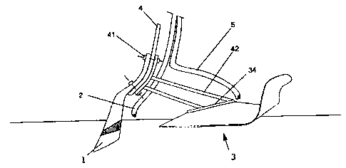
2 Figure 4 is a view of the plowshare assembling in the seeding
system
3 apparatus.
4 According to the figares it may clearly be noticedthe innovatic:n
that
concerns a plowshare particularly for the seedingand eventuil
6 manuring in soil on continuous line, of the two equal and
type involving
7 symmetrical apposite convergent wings with an
apex having a
8 substantially "V" shaped plan, characterised
in that:
9 - said two wings are shaped like airplane wingsa "substantially
having
V" shape top wiew (31 ) and;
11 - their ends are turned upwards to realize a (32),
couple of flaps
12 in order to allow that:
13 - said plowshare may be pulled penetrating at
a certain depth into the soil;
14 - cutting the soil at said depth and making said wings
it slide above (31 )
and
16 - said flaps (32), force said soil to pour backobtained furrow
in the
17 covering it;
1 g - applying at least one seed distribution devicearea of the
in the free "V"
19 shaped inside apex being possible.
The front edge of said wings (311) lays on a horizontal
substantially line
21 The rear edge of said wings (312) is:
22 - substantially higher than the front edge (311);
23 - substantially horizontal or slightly tilted downwards.
outwards and
24 Said flaps tighten backwards tending to slightlythe removed
heap soil
layer which falls back on the same furrow.
26 The seeding apparatus includes the plowshare and within
(3) said
27 plowshare internal rear apex (30) there is a
seed spreader (5).
28 Before the front apex of each said plowshare s a plowshare
(33) there i for
A~JIENDED SHEET
.r,r n !rn
..

CA 02322265 2000-08-25
., . ' _ .
,. ,
_ ' a 5 : . .
the furrow opening or soil breaking (1), substantially at a depth grezter
2 than the front edge of said seeding plowshare
(33-311 ) (3).
3 Before the front apex said plowshare (33) and said openin~t
of after
4 plowshare (1) there
is a seed or fertiliser
spreader (5).
Said seeding plowshare is connected by means of
(3) arms (42) to its
6 joining central part a dismountable way, to a structure
(34) in support (-i ~.
7 to which also said frontopening plowshare (1) is
connected in a
8 dismountable way.
9 Obviously said two plowshares: one, and
the opening or breaking the
seeding one (3) may assembled all in one yet changing
be not the
11 invention essence.
A~ifiEN~Ev SHEET
i~EAIEP

Representative Drawing
A single figure which represents the drawing illustrating the invention.
Administrative Status

2024-08-01:As part of the Next Generation Patents (NGP) transition, the Canadian Patents Database (CPD) now contains a more detailed Event History, which replicates the Event Log of our new back-office solution.

Please note that "Inactive:" events refers to events no longer in use in our new back-office solution.

For a clearer understanding of the status of the application/patent presented on this page, the site Disclaimer , as well as the definitions for Patent , Event History , Maintenance Fee  and Payment History  should be consulted.

Event History

Description Date
Inactive: Expired (new Act pat) 2019-02-19
Inactive: Late MF processed 2014-04-29
Letter Sent 2014-02-19
Small Entity Declaration Determined Compliant 2008-02-25
Small Entity Declaration Request Received 2008-02-25
Grant by Issuance 2006-05-30
Inactive: Cover page published 2006-05-29
Inactive: Final fee received 2006-03-16
Pre-grant 2006-03-16
Inactive: IPC from MCD 2006-03-12
Notice of Allowance is Issued 2005-11-10
4 2005-11-10
Letter Sent 2005-11-10
Inactive: Approved for allowance (AFA) 2005-10-26
Inactive: IPRP received 2004-07-23
Letter Sent 2003-08-15
Request for Examination Received 2003-07-14
Request for Examination Requirements Determined Compliant 2003-07-14
All Requirements for Examination Determined Compliant 2003-07-14
Inactive: Cover page published 2000-11-29
Inactive: First IPC assigned 2000-11-23
Inactive: Notice - National entry - No RFE 2000-11-10
Application Received - PCT 2000-11-09
Application Published (Open to Public Inspection) 1999-09-02

Abandonment History

There is no abandonment history.

Maintenance Fee

The last payment was received on 2006-02-20

Note : If the full payment has not been received on or before the date indicated, a further fee may be required which may be one of the following

  • the reinstatement fee;
  • the late payment fee; or
  • additional fee to reverse deemed expiry.

Patent fees are adjusted on the 1st of January every year. The amounts above are the current amounts if received by December 31 of the current year.
Please refer to the CIPO Patent Fees web page to see all current fee amounts.

Fee History

Fee Type Anniversary Year Due Date Paid Date
Basic national fee - small 2000-08-25
MF (application, 2nd anniv.) - small 02 2001-02-19 2001-02-16
MF (application, 3rd anniv.) - small 03 2002-02-19 2002-02-12
MF (application, 4th anniv.) - small 04 2003-02-19 2003-01-30
Request for examination - small 2003-07-14
MF (application, 5th anniv.) - small 05 2004-02-19 2004-02-17
MF (application, 6th anniv.) - small 06 2005-02-21 2005-02-07
MF (application, 7th anniv.) - small 07 2006-02-20 2006-02-20
Final fee - small 2006-03-16
MF (patent, 8th anniv.) - small 2007-02-19 2007-02-15
MF (patent, 9th anniv.) - standard 2008-02-19 2008-02-19
MF (patent, 10th anniv.) - small 2009-02-19 2009-02-13
MF (patent, 11th anniv.) - small 2010-02-19 2010-02-18
MF (patent, 12th anniv.) - small 2011-02-21 2011-02-15
MF (patent, 13th anniv.) - small 2012-02-20 2012-02-16
MF (patent, 14th anniv.) - small 2013-02-19 2013-02-19
Reversal of deemed expiry 2014-02-19 2014-04-29
MF (patent, 15th anniv.) - small 2014-02-19 2014-04-29
MF (patent, 16th anniv.) - small 2015-02-19 2015-02-17
MF (patent, 17th anniv.) - small 2016-02-19 2016-02-17
MF (patent, 18th anniv.) - small 2017-02-20 2017-02-01
MF (patent, 19th anniv.) - small 2018-02-19 2018-01-30
Owners on Record

Note: Records showing the ownership history in alphabetical order.

Current Owners on Record
MAURO COLLOVATI
Past Owners on Record
None
Past Owners that do not appear in the "Owners on Record" listing will appear in other documentation within the application.
Documents

To view selected files, please enter reCAPTCHA code :


To view images, click a link in the Document Description column (Temporarily unavailable). To download the documents, select one or more checkboxes in the first column and then click the "Download Selected in PDF format (Zip Archive)" or the "Download Selected as Single PDF" button.

List of published and non-published patent-specific documents on the CPD .

If you have any difficulty accessing content, you can call the Client Service Centre at 1-866-997-1936 or send them an e-mail at CIPO Client Service Centre.


Document
Description 
Date
(yyyy-mm-dd) 
Number of pages   Size of Image (KB) 
Representative drawing 2000-11-28 1 5
Cover Page 2000-11-28 1 47
Description 2000-08-24 5 174
Abstract 2000-08-24 1 47
Claims 2000-08-24 2 46
Drawings 2000-08-24 1 21
Representative drawing 2005-11-20 1 7
Cover Page 2006-05-08 1 42
Reminder of maintenance fee due 2000-11-13 1 112
Notice of National Entry 2000-11-09 1 195
Acknowledgement of Request for Examination 2003-08-14 1 173
Commissioner's Notice - Application Found Allowable 2005-11-09 1 161
Maintenance Fee Notice 2014-04-01 1 170
Late Payment Acknowledgement 2014-04-28 1 163
Fees 2012-02-15 1 157
Fees 2013-02-18 1 157
PCT 2000-08-24 15 505
Fees 2003-01-29 1 31
Fees 2001-02-15 1 27
Fees 2002-02-11 1 42
Fees 2004-02-16 1 34
Fees 2005-02-06 1 27
Fees 2006-02-19 1 26
Correspondence 2006-03-15 2 45
Fees 2007-02-14 1 45
Fees 2008-02-18 1 42
Correspondence 2008-02-24 2 78
Fees 2009-02-12 1 51
Fees 2011-02-14 1 202
Fees 2014-04-28 1 26
Fees 2015-02-16 1 26
Fees 2016-02-16 1 26
Fees 2017-01-31 1 26
Maintenance fee payment 2018-01-29 1 26