Note: Descriptions are shown in the official language in which they were submitted.
CA 02322283 2000-08-28
WO 99/45686 PCT/US99/03989
OPTICAL SWITCH FOR HEADSET
Field of the Invention
The invention relates to the field of corded and cordless telephone headsets.
In
particular, the invention relates to a telephone headset having a microphone
boom wherein
the headset is selectively configured to be on, off or muted according to a
rotational
position of the microphone boom.
Background of the Invention
A telephone headset typically includes at least one speaker and a microphone.
Certain headsets include a headband wherein the speaker is attached to the
headband such
that when the headband is placed upon the user's head, the speaker is disposed
over one of
the user's ears. If a second speaker is provided, it is attached to the
headband such that the
second speaker is disposed over the user's other ear. The microphone is
typically
positioned near or in front of the user' s mouth at a first end of a
microphone boom, the
second end of the microphone boom being attached to the headband. Other
headsets are
secured to the user's head by means other than a headband, though such
headsets typically
include a microphone boom for positioning the microphone near the user's
mouth.
Telephone headsets can be corded or cordless.
It can be desirable for the user to control an operative condition of the
headset.
U.S. Patent No. 4,484,029, and entitled, "Cordless Telephone Switch And Line
Selector,"
discloses a cordless headset having a mouthpiece arm that is pivotable with
respect to the
headband. The mouthpiece arm is provided with a pivot means at an end opposite
the
mouthpiece such that rotation of the mouthpiece arm upward locates the
mouthpiece, and
microphone located therein, superiorly to the user's head and simultaneously
disconnects
power to the radio portion of the headset. This is accomplished by ganging the
pivot
means to a wiper-containing rotary switch. Lowering the mouthpiece arm such
that the
microphone is brought in line with the user's mouth rotates the switch wiper
away from the
"off' position and toward an "on" position, thus, connecting the microphone
and powering
the radio. Additional "on" positions are provided, each for a separate radio
transmission
channel.
The wiper and contacts of the aforementioned device may become misaligned,
-1-
CA 02322283 2000-08-28
WO 99/45686 PCT/US99/03989
contaminated or worn, thus, reducing the reliability of the device.
A product, the HelloSet CordlessTM disclosed in Hello Direct, Inc.'s "Catalog
of
Telephone Productivity Tools," Spring 1994, discloses a headset having a
single speaker
and a rotatable microphone boom. Mechanical switches within the headset are
responsive
to the position of the microphone boom; the boom is positioned up for storage
(off). down
for use (on) and in the middle for mute.
The mechanical switches of the aforementioned product may also become
misaligned or worn, thus, reducing the reliability of the device. Further, the
mechanical
switches tend to be relatively large in comparison to electrical components
included in the
aforementioned product. Therefore, what is needed is a technique for
controlling an
operative condition of a headset that does not suffer from the aforementioned
drawbacks.
Summary of the Invention
The invention includes an optical switch for controlling an operative
condition of a
headset. The headset includes a microphone boom that is rotatable with respect
to a
housing for the headset. A rotator element located within the housing is
coupled to the
microphone boom such that the rotator element rotates with respect the housing
along with
the microphone boom. The rotator element has a substantially planar surface
including a
circular portion and a tab extending from the circular portion. The rotator
element rotates
about an axis that is substantially perpendicular to its surface and
approximately at the
center of the circular portion. Selected portions of the surface of the
rotator element are
conditioned to be more reflective than the remaining portions. Particularly,
the tab and a
semi-circle of approximately one-half of the circular portion, as divided by a
diameter
which approximately bisects the tab, is conditioned to be more reflective than
the
remaining portions of the rotator element.
A pair of optical transceivers are fixed relative to the housing and
positioned at
predetermined distances from the rotational axis of the rotator element such
that a first of
the optical transceivers indicates whether or not the tab is positioned
substantially within a
field of view of the first optical transceiver according to a rotational
position of the rotator
element, and a second of the optical transceivers indicates whether or not the
semi-circle is
positioned substantially within a field of view of the second optical
transmitter according to
the rotational position of the rotator element.
-2-
CA 02322283 2004-12-08
76280-16
When the microphone boom is positioned
approximately straight upward with respect to a user's head
as viewed from the side (e.g. approximately 12 noon), the
first optical transceiver is substantially covered by the
tab and the second optical transceiver is substantially
covered by the semi-circle. In this position, the headset
is in an "off" or "standby" mode. When the microphone boom
is positioned approximately level with the ground as viewed
from the side (e.g. between approximately 1 and 3 o'clock or
between 9 and 11 o'clock), the first optical transceiver is
not substantially covered by the tab or the semi-circle,
while the second optical transceiver is substantially
covered by the semi-circle. In this position, the headset
is in an "mute" mode. When the microphone boom is pointing
downward as viewed from the side (e. g. between approximately
4 and 5 o'clock or between 7 and 8 o'clock), neither of the
two optical transceivers is covered by the tab or the semi-
circle. In this position, the headset is in a "talk" mode.
In accordance with one embodiment of the present
invention, a headset having an optical switch for
controlling an operative condition of the headset is
disclosed. The headset comprises: means for securing the
headset to a user; a microphone boom coupled to the means
for securing wherein the microphone boom is rotatable with
respect to the means for securing; a rotator element coupled
to the microphone boom wherein the rotator element rotates
with respect to the means for securing along with the
microphone boom, portions of the rotator element having
dissimilar optical properties; and an optical receiver
having a fixed first position relative to the means for
securing and having a first field of view, the optical
receiver for forming a first binary representation of the
3
CA 02322283 2004-12-08
76280-16
optical properties of the portion of the rotator element
within the first field of view. The headset can also
include a second optical receiver in a fixed position
relative to the means for securing and having a second field
of view, the second optical receiver for forming a second
binary representation of the optical properties of the
portion of the rotator element within the second field of
view wherein the first and second binary representations
determine the operative condition of the headset.
In accordance with an alternative embodiment of
the present invention, a headset having an optical switch
for controlling an operative condition of the headset is
disclosed. The headset comprises means for securing the
headset to a user; a microphone boom coupled to the means
for securing wherein the microphone boom is rotatable with
respect to the means for securing; a rotator element coupled
to the microphone boom wherein the rotator element rotates
with respect to the means for securing along with the
microphone boom, the rotator element having a first
reflective portion; and a first optical transceiver having a
fixed first position relative to the means for securing and
having a first field of view, the first optical transceiver
for sensing whether or not the first reflective portion is
substantially within the first field of view.
In accordance with another embodiment of the
present invention, a headset having an optical switch for
controlling an operative condition of the headset is
disclosed. The headset comprises means for securing the
headset to a user; a microphone boom coupled to the means
for securing wherein the microphone boom is rotatable with
respect to the means for securing; a rotator element coupled
3a
CA 02322283 2004-12-08
76280-16
to the microphone boom wherein the rotator element rotates
about an axis with respect to the means for securing along
with the microphone boom, the rotator element having at
least one optically opaque portion; and a first optical path
positioned between each element of a first optical
emitter/receiver pair wherein the first optical path has a
first fixed position relative to the means for securing
wherein the first optical path is selectively blocked by the
optically opaque portion according to a rotational position
of the rotator element.
In accordance with another embodiment of the
present invention, a headset having an optical switch for
controlling an operative condition of the headset is
disclosed. The headset comprises means for securing the
headset to a user; a microphone boom coupled to the means
for securing wherein the microphone boom is rotatable with
respect to the means for securing; a rotator element coupled
to the microphone boom wherein the rotator element rotates
with respect to the means for securing along with the
microphone boom, the rotator element having a substantially
planar surface wherein selected portions of the surface are
conditioned to be more reflective than remaining portions
and wherein the rotator element rotates about an axis that
is substantially perpendicular to its surface; and a first
optical transceiver having a fixed first position relative
to the means for securing and having a first field of view,
the first optical transceiver for sensing whether or not the
selected portions of the surface conditioned to be more
reflective are substantially within the first field of view.
The means for securing the headset to the user is preferably
a headband. The surface of the rotator element can include
a circular portion having its center located at the axis.
3b
CA 02322283 2004-12-08
76280-16
The headset can further comprise a second optical
transceiver having a fixed second position relative to the
means for securing and having a second field of view, the
second optical transceiver for sensing whether or not the
selected portions of the surface conditioned to be more
reflective are substantially within the second field of
view. The surface of the rotator element can include a tab
extending from the circular portion.
The headset can further comprise a pressing member
for increasing frictional resistance against rotation of the
microphone boom by pressing against the circular portion and
for constraining rotation of the microphone boom by pressing
against the circular portion and for constraining rotation
by contacting the tab. The tab and a semi-circle of
approximately one-half of the circular portion, as divided
by a diameter which approximately bisects the tab, can be
conditioned to be more reflective than the remaining
portions of the rotator element. The first optical
transceiver can have a first radial distance from the axis
and wherein the second optical transceiver has a second
radial distance from the axis. The second radial distance
is preferably greater than the first radial distance. The
first optical transceiver and the second optical transceiver
can be space apart from each other by a predetermined number
of degrees with respect to the axis. The predetermined
number of degrees can be approximately 90 degrees.
Preferably, the headset is controlled to be in a
"standby" condition, a "mute" condition and a "talk"
condition according to the rotational position of the
rotator element. In the "standby" condition, the reflective
portions of the rotator element can be substantially within
3c
CA 02322283 2004-12-08
76280-16
the field of view of the first optical transceiver and the
reflective portions of the rotator element can be
substantially within the field of view of the second optical
transceiver. In the "mute" condition, the reflective
portions of the rotator element can be substantially outside
the field of view of the first optical transceiver and the
reflective portions of the rotator element can be
substantially within the field of view of the second optical
transceiver. In the "talk" condition, the reflective
portions of the rotator element are substantially outside
the field of view of the first optical transceiver and the
reflective portions of the rotator element are substantially
outside the field of view of the second optical transceiver.
Preferably, rotation of the microphone boom from
the "standby" condition in either a clockwise or
counterclockwise direction results in a transition to the
"mute" condition.
Preferably, rotation of the microphone boom from
the "mute" condition results in a transition to the "talk"
condition.
Preferably, a transition to the "talk" condition
places a telephone base unit off-hook by the headset
transmitting a preselected signal to the base unit.
The optical transceivers are less susceptible to
wear, contamination and misalignment and occupies less space
than prior mechanical switch devices.
3d
CA 02322283 2004-12-08
76280-16
Brief Description of the Drawings
Fig. 1 illustrates a perspective view of a headset
according to the present invention having a rotatable
microphone boom.
Fig. 2 Illustrates a side view of various
rotational positions for the microphone boom according to
the present invention.
Fig. 3 illustrates a sectional view of the headset
according to the present invention.
Fig. 4 illustrates a bottom view of the reflective
rotator element according to the present invention.
Fig. 5A-E illustrate a top views of the reflective
rotator element according the present invention in each of
several different rotational positions.
Fig. 6 illustrates perspective view of an
alternate embodiment of the rotator element according to the
present invention which does not require reflective
portions.
Fig. 7 illustrates perspective view of an
alternate embodiment of the headset according to the present
invention having a rotatable microphone boom and which does
not require a headband.
3e
CA 02322283 2000-08-28
WO 99/45686 PCT/US99/03989
Detailed Description of the Preferred Embodiment
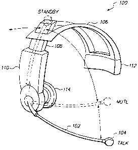
Fig. 1 illustrates a perspective view of a headset 100 according to the
present
invention having a rotatable microphone boom 102. The microphone boom 102
includes a
microphone 104. The headset 100 also includes an arcuate headband 106, an
adjustment
mechanism 108 for selectively sizing the headband 106, a housing 110 which
contains
circuitry associated with the headset 100 and mechanical apparatus for
rotational attachment
of the microphone boom 102, a battery 112 for powering the circuitry contained
in the
housing 110 and a speaker 114.
Preferably, the headset 100 is a cordless telephone headset. In which case, a
wireless communication link is established between the headset 100 and a base
unit (not
shown). Accordingly, the housing 110 preferably includes a radio transmitter
for
transmitting signals picked up by the microphone 104 to the base unit and a
radio receiver
for receiving signals from the base unit and applying them to the speaker 114.
The microphone boom 102 is rotatable with respect to the housing 110 and the
headband 106 for controlling an operative condition of the headset 100. When
the
microphone boom 102 is positioned approximately straight upward with respect
to a user's
head (e.g. approximately between 11 o'clock and 1 o'clock), the headset 100 is
preferably
in an "off' or "standby" mode. In this mode, the microphone 104 and speaker
114 are
inoperative for communicating voice signals, however, the base unit preferably
can notify
the user of an incoming call by transmitting a preselected ring signal to the
headset 100.
When the microphone boom 102 is positioned at greater angle with respect to
the
headband 106 (e.g. between approximately 1 and 3 o'clock), the headset is
preferably in a
"mute" mode. In the mute mode, the user can receive and listen to voice
signals from the
base unit, though the headset transmitter and/or microphone 104 are
conditioned to be
inoperative for communication.
When the microphone boom is pointing downward as viewed from the side (e.g.
between approximately 4 and 5 o'clock), the headset is preferably in a "talk"
mode. In this
mode, both the microphone 104 and the speaker 114 are operative for carrying
on a two-
way conversation. In addition, upon transitioning from the "standby" position
to the "talk"
position, the headset 100 preferably sends a preselected signal to the base
unit which
instructs the base unit to go off hook. In this manner, an incoming telephone
call can be
answered remotely by the user. Conversely, a transition to the "standby" mode
signals the
-4-
CA 02322283 2004-12-08
~: ~so-is
base emit to return to an on-hook condition for reasotely oermiflatiag a
incocaiag or
owgoing tdcphone adl. Such an autosnstic reatote on-LookMff Gook systeta is
~sclosed
in commonly owned U. S. Patent No. 6, 081.. 596, and entitled
AUTOMATIC ANSWERxNG $ICtCC-ITP DEVICE .
Fig. 2 :t side view of variona totabonal pe~oas for the ml~pho~
boom 102 whore the sans of is peapandiwG~r to Wye pie at point A. ~
Preferably, a
1'~ Of pD~tWaf 00~0~a tD ~ 0m0dd ~'r~ ~m~C,~ 0l
"tall' ). Also, tLe range of rotational positions of the microphone boom 102
for crab
rIO. mbodo sre boatod sy~oOetrica,Uy shoat 0 dog~ea. This allawa the hasdaat
100 to
be positioned on the user's !read such thd the apaloet 114 covrsa etiba tba
right ass or the
lei .ear without requiring tn~odi$cation to the l~dset 100.
?he streigbct up poaiti~ of the micropho~ booam 102 as Olu~ra<ed aligned with
the beadbaod iv FiO. 1 coexespoods to o in pig. 2 7"he "~dby' m,odc ~udex
1 s tie o ae~ree aaa fly a~a snm a~wa~atr ,~s d~~a co
ama~ly +3s ae~. ~rbe "mme~ mere ~ ap~y *3s to
approximately +100 d~ees.~ 'Ibe "nmoe' mode also extends from approovmatety -
35
dews to uPpro~ximatdy -100 degrees. Z1e "talY' mode eaaaods from appw~tima~e~r
+100
deg:~eess to ~prox~amc~y +135 dews. T6e "talk' a~odo also ex~ds from
appcoximaody
20 --100 degred to -133 d~rees. Preferab~r, bra micto~phaae boom is
meehanieal~r
oa~raisea $nm rod beyoa~d approxinu~te>y +13s dagrees and -135 degrees as win
be
explained bekmr
Fig. 3 ~ a 1 view of a pcutio~a of the Irmdmt hod I10 isxludiag
t meclumical 200 for rotaCi~al sttaahment of the one boom 102. The
ZS aectio~n bisecxa the ha~rsing 110 along its length sad thnoagb the mtanamal
nuns A. '!!~e
taicropir~e boom 102 is caopl~cd to a shag tnamubae 202: The houaiug 110
itrdndea a
ciroolmr opening boaaded by a lip 204 for accept~g the shelf member 20Q. The
shaft
mamba 202 indudea a r~itiam cir~ler f~nge Z06 and catoufat t~ 200 for ~ini~g
the
lip 24.4 tlu~ebawee~t.
30 Fig. 4 Ohrs6atea a bosom view of a mtamr dement 210 (Fig. 3) a~ooosdmg w
the
prvsatt inv~on. The rat~or element ZIO includes s substaadally circular
portion 210A
and a sector-ehapod tab 218H acoendidg flrom t4e cie~r portion 210A. The tab
21~OB and
CA 02322283 2000-08-28
WO 99/45686 PCT/US99/03989
a semi-circular sector of the circular portion 210A which includes
approximately one-half
of the circular portion 210A. as divided by a diameter which approximately
bisects the tab
210B, are conditioned to be more optically reflective than the remaining
portions of the
rotator element 210. This conditioning is preferably accomplished by applying
an optically
S reflective coating 212 to these selected portions of the rotator element
210. The optically
reflective coating 212 can be formed for example of aluminum or solder.
Preferably, the
rotator element 210 is formed of fiberglass and resin, similarly to a printed
circuit board.
Three apertures are provided in the rotator element 210 for facilitating
attachment of the
rotator element 210 to the shaft member 202 (Fig. 3).
Referring to Fig. 3, the rotator element 210 is coupled to the shaft member
202
such that the bottom surface of the rotator element 210 faces the shaft member
202 and
such that the rotator element 210 rotates concurrently with the microphone
boom 102 and
shaft member 202 about the axis A. A fourth aperture 216 (Fig. 4) is provided
in the
rotator element 210 for passage of a pair of microphone wires 218 from the
microphone
104 (Fig. 1 ).
A resilient pressing member 220 is coupled to the housing 110 and presses
against
the circular portion 210A of the rotator element 210 for increasing frictional
resistance
against rotation of the rotator element 210, shaft member 202 and microphone
boom 102.
This frictional resistance maintains the microphone boom 102 in a desired
position during
use of the headset 100. In addition, the pressing member 220 prevents the
microphone
boom 102 from rotating beyond +135 degrees or beyond -135 degrees by
contacting the tab
210B (as illustrated in Figs. SD and SE). Tension of the pressing member 220
against the
rotator element 210 is preferably maintained by attachment of the pressing
member 220 to
the housing 110 by a screw 222 and by engaging a circular groove 224 in the
shaft element
202.
A printed circuit board (PCB) 226 provides circuitry for the headset 100. The
circuitry includes the radio transmitter and receiver discussed above, in
addition to a circuit
for interfacing the microphone 104 (Fig. 1 ) to the radio transmitter and for
interfacing the
receiver to the speaker 114 (Fig. 1 ). In addition, a pair of optical
transceivers 228, 230,
each having an optical transmitter and an optical receiver, and associated
circuitry are
mounted to the PCB 226 near the rotator element 210 for controlling an
operational
condition of the headset 100 ("standby," "mute," "talk").
-6-
CA 02322283 2000-08-28
WO 99/45686 PCT/US99/03989
The circuitry of the PCB 226 provides a binary indication of whether or not
the
reflective coating 212 on the bottom of the rotator element 210 is
substantially within the
field of view of each of the optical transceivers 228, 230. Thus, the amount
of light
received by the optical transceivers 228, 230 is converted to signals that are
compared to
predetermined thresholds. The predetermined thresholds are preferably
independently
adjustable to fine tune the device and to accommodate manufacturing
variations. The
optical transceivers 228, 230 preferably utilize infrared light. To shield
extraneous light
from interfering with the optical transceivers 228, 230, the housing 110
preferably encloses
the rotator element 210 and optical transceivers 228, 230, as illustrated in
Fig. 1.
Figs. SA-E illustrate a top views of the rotator element 210 according the
present
invention in each of several different rotational positions with respect to
the optical
transceivers 228, 230. For reference, the pressing member 220 and rotational
axis A are
also illustrated in Figs. SA-E. Note that because the optical transceiver 228
is located
farther from the rotational axis A of the rotator element 210 than the optical
transceiver
230, the reflective coating 212 on the bottom surface of the circular portion
210A of the
rotator element 210 is preferably never within the field of view of the
optical transceiver
228 for all possible rotational positions of the rotator element 210. Note
also, that the
optical transceivers 228 and 230 are spaced apart from each other by
approximately 90
degrees with respect to the rotational axis A. While this angular spacing is
preferred, other
angular spacings can also be used to achieve the benefits of the present
invention by
following the teachings herein.
Fig. SA illustrates the rotator element 210 in a straight-up position. This
position
corresponds to the range of angles identified as standby and as shown in Fig.
2. In this
position, the reflective coating 212 on the bottom surface of the tab 210B
optical
transceiver 228 is located substantially within the field of view of the
optical transceiver
228 and the reflective coating 212 on the bottom surface of the circular
portion 210A of
the rotator element 210 is located substantially within the field of view of
the optical
transceiver 230. In this position, the headset is in the "standby" mode. Note
that the
rotator element 210 can be rotated in either direction (clockwise or
counterclockwise) by a
predetermined amount while maintaining a sufficient quantity of the reflective
coating 212
within the field of view of the optical transmitters 228, 230 to maintain the
headset 100 in
the "standby" mode. As illustrated in Fig. 2, the "standby" mode preferably
includes a
CA 02322283 2000-08-28
WO 99/45686 PCT/US99/03989
range extending from -35 degrees to +35 degrees. The precise limits of this
range,
however, are not critical in that variations due to manufacturing tolerances
or aging of the
headset 100 will not adversely affect its operation.
When the microphone boom 102 is rotated such that the reflective coating 212
on
the bottom of the tab 210B is substantially outside of the field of view of
the optical
transceiver 228, while the reflective coating 212 on the bottom of the
circular portion 210A
of the rotator element 210 remains substantially within the field of view of
the optical
transceiver 230 regardless of the direction of rotation. When this occurs the
headset enters
the "mute" mode. This configuration is illustrated in Figs. SB and SC. Note
that similar to
the "standby" mode, the "mute" mode corresponds to a range of rotational
positions of the
microphone boom 102. In addition, because there are two positions of the
rotator element
210 which correspond to the "mute" mode, as illustrated in Figs. SB and SC,
there are two
ranges of positions, as illustrated in Fig. 2, for the microphone boom 102
which correspond
to the "mute" mode. Again, the precise limits of this range are not critical
for operation of
the headset 100.
When the microphone boom 102 is rotated even further in either direction of
rotation such that the reflective coating 212 on the bottom of the rotator
element 210 is
substantially outside of the field of view of the optical transceiver 228 and
substantially
outside the field of view of the optical transceiver 230, headset 100 enters
the "talk" mode.
This configuration is illustrated in Figs. SD and SE. Note that similar to the
"standby" and
"mute" modes, the "talk" mode corresponds to a range of rotational positions
of the
microphone boom 102. In addition, similarly to the "mute" mode, because there
are two
positions of the rotator element 210 which correspond to the "talk" mode, as
illustrated in
Figs. SD and SE, there are two ranges of positions, as illustrated in Fig. 2,
for the
microphone boom 102 which correspond to the "talk" mode. The ranges for the
"talk"
mode, however, are preferably mechanically constrained by the pressing member
222
limiting the rotation of the rotational element 210 when the tab 210B contacts
the pressing
member 222, as illustrated in Figs. 5 D and SE.
Fig. 6 illustrates perspective view of an alternate embodiment of the rotator
element
according to the present invention which does not require reflective portions.
Rather, the
rotator element 300 includes sectors having dissimilar radial dimensions about
its axis of
rotation B and which are formed of a material which is substantially opaque.
The rotator
_g_
CA 02322283 2004-12-08
76280-16
element 300 illustrated in is utilized in conjunction with
emitter/receiver pairs 302A-B, 304A-B. Because the elements
of each emitter/receiver pair 302A-B, 304B are positioned on
opposite sides of the rotator element 300 and because the
rotator element 300 includes optically opaque sectors having
dissimilar radial dimensions, the rotator element 300
substantially blocks a light path between both, only one, or
neither of the emitter/receiver pairs 302A-B, 304A-B
depending upon its rotational position with respect to the
emitter/receiver pairs 302A-B, 304A-B.
The element 302A can be an emitter, in which case,
the element 302B is a receiver, or vice-versa. Similarly,
the element 304A can be an emitter, in which case, the
element 304B is a receiver, or vice-versa. Thus, when the
rotator element 300 is positioned to substantially block the
light path between the elements 302A and 302B and also
substantially blocks the light path between the elements
304A and 304B, this corresponds to the "standby" mode. When
the rotator element 300 is positioned to substantially block
the light path between the elements 304A and 304B, but does
not block the light path between the elements 302A and 302B,
this corresponds to the "mute" mode. Further, when the
rotator element 300 is positioned to avoid blocking the
light path between the elements 302A and 302B and also
avoids blocking the light path between the elements 304A and
304B, this corresponds to the "talk" mode.
Fig. 7 illustrates perspective view of an
alternate embodiment of the headset 400 according to the
present invention having a housing 402 coupled to a
rotatable microphone boom 404. The headset 400 illustrated
in Fig. 7 differs from the headset 100 illustrated in Fig. 1
9
76280-16
CA 02322283 2004-12-08
primarily in that the headset 400 does not require a
headband. Rather, the headset 400 is supported on the head
of a user by insertion of an earphone member 406 into the
user's outer ear. It will be apparent that other, or
additional, means can be provided for supporting the headset
400 on the user. For example an adjustably expandable
member can be inserted into the user's ear, such as is
disclosed in U.S. Patent No. 5,953,435, entitled, "Intra-
Concha Stabilizer With Length Adjustable Chonchal Wall
Hook", or a clamping member can be provided for clamping to
outer portions of the user's ear.
The headset 400 illustrated in Fig. 7 also differs
from the headset 100 illustrated in Fig. 1 in that the
heaset 400 includes a cord 408 for coupling the headset 400
to a telephone base unit (not shown). It will be apparent
that the headset 400 (Fig.7) can be
9a
CA 02322283 2000:-08-28
IvCCV. 1''()~yh'A ..Mll~_\~C:FIW\y)I ~ _ . _~:'E'. =.1' ~) . (I . U..i :
E:uU$a;311] 7f1~ ~ n c r
PAT'~NT
HELLO-05401
unplemented as a cordless headset and that the headset (Fig. 1 ) can be
implemented a~ a
corded headset.
The ho~aing 402 can include a rotator element, such as the rotator element 2I
G
illustrated in Figs. 3-S or the rotator element 300 illustrated in Fig. 6,
with appropriatf
circuits and rncchanical elements for controlling an operative condition of
the headset X00
according to a rotational position of the microphone boom 404 relative the
housing 40i.
More particularly, the headset 400 can be selectively placed in the "standby,"
"mute" and
"talk" modes by rotation of the microphone boom 404 relative the housing 402.
It wi;l be
apparent that the rotational positions illus~ted in Fig. 2 can be utilized for
the headset
400.
Aitemateh~, different rotational positions, or ranges of positions, of the
micropl~onc
boom 404 relative the housing 402 or of the microphone boom 102 relative the
housir~.g
110 can be utilized depending upon the circumstances.
The present invention has bean described in terms of specific embodimenu
incorporating details to facilitate the understanding of the principles of
construction and
operation of the invention. Such reference herein to specific embodiments and
details
thereof is not intended to limit the scope of the claims appended hereto. It
will be
apparent to those skilled in the art that modifications may be made in the
embodimem
chosen for illu~rtration without departing from the scope of the invention.
Specifically, it
will be apparent to one of ordinary skill in the act that th;, method of the
present invention
could be implemented in several different ways and the apparatus disclosed
above is only
illt~strxtive of the preferred embodiment of the present invention and is in
no way a
limitation. Far example, the axis of rotation for the rotator element need not
intersect the
area of the rotator element.
substitute sheet
- 10
AMENDED SHEET