Language selection

Search

Patent 2322407 Summary

Third-party information liability

Some of the information on this Web page has been provided by external sources. The Government of Canada is not responsible for the accuracy, reliability or currency of the information supplied by external sources. Users wishing to rely upon this information should consult directly with the source of the information. Content provided by external sources is not subject to official languages, privacy and accessibility requirements.

Claims and Abstract availability

Any discrepancies in the text and image of the Claims and Abstract are due to differing posting times. Text of the Claims and Abstract are posted:

  • At the time the application is open to public inspection;
  • At the time of issue of the patent (grant).
(12) Patent: (11) CA 2322407
(54) English Title: CURVED-BEAM PUMPING UNIT
(54) French Title: UNITE DE POMPAGE A BALANCIER COURBE
Status: Term Expired - Post Grant Beyond Limit
Bibliographic Data
(51) International Patent Classification (IPC):
  • F04B 47/02 (2006.01)
  • E21B 43/12 (2006.01)
(72) Inventors :
  • GUO, DONG (China)
  • BAI, XUEMING (China)
  • ZHANG, ZIZHONG (China)
  • SU, JINYANG (China)
(73) Owners :
  • CHINA NATIONAL PETROLEUM CORPORATION
(71) Applicants :
  • CHINA NATIONAL PETROLEUM CORPORATION (China)
(74) Agent: RICHES, MCKENZIE & HERBERT LLP
(74) Associate agent:
(45) Issued: 2005-02-01
(22) Filed Date: 2000-10-05
(41) Open to Public Inspection: 2001-04-13
Examination requested: 2001-12-14
Availability of licence: N/A
Dedicated to the Public: N/A
(25) Language of filing: English

Patent Cooperation Treaty (PCT): No

(30) Application Priority Data:
Application No. Country/Territory Date
99248371.9 (China) 1999-10-13

Abstracts

English Abstract

A curved-beam pumping unit is provided, in which a support and a speed reducer are both affixed to a base, a beam seat is mounted on an upper end of the support, and a coupler assembly is connected at one end to a crossbeam fixed on a walking beam and connected at the other end to a crank which connecting the speed reducer with a crank balance, characterized in that the rear end of the walking beam is formed as curved shape and having a balance weight mounted on its tail part.


French Abstract

Unité de pompage à balancier incurvé, comprenant un support et un réducteur de vitesse fixés à une base, une assise de poutre est montée à l'une des extrémités supérieures du support, et un système de coupleur est relié à une extrémité de la traverse et fixé au balancier, et relié à une manivelle à l'autre extrémité, reliant le réducteur de vitesse au poids d'équilibrage de la manivelle, caractérisé par le fait que l'extrémité arrière du balancier est incurvée et que son contrepoids se trouve au niveau de la queue.

Claims

Note: Claims are shown in the official language in which they were submitted.

Claims
1. A curved-beam pumping unit, in which a support and a speed reducer
are both affixed to a base, a beam seat is mounted on an upper end of the
support, and a coupler assembly is connected at one end to a crossbeam fixed
on
a walking beam and connected at the other end to a crank which connecting the
speed reducer with a crank balance, characterized in that the rear end of the
walking beam is formed as curved shape and having a balance weight mounted
on its tail part.
2. The curved-beam pumping unit as claimed in claim 1, wherein the
number and position of the balance weight mounted on the rear end of the
walking beam are adjustable.
3. The curved-beam pumping unit as claimed in claim 1, wherein the beam
seat is installed diametrically at the fulcrums on an upper, lower or middle
part of the walking beam.
4. The curved-beam pumping unit as claimed in claim 1, wherein the
walking beam is formed as staggered or zigzag shape.
5

Description

Note: Descriptions are shown in the official language in which they were submitted.


CA 02322407 2000-10-OS
Curved-beam Pumping Unit
The present invention relates to a pumping apparatus for oil production.
This apparatus belongs to a kind of curved-beam pumping unit.
At present, for non-flowing oil wells, it is generally exploited with
mechanical pumping units, such as the most widely used curved-beam pumping
units. In a curved-beam pumping unit, a walking beam is pivotally supported
on a support via a beam seat, a horsehead is installed on a front end of the
walking beam and connected with a pumping rod though a cable suspension, a
rear end of walking beam is pivoted on a crank and coupler mechanism by a
crossbeam, and a motor drives the crank and coupler mechanism via a speed
reducer. The walking beam is driven by the crank and coupler mechanisms
through the crossbeam, to swings reciprocally in a vertical plane. Therefore,
the
horsehead and the cable suspension can drive the pumping rod moving up and
down reciprocally, to pumping oil. The walking beam type pumping unit has the
advantages of working reliably, being sturdy and durable, easy to maintain,
and
working in open fields perennially without inspected especially. However, in
the
past more than 100 years, walking beam type pumping units have been affected
by the four-bar linkage, so that the load acting on the crank which is
resulted
from the load at suspension point of pumping unit does not vary sinuously.
Furthermore, being affected by additional loads during operating, including
the
inertial load at suspension point, the loading torque curve would deform.
Therefore, the crank balancing torque, which varies sinuously, could not
balance
with the load torque. In addition, the net output torque of the crank in one
turn
would arises a relatively high peak value and a relatively low valley
(negative)
value, so that the energy consumption of the pumping unit is increased and the
efficiency of the pumping unit is decreased. Meanwhile, the lifetime of the
speed reducer would be sacrificed from the negative torque.
1

CA 02322407 2000-10-OS
With the development of oil wells, the liquid level of oil well lowers
gradually, the number of flowing wells decreases progressively, and more and
more pumping units are put into use. As a result, the problems about long
stroking and deep pumping, the increasing of efficiency of pumping unit, and
the lowering of energy consumption, etc., appear to be more significant.
It is an object of the present invention to provide a curved-beam pumping
unit which can avoid the disadvantages in the prior art, and to provide an
energy-economized pumping unit with long stroke, low energy consumption and
high efficiency, and being sturdy and durable and easy to operate.
The above object has been obtained by a curved-beam pumping unit, in
which a support and a speed reducer are both affixed to a base, a beam seat is
mounted on an upper end of the support, and a coupler assembly is connected at
one end to a crossbeam fixed on a walking beam and connected at the other end
to a crank which connecting the speed reducer with a crank balance,
characterized in that the rear end of the walking beam is formed as curved
shape
and having a balance weight mounted on its tail part.
The number and position of the balance weight mounted on the rear end of
the walking beam are adjustable.
The beam seat may be installed diametrically at the fulcrums on the upper,
lower or middle part of the walking beam, and the walking beam may be formed
as staggered or zigzag shape.
The present invention has the advantages as follows:
2

CA 02322407 2000-10-OS
1. The balancing effect of the pumping unit is improved, and the peak and
valley values of net output torque of the crank are decreased.
2. The stress of four-bar linkage is reduced, the swing angle increased, a
long stroke can be obtained, the reliability of the components is raised, and
the
features of normal beam pumping unit, such as structural simplicity,
reliability
and durability, can be possessed.
3. The energy consumption of the pumping unit is decreased, so as to
increasing the overall efficiency.
The present invention is to be explained with exemplary embodiments and
in connection with the drawings, in which:
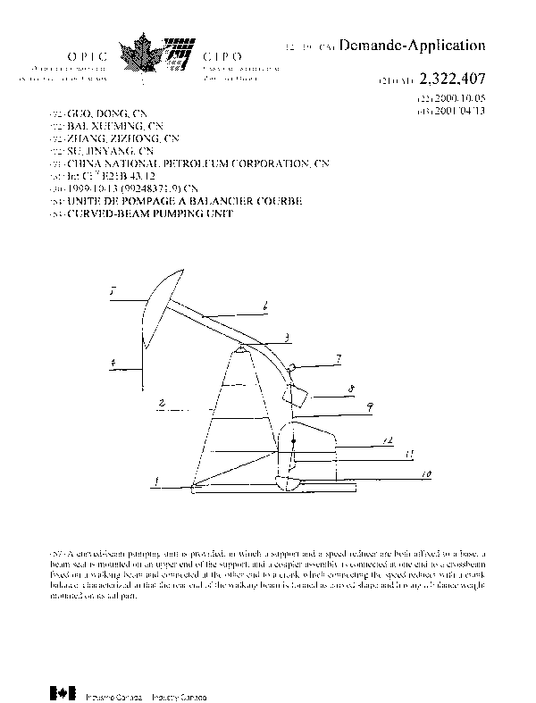
Fig. 1 is a schematic drawing of the structure of a curved-beam pumping
unit.
Fig. 2 is a schematic drawing of a walking beam and a beam seat of the
curved-beam pumping unit.
Fig. 3 is a schematic drawing of a walking beam and a beam seat of the
curved-beam pumping unit.
As shown in Fig. 1, a support 2 and a speed reducer 12 are both affixed to a
base 1, and a beam seat 3 is mounted on an upper end of the support 2. A
walking beam 6, which is formed as curved shape, is diametrically connected to
the beam seat 3 at an optimum fulcrum and attached to the beam seat 3. A
3

CA 02322407 2000-10-OS
horsehead 5 and a suspension 4 are mounted on the front end of the walking
beam 6, a beam balance 8 is mounted on the rear end of the walking beam 6, and
a crossbeam 7 is mounted on a curved portion of the walking beam 6 by
bearings.
A coupler assembly 9 is connected at one end to the crossbeam 7, and attached
at the other end to a crank 11 which connecting a crank balance 10 and the
speed
reducer 12. When the crank and coupler mechanism is brought into operating by
the speed reducer 12, the walking beam 6 is driven by the crank 11 and the
coupler assembly 9 through the crossbeam 7, so as to move reciprocally in a
vertical plane. The suspension 4 is acted by the horsehead S, so as to move up
and down, to pumping oil.
The walking beam 6 may also be formed as staggered or zigzag shape, as
shown in Figs. 2 and 3. The beam seat 3 may also mounted on the lower or
middle part of the walking beam 6 at the optimum fulcrum.
4

Representative Drawing
A single figure which represents the drawing illustrating the invention.
Administrative Status

2024-08-01:As part of the Next Generation Patents (NGP) transition, the Canadian Patents Database (CPD) now contains a more detailed Event History, which replicates the Event Log of our new back-office solution.

Please note that "Inactive:" events refers to events no longer in use in our new back-office solution.

For a clearer understanding of the status of the application/patent presented on this page, the site Disclaimer , as well as the definitions for Patent , Event History , Maintenance Fee  and Payment History  should be consulted.

Event History

Description Date
Inactive: Expired (new Act pat) 2020-10-05
Common Representative Appointed 2019-10-30
Maintenance Request Received 2014-09-29
Maintenance Request Received 2013-07-30
Grant by Issuance 2005-02-01
Inactive: Cover page published 2005-01-31
Pre-grant 2004-11-12
Inactive: Final fee received 2004-11-12
Notice of Allowance is Issued 2004-10-06
Letter Sent 2004-10-06
Notice of Allowance is Issued 2004-10-06
Inactive: Approved for allowance (AFA) 2004-09-07
Amendment Received - Voluntary Amendment 2004-06-10
Inactive: S.30(2) Rules - Examiner requisition 2004-05-05
Inactive: First IPC assigned 2004-04-02
Letter Sent 2002-02-06
Letter Sent 2002-01-31
Inactive: Single transfer 2001-12-21
Request for Examination Received 2001-12-14
Request for Examination Requirements Determined Compliant 2001-12-14
All Requirements for Examination Determined Compliant 2001-12-14
Application Published (Open to Public Inspection) 2001-04-13
Inactive: Cover page published 2001-04-12
Inactive: First IPC assigned 2000-12-15
Inactive: Courtesy letter - Evidence 2000-11-21
Inactive: Filing certificate - No RFE (English) 2000-11-14
Filing Requirements Determined Compliant 2000-11-14
Application Received - Regular National 2000-11-10

Abandonment History

There is no abandonment history.

Maintenance Fee

The last payment was received on 2004-08-09

Note : If the full payment has not been received on or before the date indicated, a further fee may be required which may be one of the following

  • the reinstatement fee;
  • the late payment fee; or
  • additional fee to reverse deemed expiry.

Patent fees are adjusted on the 1st of January every year. The amounts above are the current amounts if received by December 31 of the current year.
Please refer to the CIPO Patent Fees web page to see all current fee amounts.

Owners on Record

Note: Records showing the ownership history in alphabetical order.

Current Owners on Record
CHINA NATIONAL PETROLEUM CORPORATION
Past Owners on Record
DONG GUO
JINYANG SU
XUEMING BAI
ZIZHONG ZHANG
Past Owners that do not appear in the "Owners on Record" listing will appear in other documentation within the application.
Documents

To view selected files, please enter reCAPTCHA code :


To view images, click a link in the Document Description column. To download the documents, select one or more checkboxes in the first column and then click the "Download Selected in PDF format (Zip Archive)" or the "Download Selected as Single PDF" button.

List of published and non-published patent-specific documents on the CPD .

If you have any difficulty accessing content, you can call the Client Service Centre at 1-866-997-1936 or send them an e-mail at CIPO Client Service Centre.


Document
Description 
Date
(yyyy-mm-dd) 
Number of pages   Size of Image (KB) 
Representative drawing 2001-03-26 1 29
Description 2000-10-04 4 143
Abstract 2000-10-04 1 14
Drawings 2000-10-04 1 12
Claims 2000-10-04 1 25
Claims 2004-06-09 1 23
Filing Certificate (English) 2000-11-13 1 164
Request for evidence or missing transfer 2001-10-08 1 111
Acknowledgement of Request for Examination 2002-01-30 1 178
Courtesy - Certificate of registration (related document(s)) 2002-02-05 1 113
Reminder of maintenance fee due 2002-06-05 1 111
Commissioner's Notice - Application Found Allowable 2004-10-05 1 160
Correspondence 2000-11-13 1 14
Fees 2003-07-07 1 35
Fees 2002-08-15 1 36
Fees 2004-08-08 1 40
Correspondence 2004-11-11 1 33
Fees 2005-09-25 1 35
Fees 2006-09-14 1 44
Fees 2007-09-11 1 51
Fees 2008-08-18 1 52
Fees 2009-08-30 1 51
Fees 2010-07-29 1 52
Fees 2011-08-08 1 52
Fees 2012-09-17 1 55
Fees 2013-07-29 1 52
Fees 2014-09-28 1 53