Note: Descriptions are shown in the official language in which they were submitted.
CA 02322855 2000-09-06
E4511
82/12
1
DESCRIPTION
MICROPOROUS MEMBRANE
TECHNICAL FIELD
The present invention relates to a microporous
membrane and a process for producing the same.
BACKGROUND ART
Microporous membranes are used for various
purposes; for example, they are used as various filters
including virus-removing filters, ultrafiltration
membranes, microfiltration membranes, separators for
battery, diaphragms for electrolytic capacitor,
electrolyte supports for solid electrolyte battery, etc.
Important factors in these purposes of use are the pore
size and structure homogeneity of the membranes, as well
as their permeability to a fluid and their separating
properties in separation of fine particles from the
1 5 fluid, which are dependent on the pore size and the
structure homogeneity.
When a microporous membrane is used as a
separation membrane, the pore size of the membrane
should be selected depending on the size of a substance
2 0 to be separated. The homogeneity, i.e., the pore size
distribution remarkably affects the separating capacity
of the membrane. In addition, the permeability to a
fluid greatly affects the separation efficiency. On the
CA 02322855 2000-09-06
2
other hand, there is desired a process for stable
production of the microporous membrane which permits
very free control of the above-mentioned characteristics
and absorbs variations in production conditions.
Microporous membranes made of a vinylidene
fluoride homopolymer or copolymer are expected to be
excellent in various properties such as chemical
resistance, heat resistance and mechanical properties.
As a process for producing the microporous
1 0 membrane made of a vinylidene fluoride homopolymer or
copolymer, there have been, for example, (a) a wet
membrane-producing technique comprising uniformly
dissolving a vinylidene fluoride homopolymer or
copolymer in a solvent, and then immersing the resulting
1 5 solution in a non-solvent incapable of dissolving the
vinylidene fluoride homopolymer or copolymer, to obtain
a microporous membrane (for example, JP-A-7-265674), (b)
a process comprising melt-shaping a mixture of a
vinylidene fluoride homopolymer or copolymer, an organic
2 0 liquid and hydrophilic inorganic fine powder, and then
extracting the organic liquid and the hydrophilic
inorganic fine powder from the shaped product to obtain
a microporous membrane (JP-A-58-93734), and (c) a
process comprising melt-shaping a mixture of a
2 5 vinylidene fluoride homopolymer or copolymer, an organic
liquid and hydrophobic inorganic fine powder, and then
extracting the organic liquid and the hydrophobic
inorganic fine powder from the shaped product to obtain
CA 02322855 2000-09-06
3
a microporous membrane (JP-A-3-215535).
Most of microporous membranes obtained by the
wet membrane-producing technique are inhomogeneous
microporous membranes having a skin layer, but the
microporous membrane disclosed in the above reference
JP-A-7-265674 is isotropic and skinless. In the wet
membrane-producing technique, the solvent is removed
immediately after the phase separation, so that no two-
phase gel like that in the present invention is formed.
1 0 Moreover, the membrane obtained by wet membrane-
producing technique is poor in mechanical strength.
JP-A-60-97001 discloses a process for
producing a microporous membrane having a network formed
therein. In detail, this process comprises casting a
1 5 membrane-producing stock solution containing a
poly(vinylidene fluoride), a good solvent, a poor
solvent and a water-soluble polymer, allowing wet phase
separation to proceed in the stock solution under a
steam atmosphere, and then removing the good solvent,
2 0 the poor solvent and the water-soluble polymer in a
washing bath to obtain the network. In this case, the
phase separation occurs from a portion of the membrane-
producing stock solution where steam is in contact with
the stock solution, and the phase separation propagates
2 5 gradually inside the stock solution. In this membrane
production process, it can be presumed that a two-phase
gel is formed before the washing in the washing bath,
but this two-phase gel is different from that formed by
CA 02322855 2000-09-06
4
cooling in the present invention. The steam atmosphere
is necessary in said membrane production method, and the
membrane production principle that the phase separation
is caused by introducing a substance not contained in
the membrane-producing stock solution, such as steam,
into the membrane-producing stock solution indeed
corresponds to the mechanism of wet phase separation.
Moreover, since the membrane production principle is the
same as that of the wet membrane-producing technique, no
1 0 sufficient mechanical strength can be attained.
A microporous membrane produced by the process
using hydrophilic silica disclosed in JP-A-58-93734 is
disadvantageous in that a large number of macro-voids
are present in the membrane, so that the membrane has a
low breaking extension (degree of elongation before
breaking) and cannot be used at a high temperature and a
high pressure.
The processes comprising melt-shaping a
mixture of a vinylidene fluoride homopolymer or
2 0 copolymer, an organic liquid and inorganic fine powder
of hydrophobic or hydrophilic silica or the like are
disadvantageous in that structure defects such as
pinholes are easily produced if the dispersed state of
the inorganic fine powder is not satisfactory. In
2 5 addition, from the viewpoint of not only performance
characteristics but also production process, said
processes are disadvantageous, for example, in that the
structure defects cause a decrease of the yield and that
CA 02322855 2000-09-06
the production time is increased because a step of
extracting the inorganic fine powder is added besides a
step of extracting the organic liquid. A microporous
membrane produced by the process using hydrophobic
5 silica disclosed in JP-A-3-215535 has a relatively
homogeneous structure and high breaking strength and
breaking extension but has structure defects due to the
above-mentioned silica.
JP-A-58-93734 and JP-A-3-215535 disclose
1 0 employment of an aqueous alkali solution such as sodium
hydroxide or potassium hydroxide for extracting
hydrophobic or hydrophilic silica, but the employment of
the aqueous alkali solution is disadvantageous, for
example, in that the resulting vinylidene fluoride
1 5 homopolymer or copolymer microporous membrane is colored
light brown or brown by the aqueous alkali solution.
Furthermore, the deterioration of the mechanical
strength at the time of the silica extraction or
decolorizing becomes a problem in some cases.
2 0 JP-A-2-263844 discloses in its Example 8 a
process for producing a membrane of hollow fiber in
which a poly(vinylidene fluoride) with a molecular
weight of 4.34 x 10⁵ is dissolved in a mixed solvent of
f -caprolactam, y- butyrolactone and dioctyl adipate
2 5 (18.75 . 18.75: 62.5 by weight) to a concentration of 27
wto at 185°C. The resulting solution is introduced into
a nozzle for hollow fiber to form a hollow fiber
membrane, which is cooled in a water bath at 20°C. The
CA 02322855 2000-09-06
6
membrane solidifies owing to heat-induced phase
separation when its temperature becomes lower than the
phase separation temperature and crystallization
temperature of the polymer solution. Then the aforesaid
mixed solvent is extracted with isopropyl alcohol. JP-
A-2-263844 describes the maximum pore size of the
obtained membrane as being 0.47 a m. In this case, the
dissolution temperature of the solution is about 40°C
higher than the phase separation temperature, and it is
1 0 conjectured that the dissolution occurs at a temperature
higher than Tu defined hereinafter. Although the above
invention cannot be directly compared with the present
invention because JP-A-2-263844 does not describe the
structure and pore size distribution of the obtained
1 5 membrane, the dissolution occurs at such a higher
temperature in the above invention and it can be
speculated on the basis of Comparative Example 11
described hereinafter that the structure of the membrane
is coarse. In practice, the ratio of the maximum pore
2 0 size to the average pore size is 3.19 as described
hereinafter in Comparative Example 11, namely, the pore
size distribution is wide, and the membrane had a low
breaking extension. Thus, it can be concluded that the
percolation structure according to the present invention
2 5 has not been attained in the above invention.
DISCLOSURE OF THE INVENTION
The present invention is intended to provide a
CA 02322855 2000-09-06
7
vinylidene fluoride homopolymer or copolymer microporous
membrane which is free from the above problems, has a
homogeneous structure, and is excellent in permeability
to a fluid, separation properties in separating of fine
particles from the fluid, mechanical properties and
chemical resistance, and a process for producing said
microporous membrane.
In order to achieve the above object, the
present inventors investigated various methods which
1 0 made it possible to control the structure of a
vinylidene fluoride homopolymer or copolymer microporous
membrane, and consequently the present invention has
been accomplished by the combination of employing of a
vinylidene fluoride homopolymer or copolymer having a
1 5 weight average molecular weight of 1 x 10⁵ or more;
dissolving of the vinylidene fluoride homopolymer or
copolymer in a specific solvent at a specific
temperature; employing a specific cooling method; and
optionally stretching with a stretching residual strain
2 0 of 1000 or less.
That is, the present invention is a
microporous membrane produced by cooling a solution
comprising a vinylidene fluoride homopolymer or
copolymer having a weight average molecular weight of 1
2 5 x 10⁵ or more and a solvent therefor, to form a two-phase
gel, said microporous membrane comprising a polymer
phase comprising said vinylidene fluoride homopolymer or
copolymer, and intercommunicating voids which have an
CA 02322855 2000-09-06
8
average pore size measured by the half-dry method of
0.005 to 5 a m and extend from one side of the membrane
to the other side, and said microporous membrane having
the percolation structure as its internal structure.
In the present invention, the term "average
pore size measured by the half-dry method" means an
average pore size measured with ethanol according to
ASTM F316-86.
The term "the percolation structure" means a
1 0 structure in which the polymer phase forms an isotropic
network structure by three-dimensional branching in
arbitrary directions. The voids are formed within an
area surrounded by the polymer phase of the network
structure and intercommunicate with one another, and the
ratio of the maximum pore size measured by the bubble
point method to the average pore size measured by the
half-dry method is 2.0 or less. Here, the term "maximum
pore size measured by the bubble point method" means a
maximum pore size measured with ethanol according to
2 0 ASTM F316-86 and E128-61.
In the microporous membrane of the present
invention, the average pore size measured by scanning
electron microscopy of the surface layer on at least one
side of the membrane is the same as or larger than the
2 5 average pore size measured by scanning electron
microscopy of the internal structure, or the average
pore size measured by scanning electron microscopy of
the surface layer on at least one side of the membrane
CA 02322855 2000-09-06
9
is smaller than the average pore size measured by
scanning electron microscopy of the internal structure.
In the present invention, the term "average
pore size measured by scanning electron microscopy" means
a pore size measured by the method described
hereinafter.
Said microporous membrane is produced by using
the above-mentioned vinylidene fluoride homopolymer or
copolymer and a solvent capable of forming a microporous
1 0 membrane having the percolation structure, in a weight
ratio of 10 . 90 to 60 . 40; dissolving the vinylidene
fluoride homopolymer or copolymer in the solvent at a
temperature Ts at which the percolation structure can be
formed; extruding the resulting solution with an
1 5 extruder; cooling the extruded solution to form a gel-
like shaped product composed of a two-phase gel; and
then subjecting the shaped product to any treatment
selected from the group consisting of the following
treatments i), ii) and iii):
2 0 i) The solvent is removed by the use of a
volatile liquid without stretching the shaped product.
ii) Before removing the solvent, the shaped
product is stretched with a stretching residual strain
of 1000 or less, and then the solvent is removed by the
2 5 use of a volatile liquid.
iii) The solvent is removed by the use of a
volatile liquid, followed by stretching with a
stretching residual strain of 1000 or less.
CA 02322855 2000-09-06
In addition, said microporous membrane is
produced by using the above-mentioned vinylidene
fluoride homopolymer or copolymer and a mixture of a
solvent capable of forming a microporous membrane having
5 the percolation structure and a thermoplastic resin
miscible with the vinylidene fluoride homopolymer or
copolymer (hereinafter referred to as the "miscible
resin"), in a weight ratio of 10 . 90 to 60 . 40;
dissolving the vinylidene fluoride homopolymer or
1 0 copolymer and the miscible resin in the aforesaid
solvent at a temperature Ts at which the percolation
structure can be formed, under the following conditions:
the total amount of the vinylidene fluoride homopolymer
or copolymer and the miscible resin is 60 wto or less
1 5 based on the weight of the resulting solution consisting
of the vinylidene fluoride homopolymer or copolymer, the
miscible resin and the solvent, and the weight ratio of
the vinylidene fluoride homopolymer or copolymer to the
miscible resin is 40 . 60 to 90 . 10; extruding the
2 0 solution with an extruder; cooling the extruded solution
to form a gel-like shaped product composed of a two-
phase gel; and then subjecting the shaped product to any
treatment selected from the group consisting of the
following treatments iv), v) and vi):
2 5 iv) The solvent and the miscible resin are
removed by the use of a volatile liquid without
stretching the shaped product.
v) Before removing the solvent and the
CA 02322855 2000-09-06
11
miscible resin, the shaped product is stretched with a
stretching residual strain of 1000 or less, and then the
solvent is removed by the use of a volatile liquid.
vi) The solvent and the miscible resin are
removed by the use of a volatile liquid, followed by
stretching with a stretching residual strain of 1000 or
less.
In the present invention, "solvent capable of
forming a microporous membrane having the percolation
1 0 structure" is defined as follows. First, for solutions
consisting of the vinylidene fluoride homopolymer or
copolymer and a solvent therefor and having concentra-
tions in a range of 10 to 60 wto, or solutions
consisting of the vinylidene fluoride homopolymer or
1 5 copolymer, a solvent therefor and the miscible resin and
having any concentrations in a range of 10 to 60 wt°s,
dissolution temperature Ts is plotted as abscissa at
regular intervals of 5°C, starting from Ts = 100°C, and
the breaking extension TL of a membrane produced from
2 0 the solution having each dissolution temperature is
plotted as ordinate. In this case, a dissolution
temperature at which - (TLs,s - TLs) / { (Ts + 5°C) - Ts}
(wherein TLs,s is a TL value at Ts + 5°C and TLs is a TL
value at Ts) becomes maximum is taken as Ts max, and a
2 5 temperature 2.5°C higher than Ts max (Ts max + 2.5°C) is
taken as Tu. On the other hand, when Ts is plotted as
abscissa and the porosity P of the membrane as ordinate
in the same manner as above, a dissolution temperature
CA 02322855 2000-09-06
12
at which ( Ps~s - Ps ) ~ { (Ts + 5°C ) - Ts } (wherein Ps,s is a
P value at Ts + 5°C and Ps is a P value at Ts) becomes
maximum is taken as T's max, and a temperature 2.5 C
higher than T's max (T's max + 2.5°C) is taken as T1.
When at least one solution having a concentration in the
above concentration range of the vinylidene fluoride
homopolymer or copolymer has both Tl and Tu in such a
way that (Tu - T1) > 0, the solvent is called a solvent
capable of forming a microporous membrane having the
1 0 percolation structure.
The term "temperature at which the percolation
structure can be formed" means a dissolution temperature
Ts satisfying the condition T1~ Ts~ Tu. The dissolution
temperature Ts referred to here is a solution
1 5 temperature at the time of the membrane formation.
Furthermore, the microporous membrane of the
present invention is produced by using the above-
mentioned vinylidene fluoride homopolymer or copolymer
and a solvent capable of permitting observation of
2 0 planar liquid-liquid interface, in a weight ratio of
. 90 to 60 . 40; uniformly dissolving the vinylidene
fluoride homopolymer or copolymer in said solvent to
obtain a one-phase solution at a dissolution temperature
Ts 10°C or more higher than the cloud point temperature
2 5 determined by a standing method; extruding the resulting
solution with an extruder; cooling the extruded solution
to form a gel-like shaped product composed of a two-
phase gel; and then subjecting the shaped product to any
CA 02322855 2000-09-06
13
treatment selected from the group consisting of the
following treatments vii), viii) and ix):
vii) The solvent is removed by the use of a
volatile liquid without stretching the shaped product.
viii) Before removing the solvent, the shaped
product is stretched with a stretching residual strain
of 100% or less, and then the solvent is removed by the
use of a volatile liquid.
ix) The solvent is removed by the use of a
volatile liquid, followed by stretching with a
stretching residual strain of 1000 or less.
In the present invention, the term "solvent
capable of permitting observation of planar liquid-
liquid interface" means a solvent which makes it possible
to observe the planar liquid-liquid interface between a
phase rich in the vinylidene fluoride homopolymer or
copolymer and a phase lean in the vinylidene fluoride
homopolymer or copolymer by a standing method comprising
lowering the temperature of a solution prepared by
2 0 uniform one-phase dissolution of the vinylidene fluoride
homopolymer or copolymer in the solvent to any
concentration in a range of 10 to 60 wt~, to any
observation temperature which is not lower than the
crystallization temperature and is in a two-phase
2 5 region, and allowing the solution to stand.
The microporous membrane of the present
invention has a homogeneous structure and is excellent
in permeability to a fluid, separation properties in
CA 02322855 2000-09-06
14
separating of fine particles from the fluid, mechanical
properties and chemical resistance.
The present invention also provides a gel-like
shaped product composed of a two-phase gel and obtained
by cooling a solution, which is suitably used as, for
example, an electrolyte support for solid electrolyte
battery by replacing the solvent with an electrolytic
solution as described hereinafter.
BRIEF DESCRIPTION OF DRAWINGS
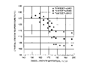
1 0 Fig. 1 is a graph showing relationships
between the crystallization temperature Tc and
dissolution temperature Ts of solutions of a vinylidene
fluoride homopolymer (weight average molecular weight:
3.62 x 10⁵) in diethyl phthalate (DEP).
1 5 Fig. 2 is an illustration showing a
relationship between the crystallization temperature Tc
and dissolution temperature Ts of a solution of the
vinylidene fluoride homopolymer or copolymer in a
solvent system, and a temperature range in which the
2 0 percolation structure can be formed.
Fig. 3 is a graph showing relationships
between dissolution temperature Ts and a) the porosity
(o), b) breaking strength (Kgf/cm') and c) breaking
extension (%) of hollow fiber type microporous
2 5 membranes.
Fig. 4 is an illustration showing a relation-
ship between a cloud point curve and crystallization
CA 02322855 2000-09-06
curves which are different in position at different
dissolution temperatures.
Fig. 5A, Fig. 5B and Fig. 5C are scanning
electron micrographs of sections, respectively, of
5 microporous membranes at different dissolution
temperatures Ts.
Fig. 6A, Fig. 6B and Fig. 6C are scanning
electron micrographs of sections, respectively, of
microporous membranes having various spherical-particle
10 network structures.
Figs. 7A to 7I are scanning electron
micrographs of the surfaces, respectively, of
microporous membranes obtained by using various cooling
media.
1 5 BEST MODE FOR CARRYING OUT THE INVENTION
The present invention is explained below in
detail.
The internal structure of a microporous
membrane is a structure observed by investigating any
2 0 section (a vertical section in most cases) of the
microporous membrane by a scanning electron microscope
or the like from a direction perpendicular to the
section. The structure of the surface layer of the
microporous membrane is a structure observed by
2 5 investigating the surface of the microporous membrane by
a scanning electron microscope or the like from a
direction perpendicular to the surface.
CA 02322855 2000-09-06
16
The microporous membrane of the present
invention is produced by forming a two-phase gel by
cooling either a solution consisting of the above-
mentioned vinylidene fluoride homopolymer or copolymer
and a solvent capable of forming a microporous membrane
having the percolation structure or a solvent capable of
permitting observation of planar liquid-liquid
interface, or a solution consisting of the vinylidene
fluoride homopolymer or copolymer, a solvent capable of
1 0 forming a microporous membrane having the percolation
structure or a solvent capable of permitting observation
of planar liquid-liquid interface, and the miscible
resin.
The two-phase gel referred to here is composed
1 5 of a polymer-rich phase having a high concentration of
the vinylidene fluoride homopolymer or copolymer and a
polymer-lean phase having a low concentration of said
homopolymer or copolymer, and contains a large volume of
the above-mentioned solvent capable of forming a
2 0 microporous membrane having the percolation structure or
solvent capable of permitting observation of planar
liquid-liquid interface. The solvent cannot be removed
from the two-phase gel referred to herein without using
the volatile liquid described hereinafter. For example,
2 5 cooling with a liquid cooling medium does not replace
the solvent with the liquid cooling medium to remove the
solvent.
In general, when a polymer solution is allowed
CA 02322855 2000-09-06
17
to stand at any temperature in a temperature range
corresponding to a two-phase region which is below the
cloud point temperature of the polymer solution and
above the crystallization temperature of a polymer-rich
phase, a typical example of the liquid-liquid interface
between the polymer-rich phase and a polymer-lean phase
observed is planar as described, for example, in Fig. 1.
2 of K. KAMIDE "THERMODYNAMICS OF POLYMER SOLUTIONS -
PHASE EQUILIBRIA AND CRITICAL PHENOMENA-" (ELSEVIER,
1 0 1990). The liquid-liquid interface is observed by a
standing method, for example, in the following manner.
A dispersion (or a liquid swollen product) in a solvent
of a polymer weighed so as to have each predetermined
polymer weight fraction is sealed in a sample tube under
nitrogen and heated together with the sample tube in a
high-temperature thermostat (for example, TAMSON BATH
TV7000, Netherland) filled with silicone oil to prepare
a solution. This dissolution by heating is carried out
by heating the sample tube for 6 to 24 hours at a
2 0 temperature (for example, 240°C) at which it is
considered that the contents of the sample tube assume a
one-phase state. After the uniform one-phase state of
the solution is visually confirmed, the solution is
cooled to an observation temperature, and the phase
2 5 state is observed after standing at this temperature for
10 to 48 hours. When the observation temperature is
lower than the cloud point temperature, namely, when the
solution is in a two-phase region, liquid-liquid phase
CA 02322855 2000-09-06
18
separation is observed.
When the phase state of a solution system
using the solvent capable of forming a microporous
membrane having the percolation structure according to
the present invention is observed by the standing
method, the separated states of a phase rich in the
vinylidene fluoride homopolymer or copolymer and a phase
lean in the vinylidene fluoride homopolymer or copolymer
are visually observed, but no planar interface is
1 0 formed. Moreover, in some cases, the liquid-liquid
interface between the phase rich in the vinylidene
fluoride homopolymer or copolymer and the phase lean in
the homopolymr or copolymer is difficult to observe
visually. In such a case, the solution before cooling
looks uniform when visually observed, but there is a
possibility that the solution may contain fine crystals
of the homopolymer or copolymer dispersed therein as
described hereinafter. When such a solution is cooled,
the whole solution becomes whitely turbid and looks
2 0 gelatinized. As to the reason why no liquid-liquid
interface is visually observed, there is a hypothesis
that gelation and liquid-liquid phase separation compete
with each other, or a conjecture that the polymer-lean
phase also contains the homopolymer or copolymer in such
2 5 an amount that crystallization thereof is observed.
When the observation of the liquid-liquid interface is
thus difficult, the presence of the polymer-lean phase
and the polymer-rich phase can be confirmed in some
CA 02322855 2000-09-06
19
cases by tilting a sample tube in which the polymer
solution is allowed to stand. That is, since the
polymer-rich phase has a higher viscosity than does the
polymer-lean phase, these two liquids different in
viscosity, can be distinguished by tilting the vessel.
The planar liquid-liquid interface is
exceptionally observed, and only in this exceptional
case, the percolation structure is formed even when a
two-phase gel is formed by cooling a solution obtained
1 0 by uniform one-phase dissolution at a high temperature.
In the present invention, the term "solvent capable of
permitting observation of planar liquid-liquid
interface" is defined as a solvent which permits
observation of the planar liquid-liquid interface
1 5 between a phase rich in the vinylidene fluoride
homopolymer or copolymer and a phase lean in the
vinylidene fluoride homopolymer or copolymer by the
standing method.
The average pore size measured by the half-dry
2 0 method of the microporous membrane of the present
invention ranges from 0.005 to 5 a m, and within this
range, the microporous membrane can be suitably used as,
for example, a filter for filtration of a liquid or a
gas. When the average pore size is more than 5 ~ m, the
2 5 number of structure defects such as pinholes is
increased, so that no microporous membrane having
satisfactory separating properties can be obtained.
When the average pore size is less than 0.005 ~ m, the
CA 02322855 2000-09-06
pore size is too small, so that the microporous membrane
cannot exhibit the porous membrane properties aimed at
by the present invention, such as those for water
treatment, virus removal, etc. When the microporous
5 membrane is used as a filter for water treatment, the
average pore size is preferably not more than 5 a m and
not less than 0.05 a m. In the case of water treatment,
when the average pore size is less than 0.05 a m, the
pore size is too small, resulting in a deteriorated
1 0 permeability. When the microporous membrane is used as
a filter for virus removal, its average pore size ranges
preferably from 0.005 to 0.1 a m, more preferably from
0.005 to 0.03 ~ m.
The ratio of the maximum pore size measured by
15 the bubble point method to the average pore size
measured by the half-dry method of the microporous
membrane of the present invention is 2.0 or less,
preferably 1.5 or less. Since this ratio of the maximum
pore size to the average pore size is 2.0 or less, the
2 0 microporous membrane of the present invention is
characterized by its very excellent fractionating
properties in removal of impurities from a liquid or a
gas.
As described above, the microporous membrane
2 5 of the present invention has the following percolation
structure: the polymer phase forms an isotropic network
structure by three-dimensional branching in arbitrary
directions, the voids are formed within an area
CA 02322855 2000-09-06
21
surrounded by the polymer phase of the network structure
and intercommunicate with one another, and the ratio of
the maximum pore size measured by the bubble point
method to the average pore size measured by the half-dry
method is 2.0 or less. On the other hand, spherical-
particle network structures in which a large portion of
a polymer phase is regarded substantially as spherical
particles (see, for example, Figs. 6A to 6C) are
different from the percolation structure according to
1 0 the present invention. In the spherical-particle
network structures, the polymer phase has joints at
contact points between spheres, resulting in
deteriorated mechanical properties.
Spherical-pore network structures and
1 5 ellipsoidal-pore network structures, in which most of
voids are regarded substantially as spherical pores or
ellipsoidal pores are also different from the
percolation structure according to the present
invention. In the spherical-pore network structures or
2 0 ellipsoidal-pore network structures, the pores are
joined together at contact points between spheres or
ellipsoids, resulting in a deteriorated permeability to
a liquid. The spherical-pore network structures or
ellipsoidal-pore network structures are called cellular
2 5 structures in some cases because they look like
structures composed of an assembly of spherical or
ellipsoidal cells.
As described above, the structure of the
CA 02322855 2000-09-06
22
isotropic, skinless and porous poly(vinylidene fluoride)
membrane disclosed in JP-A-7-265674 is also different
from the percolation structure according to the present
invention. A wet casting technique, i.e., the wet
membrane-producing technique is employed in JP-A-265674
and a microporous membrane obtained by the wet membrane-
producing technique is poor in mechanical strength as
described above.
In such a wet membrane-producing technique, a
1 0 membrane is produced by immersing a homogeneous solution
consisting of a polymer and a single or mixed solvent
therefor in a solidifying medium consisting of a single
or mixed non-solvent. In this case, in the solidifying
medium, phase separation between a polymer-rich phase
1 5 having a high concentration of the vinylidene fluoride
homopolymer or copolymer and a polymer-lean phase having
a low concentration of the homopolymer or copolymer
occurs from a portion of the solution where the solution
is in contact with the non-solvent, and the phase
2 0 separation propagates gradually inside the solution.
However, after the phase separation, instant replacement
of the solvent with the non-solvent takes place, so that
the polymer-lean phase diffuses into the non-solvent and
that the solvent is removed from the polymer-rich phase.
2 5 Thus, desolvation is finally achieved, resulting in the
solidification of the polymer and the formation of a
membrane structure.
In the wet membrane-producing technique, an
CA 02322855 2000-09-06
23
isotropic structure is attained when the precipitating
capability of the non-solvent is low. When the
precipitating capability of the non-solvent is low,
relatively slow desolvation occurs and hence no surface
layer is formed. By contrast, when the precipitating
capability of the non-solvent is high, a structure
comprising non-isotropic macro-voids and a dense skin
layer is formed which is another typical structure
formed by the wet membrane-producing technique. The
1 0 reason is that when the precipitating capability is
high, a skin is formed at first and rapid desolvation
occurs owing to permeation phenomenon through the skin.
On the other hand, in the process of the
present invention, when the homogeneous solution is
1 5 cooled, the homopolymer or copolymer is solidified by
crystallization, so that a gel-like shaped product
composed of a two-phase gel is formed. No desolvation
occurs in the process of the present invention.
The network structure according to the present
2 0 invention, i.e., the isotropic network structure formed
by three-dimensional branching by forming a two-phase
gel by cooling contributes to effects such as a high
elongation, a high virus-removing capability, a high
water permeability, a high ionic conductivity, a high
2 5 charging efficiency, etc.
That is, the microporous membrane of the
present invention has a homogeneous structure and is
excellent in permeability to a fluid, separation
CA 02322855 2000-09-06
24
properties in separating fine particles from the fluid,
mechanical properties and chemical resistance. The
excellence in liquid permeability means that said
microporous membrane is superior in liquid permeability
to a membrane having the same average pore size as that
of said microporous membrane. A microporous membrane
having an excellent liquid permeability is advantageous,
for example, in that a membrane module can be made
compact because the microporous membrane has a high
throughput capacity per unit membrane area.
The structure of the surface layer of the
microporous membrane of the present invention is the
same as the internal structure in some cases or
different from the internal structure in other cases
when observed by a scanning electron microscope.
Whether said structure is the same as or different from
the internal structure, the average pore size measured
by scanning electron microscopy of the surface layer can
be adjusted so as to be the same as or larger than the
2 0 average pore size measured by scanning electron
microscopy of the internal structure, by choosing proper
production conditions. Owing to this adjustment, the
vinylidene fluoride homopolymer or copolymer microporous
membrane of the present invention, having the
2 5 percolation structure as the internal structure, can
exhibit the microporous membrane properties aimed at by
the present invention. When the average pore size
measured by scanning electron microscopy of the surface
CA 02322855 2000-09-06
layer is larger than the average pore size measured by
scanning electron microscopy of the internal structure,
the surface layer can be designed to be effective as a
prefilter.
5 When the solution extruded by the use of an
extruder is cooled with air or rolls, the structure of
the surface layer is the same as the internal structure
when observed by a scanning electron microscope. In
this case, the average pore size of the surface layer
10 can be increased by employing a cooling-temperature
gradient. When the extruded solution is cooled with
air, the cooling-temperature gradient can be employed,
for example, by varying the temperature of cold air
blown against the extruded solution. When the extruded
1 5 solution is cooled with rolls, the cooling-temperature
gradient can be employed, for example, by making the
temperature of the first roll different from that of the
second or third roll. In both cases, the average pore
size of the surface layer tends to be increased when the
2 0 cooling temperature at a portion near the extrusion
orifice of the solution is set at a higher temperature.
When the solution extruded by the use of an
extruder is cooled with a liquid cooling medium, the
structure of the surface layer is different from the
2 5 internal structure when observed by a scanning electron
microscope. In this case, the average pore size of the
surface layer can be increased by properly choosing the
cooling medium, as described hereinafter.
CA 02322855 2000-09-06
26
When the average pore sizes measured by
scanning electron microscopy of the surface layer and
the internal structure are different, the thickness of
the surface layer is not less than 0.1 a m and usually
not more than 3 a m, whether the structure of the surface
layer is different from or the same as the internal
structure when observed by a scanning electron
microscope. When the average pore sizes are measured by
scanning electron microscopy, an image processor is
1 0 utilized as described hereinafter.
The present invention also includes a case
where the average pore size measured by scanning
electron microscopy of the surface layer on at least one
side of the microporous membrane is smaller than the
1 5 average pore size measured by scanning electron
microscopy of the internal structure. In this case, the
surface layer denser than the internal structure has the
effect of preventing impurities in a liquid or a gas
from intruding into the membrane. The thickness of the
2 0 surface layer in this case is also not less than 0.1 ~ m
and usually not more than 3 a m. The average pore size
of said denser surface layer is usually not less than
0.001 ~ m and not more than 0.1 a m.
In the present invention, the weight average
2 5 molecular weight of the vinylidene fluoride homopolymer
or copolymer is 1 x 10⁵ or more. When the weight average
molecular weight is less than 1 x 10⁵, the viscosity of a
solution of the homopolymer or copolymer is
CA 02322855 2000-09-06
27
disadvantageously low for forming a gel-like porous
material, and the resulting microporous membrane
possesses deteriorated mechanical properties. The
weight average molecular weight of said vinylidene
fluoride homopolymer or copolymer is preferably 3 x 10⁵
to 2 x 10⁶, and a mixture of two or more vinylidene
fluoride homopolymer or copolymers having different
weight average molecular weights may be used.
Examples of the vinylidene fluoride
1 0 homopolymer or copolymer used in the present invention
are vinylidene fluoride homopolymers and vinylidene
fluoride copolymers. As the vinylidene fluoride
copolymers, there are used copolymers of vinylidene
fluoride and at least one member selected from the group
1 5 consisting of ethylene tetrafluoride, propylene
hexafluoride, ethylene trifluoride chloride and
ethylene. The vinylidene fluoride homopolymers are
especially preferable. Mixtures of two or more of these
vinylidene fluoride homopolymers or copolymers may also
2 0 be used.
If necessary, various additives such as
antioxidants, ultraviolet absorbers, lubricants, anti-
blocking agents, etc. may be added to the vinylidene
fluoride homopolymer or copolymer so long as they do not
2 5 defeat the object of the present invention.
An example of process for producing the
vinylidene fluoride homopolymer or copolymer microporous
membrane of the present invention is explained below.
CA 02322855 2000-09-06
28
In the present invention, a starting solution
of the vinylidene fluoride homopolymer or copolymer is
prepared by heating the vinylidene fluoride homopolymer
or copolymer and a solvent capable of forming a
microporous membrane having the percolation structure,
in a weight ratio of 10 . 90 to 60 . 40 at a temperature
at which the percolation structure can be formed, to
dissolve the vinylidene fluoride homopolymer or
copolymer.
1 0 Another starting solution of the vinylidene
fluoride homopolymer or copolymer can be prepared by
heating the vinylidene fluoride homopolymer or copolymer
and a mixture of a solvent capable of forming a
microporous membrane having the percolation structure
and the miscible resin (hereinafter referred to as
~~solvent/miscible resin mixture"), in a weight ratio of
10 . 90 to 60 . 40 and in proportions satisfying the
following conditions: the total amount of the vinylidene
fluoride homopolymer or copolymer and the miscible resin
2 0 is 60 wt% or less based on the weight of the resulting
solution, and the weight ratio of the vinylidene
fluoride homopolymer or copolymer to the miscible resin
is 40 . 60 to 90 . 10; and thereby dissolving the
vinylidene fluoride homopolymer or copolymer and
2 5 miscible resin.
Fig. 1 shows relationships between the
crystallization temperature Tc and dissolution
temperature Ts of solutions of a vinylidene fluoride
CA 02322855 2000-09-06
29
homopolymer (weight average molecular weight: 3.62 x 10⁵)
in diethyl phthalate (DEP). The weight fractions of the
vinylidene fluoride homopolymer are 30 wt% (0), 35 wt~
(~) and 40 wto (D). At all the weight fractions, the
crystallization temperature Tc falls with a rise in the
dissolution temperature Ts and becomes substantially
constant at a dissolution temperature Ts of about 178°C
or higher. In this case, in a range of Ts < 178°C, there
is a possibility that the solution may contain fine
1 0 crystals of the polymer dispersed therein. It can also
be speculated that the number of fine crystals per unit
volume increases with a lowering of Ts in a range of Ts
< 178°C.
Fig. 2 is a schematic illustration showing a
1 5 relationship between the crystallization temperature Tc
and dissolution temperature Ts of a solution of the
vinylidene fluoride homopolymer or copolymer in a
solvent capable of forming a microporous membrane having
the percolation structure. Fig. 2 also shows a
2 0 temperature range in which the percolation structure can
be formed.
The percolation structure is densified with a
lowering of the dissolution temperature in the
temperature range in which the percolation structure can
2 5 be formed. From a solution obtained by dissolution at a
temperature below the temperature above which the
percolation structure can be formed, only a non-porous
shaped product can be obtained, resulting in a markedly
CA 02322855 2000-09-06
decreased porosity. When the dissolution temperature is
further lowered, no homogeneous solution can be
obtained. From a solution obtained by dissolution at a
temperature above the temperature range in which the
5 percolation structure can be formed, only a shaped
product having a coarse internal structure can be
obtained, resulting in remarkably decreased mechanical
strength and elongation. When the internal structure is
coarsened, the average pore size is increased and
1 0 moreover, the pore size distribution is widened. That
is, the ratio of the maximum pore size measured by the
bubble point method to the average pore size measured by
the half-dry method becomes more than 2Ø
Fig. 3 shows examples of these phenomena.
1 5 Fig. 3, a), b) and c) show relationships between each of
the porosity, breaking strength and breaking extension,
respectively, of vinylidene fluoride homopolymer or
copolymer microporous membranes produced at different
dissolution temperatures Ts, and the dissolution
2 0 temperatures Ts. The microporous membranes of Ts = 135,
140, 145, 150, 155 and 160°C were prepared by the
processes described in Comparative Example 7, Example 9,
Example 7, Example 8, Comparative Example 8 and
Comparative Example 9, respectively. From Fig. 3, a),
2 5 it can be seen that the porosity is markedly decreased
at 135°C or lower. From Fig. 3, b) and Fig. 3, c), it
can be seen that the breaking strength and the breaking
extension are markedly decreased at 155°C or higher. In
CA 02322855 2000-09-06
31
this case, according to the definition, T1 = 137.5°C and
Tu = 152.5°C, so that (Tu - T1) > 0. Therefore, DEP is
the solvent capable of forming a microporous membrane
having the percolation structure defined in (B). In
addition, 137.5°C~Ts~152.5°C is a temperature range in
which the percolation structure can be formed.
These phenomena are qualitatively explained
below with reference to the schematic illustration in
Fig. 4 which shows the influences of the dissolution
temperature on the crystallization temperature and a
cloud point curve.
Here, the cloud point curve is a curve
obtained by plotting the cloud point temperature against
the polymer concentration. When the cloud point
1 5 temperature is not lower than the crystallization
temperature, the solution is in a homogeneous one-phase
state in the case where the solution temperature exceeds
the cloud point temperature. By contrast, when the
solution temperature is not higher than the cloud point
2 0 temperature and not lower than the crystallization
temperature, the solution undergoes liquid-liquid phase
separation into two phases, i.e., a polymer-rich phase
having a high polymer concentration and a polymer-lean
phase having a low polymer concentration. When the
2 5 solution is cooled to a temperature not higher than the
crystallization temperature, the polymer is
crystallized, so that the solution is solidified.
In Fig. 4, the axis of ordinate refers to
CA 02322855 2000-09-06
32
temperature and the axis of abscissa to the
concentration (for example, weight fraction) of the
vinylidene fluoride homopolymer or copolymer, and the
alternate long and two short dashes line is a cloud
point curve. However, the cloud point curve in this
case is on the low-temperature side as compared with the
crystallization lines, i.e., the solidification lines,
and hence is not observed in practice. On the basis of
a thermodynamic reasoning by analogy, it was assumed
that the cloud point curve is present in the position of
the alternate long and two short dashes line. Here, the
region on the low-temperature side under the cloud point
curve can be considered as a two-phase separation
region, as in the case of a system which undergoes
1 5 liquid-liquid phase separation.
In Fig. 4, D shows high-temperature
dissolution under a condition of Ts > Tu, ~ shows
dissolution at a dissolution temperature Ts at which the
percolation structure can be formed and which satisfies
2 0 a condition of T1~ Ts~ Tu (this dissolution is expressed
in the word "intermediate" in Fig. 4), and ~ shows low-
temperature dissolution under a condition of Ts < T1.
The alternate long and short dash line, the broken line
and the solid line are crystallization lines in the case
2 5 of the high-temperature dissolution, the dissolution at
a dissolution temperature at which the percolation
structure can be formed, and the low-temperature
dissolution, respectively.
CA 02322855 2000-09-06
33
As previously described, in the case of the
dissolution at a temperature lower than T1 (~), only a
non-porous material can be obtained, resulting in a
markedly decreased porosity. In this case, as can be
seen from Fig. 4, the cloud point curve is sufficiently
on the low-temperature side as compared with the
crystallization line, and it is conjectured that uniform
gelation due to crystallization becomes dominant over
two-phase separation, so that the non-porous material is
1 0 obtained. In the case of the dissolution at a
temperature higher than Tu (D), the crystallization
temperature Tc is low, resulting in a coarsened
structure and hence markedly deteriorated mechanical
properties. In this case, as shown in Fig. 4, a part of
1 5 the cloud point curve is on the high-temperature side as
compared with the crystallization line, and it is
conjectured that the coarsened structure is due to
enhancement of the influence of two-phase separation.
In the temperature range (~) intermediate between the
2 0 above two temperature ranges, the percolation structure
defined in (A) is formed. As the reason for this
formation, a mechanism comprising completion between
gelation and liquid-liquid phase separation is thought
of .
2 5 When a solvent capable of forming a
microporous membrane having the percolation structure is
used, a temperature range in which the percolation
structure can be formed varies depending on combination
CA 02322855 2000-09-06
34
of the vinylidene fluoride homopolymer or copolymer and
the solvent. Even when the same vinylidene fluoride
homopolymer or copolymer and the same solvent are used,
the temperature range varies depending on their weight
fractions. In addition, even when the same combination
of the vinylidene fluoride homopolymer or copolymer and
the solvent and the same weight fractions thereof are
employed, the temperature range in which the percolation
structure can be formed tends to shift to low
temperatures in the case of dynamic formation of the
microporous membrane such as membrane production by
extrusion using an extruder, as compared with a
relatively static formation of the microporous membrane
such as membrane production using a press. That is, the
1 5 temperature range in which the percolation structure can
be formed varies depending also on a production process
of the membrane. In the membrane production using a
press, a sample obtained by heating and mixing the
vinylidene fluoride homopolymer or copolymer and the
2 0 solvent and cooling the mixture to room temperature, is
subjected to redissolution at a constant dissolution
temperature by the use of a hot press to be formed into
a flat membrane or the like. In the case of such press
membrane production, the temperature at the redissolu-
2 5 tion using the hot press determines whether the
percolation structure is formed or not. In other words,
the solution does not memorize its heat history and the
final dissolution temperature determines the structure
CA 02322855 2000-09-06
of the membrane.
Also from the fact that as shown in Fig. 3, a
high porosity can be maintained while maintaining high
strength and elongation, and the significance of
5 formation of the percolation structure can be confirmed.
In addition, the above-mentioned solvent is required to
maintain a liquid state at a melt shaping temperature,
and to be inert.
As the above-mentioned solvent capable of
1 0 forming a microporous membrane having the percolation
structure, there are mentioned a single solvent such as
phthalic acid esters (e. g. dimethyl phthalate, diethyl
phthalate, dibutyl phthalate, dioctyl phthalate,
diisodecyl phthalate and tridecyl phthalate), benzoic
1 5 acid esters (e. g. methyl benzoate and ethyl benzoate),
sebacic acid esters (e. g. octyl sebacate), adipic acid
esters (e. g. dioctyl adipate), trimellitic acid esters
(e. g. trioctyl trimellitate), phosphoric esters (e. g.
tributyl phosphate and tricresyl phosphate) and ketones
2 0 (e.g. acetophenone), and mixed solvents thereof. In the
solvents mentioned above, the alkyl groups may include
their various isomers. In the present invention, there
can also be used a mixed solvent obtained by mixing the
above-exemplified single solvent or mixed solvent and a
2 5 good solvent (e. g. acetone, tetrahydrofuran, methyl
ethyl ketone, dimethylformamide, dimethylacetamide,
dimethyl sulfoxide or N-methylpyrrolidone) or a non-
solvent (e. g. water), and adjusting the dissolving
CA 02322855 2000-09-06
36
properties so that the resulting solvent may be capable
of forming a microporous membrane having the percolation
structure. However, it is impossible in the present
invention to use a combination of the solvent and a
cooling medium which causes the replacement of the
solvent with the cooling medium in a cooling bath to
achieve desolvation finally. When any of the above
solvents capable of forming a microporous membrane
having the percolation structure are used, no planar
liquid-liquid interface between a phase rich in the
vinylidene fluoride homopolymer or copolymer and a phase
lean in the vinylidene fluoride homopolymer or
copolymer, is observed by the standing method.
The miscible resin includes methacrylic ester
1 5 resins, acrylic ester resins, poly(1,4-butylene-
adipate)s, polyvinyl acetates, poly(vinyl-
pyrrolidone)s, etc. Of these, methyl methacrylate
resins and methyl methacrylate copolymers are preferably
used. As the methyl methacrylate copolymers, there can
2 0 be mentioned copolymers with comonomers such as methyl
acrylate, styrene, a-methylstyrene, methacrylic acid,
malefic anhydride, etc.
As the solvent capable of permitting the
observation of planar liquid-liquid interface, there can
2 5 be mentioned mixed solvents of f -caprolactone and
diethylhexyl adipate in a weight ratio of 20 . 80 to
40 . 60. No planar liquid-liquid interface is observed
when the proportion of F-caprolactone is less than 20
CA 02322855 2000-09-06
37
wto or more than 40 wt%. The proportion of F-
caprolactone ranges preferably from 25 to 38 wt$.
When the solvent capable of forming a
microporous membrane having the percolation structure is
used for the dissolution by heating, the dissolution is,
as described above, carried out while stirring a mixture
consisting of the vinylidene fluoride homopolymer or
copolymer and the solvent capable of forming a
microporous membrane having the percolation structure,
or a mixture consisting of the vinylidene fluoride
homopolymer or copolymer, the solvent capable of forming
a microporous membrane having the percolation structure,
and the miscible resin, at a temperature at which the
percolation structure can be formed. This temperature
may be set in a range of T1°C to Tu°C, preferably (T1 +
2)°C to (Tu - 2)°C, depending on the kinds of vinylidene
fluoride homopolymer or copolymer, solvent and miscible
resin used.
The concentration of the vinylidene fluoride
2 0 homopolymer or copolymer in the above-mentioned mixture
is 10 to 60 wto, preferably 10 to 40 wt%, more
preferably 10 to 30 wto, though a concentration thereof
at which the dissolution is possible varies depending on
the dissolving properties of the solvent. When the
2 5 concentration is less than 10 wt%, the viscosity of the
solution is low, resulting in a low moldability and a
low mechanical strength of a shaped product. On the
other hand, when the concentration is more than 60 wt%,
CA 02322855 2000-09-06
38
the preparation of a homogeneous solution becomes
difficult and the percolation structure becomes
difficult to obtain.
When the mixture consisting of the vinylidene
fluoride homopolymer or copolymer, the solvent capable
of forming a microporous membrane having the percolation
structure, and the miscible resin, is selected to be
dissolved by heating, the following additional
conditions should be satisfied: the total concentration
1 0 of the vinylidene fluoride homopolymer or copolymer and
the miscible resin is 60 wto or less, and the weight
ratio of the vinylidene fluoride homopolymer or
copolymer to the miscible resin is 40 . 60 to 90 . 10.
When the total concentration of the vinylidene fluoride
1 5 homopolymer or copolymer and the miscible resin is more
than 60 wto, the preparation of a homogeneous solution
becomes difficult and the percolation structure becomes
difficult to obtain. When the proportion of the
miscible resin is more than 60 wto based on the total
2 0 weight of the vinylidene fluoride homopolymer or
copolymer and the miscible resin, the crystallinity of
the vinylidene fluoride homopolymer or copolymer is
remarkably deteriorated, resulting in a low mechanical
strength of a shaped product. By contrast, when the
2 5 proportion of the miscible resin is less than 10 wt%
based on the total weight of the vinylidene fluoride
homopolymer or copolymer and the miscible resin, no
effect of the addition of the miscible resin can be
CA 02322855 2000-09-06
39
expected.
When the mixture consisting of the vinylidene
fluoride homopolymer or copolymer, the solvent capable
of forming a microporous membrane having the percolation
structure, and the miscible resin is selected in the
dissolution by heating, the production of a shaped
product by the stretching described in v) or vi) results
in a markedly improved water permeability. It can be
speculated that the presence of the miscible resin
properly reduces the crystallinity of the vinylidene
fluoride homopolymer or copolymer to facilitate the
production of structural defects and that the
probability of the presence of pinholes is enhanced by
destruction caused by the stretching.
1 5 When a mixture consisting of the vinylidene
fluoride homopolymer or copolymer and a solvent capable
of permitting observation of planar liquid-liquid
interface is selected in the dissolution by heating, it
is necessary to carry out uniform one-phase dissolution
2 0 at a dissolution temperature Ts of 10°C or higher than
the cloud point temperature determined by the standing
method. The dissolution temperature Ts is preferably
20°C or more higher than the cloud point temperature
determined by the standing method. In order to inhibit,
2 5 for example, pyrolysis of the solvent and the like, the
dissolution temperature Ts is preferably ((the cloud
point temperature determined by the standing method) +
40°C) or lower. For example, when a mixed solvent of F-
CA 02322855 2000-09-06
caprolactone and diethylhexyl adipate in a weight ratio
of 25 . 45 is used as the solvent capable of permitting
observation of planar liquid-liquid interface, the cloud
point temperature of a system consisting of a poly-
5 (vinylidene fluoride) with a weight average molecular
weight Mw of 1.18 x 10⁶, ~-caprolactone and diethylhexyl
adipate in a ratio of 30 . 25 :45 is 220°C. Therefore,
the dissolution temperature Ts is preferably not higher
than 260°C and not lower than 230°C.
10 Next, the heated solution obtained from any of
the above-mentioned mixtures is shaped by extrusion
through a die. The die may be properly chosen. If
necessary, a hollow die, T-die, double-cylindrical
inflation die, etc. can be used. When the solvent
1 5 capable of forming a microporous membrane having the
percolation structure is used, the extrusion temperature
is properly set in a range of T1°C to Tu°C depending on
the kind of the solvent. When the solvent capable of
permitting observation of planar liquid-liquid interface
2 0 is used, it is preferable to set the extrusion
temperature properly in a range of a temperature 10°C
higher than the cloud point temperature determined by
the standing method to a temperature 40°C higher than the
cloud point temperature.
2 5 The solution extruded through the die is
cooled to become a gel-like shaped product composed of a
two-phase gel. For the cooling, the following methods,
for example, can be adopted: cooling with air, cooling
CA 02322855 2000-09-06
41
with a roll, and a method of bringing the solution into
direct contact with a liquid cooling medium.
When a planar membrane is obtained by
extruding the solution through a T-die of the like, the
cooling method using air or the cooling method using a
roll is often adopted. In this case, a vinylidene
fluoride homopolymer or copolymer microporous membrane
is obtained in which the structure of the surface layer
is the same as the internal structure when observed by a
1 0 scanning electron microscope, and the average pore size
measured by scanning electron microscopy of the surface
layer is usually the same as or larger than the average
pore size measured by scanning electron microscopy of
the internal structure.
When a hollow membrane is obtained by
extruding the solution through a hollow die, the method
of bringing the solution into direct contact with a
liquid cooling medium is advantageous for stabilizing
the hollow shape of section and section sizes of the
2 0 membrane. In the case of the air-cooling or the cooling
with a roll, the shape of section of hollow fiber is
often lost because the mixture of the vinylidene
fluoride homopolymer or copolymer and the solvent has a
low viscosity. Also when a die other than hollow dies,
2 5 such as a T-die is used, the solution can be brought
into direct contact with a liquid cooling medium. In
the case of the direct contact with a liquid cooling
medium, the solvent capable of forming a microporous
CA 02322855 2000-09-06
42
membrane having the percolation structure is preferably
used as the cooling medium.
As the cooling medium which is the solvent
capable of forming a microporous membrane having the
percolation structure, there are mentioned a single
cooling medium such as phthalic acid esters (e. g.
dimethyl phthalate, diethyl phthalate, dibutyl
phthalate, dioctyl phthalate and diisodecyl phthalate),
benzoic acid esters (e. g. methyl benzoate and ethyl
benzoate), sebacic acid esters (e. g. octyl sebacate),
adipic acid esters (e. g. dioctyl adipate), trimellitic
acid esters (e. g. trioctyl trimellitate), phasphoric
esters (e. g. tributyl phosphate and tricresyl phosphate)
and ketones (e. g. acetophenone), and mixed cooling media
1 5 thereof. In the cooling media mentioned above, the
alkyl groups may include their various isomers. In the
present invention, there can also be used as the cooling
medium a mixed solvent obtained by mixing the above-
exemplified single cooling medium or mixed cooling
2 0 medium and a good solvent (e. g. acetone, tetrahydro-
furan, methyl ethyl ketone, dimethylformamide,
dimethylacetamide, dimethyl sulfoxide or N-
methylpyrrolidone) or a non-solvent (e.g. water), and
adjusting the dissolving properties so that the
2 5 resulting solvent may be capable of forming a
microporous membrane having the percolation structure.
However, as described in the explanation of the solvent,
it is impossible in the present invention to use a
CA 02322855 2000-09-06
43
combination of the solvent and the cooling medium which
causes the replacement of the solvent with the cooling
medium in a cooling bath to achieve desolvation finally.
The cooling temperature is preferably (Tm -
50°C) or lower. Here, Tm is the melting point of the
vinylidene fluoride homopolymer or copolymer in the
mixture of the vinylidene fluoride homopolymer or
copolymer and the solvent. The melting point Tm becomes
lower with a decrease in the concentration of the
1 0 vinylidene fluoride homopolymer or copolymer (melting
point lowering phenomenon).
When a cooling medium having a low affinity
for the vinylidene fluoride homopolymer or copolymer is
used, the surface layer of the resulting vinylidene
fluoride homopolymer or copolymer microporous membrane
has a skin-like structure or an assembly structure
formed of a granular material, so that the porosity of
the surface is decreased in some cases. As described
above, the average pore size of the surface layer can be
2 0 increased by properly selecting the cooling medium.
Figs. 7A to 7I show scanning electron
micrographs of the surfaces, respectively, of
poly(vinylidene fluoride) microporous membranes obtained
by using various cooling media. For example, when the
2 5 cooling medium is dimethyl phthalate (DMP), diethyl
phthalate (DEP) or diethylhexyl phthalate (DOP), the
average pore size measured by scanning electron
microscopy (SEM average pore size) of the surface layer
CA 02322855 2000-09-06
44
is larger than SEM average pore size of the internal
structure. It is considered that the average pore size
of the surface layer is determined by the affinity of
the cooling medium for the vinylidene fluoride
homopolymer or copolymer. In the case where Tmloo> Tm3c
wherein Tmioo is the melting point of the vinylidene
fluoride homopolymer or copolymer in DSC and Tm3o is the
melting point in DSC of a mixture of the vinylidene
fluoride homopolymer or copolymer and any liquid in a
ratio of 30 . 70, it may be judged that the system
consisting of the vinylidene fluoride homopolymer or
copolymer, and the liquid shows a lowering of melting
point. It is considered that in such a system which
shows a lowering of melting point, the affinity of the
liquid for the vinylidene fluoride homopolymer or
copolymer is high. When the cooling medium is used as
such a liquid having a high affinity for the vinylidene
fluoride homopolymer or copolymer, the following
relation tends to hold:
2 0 (the average pore size measured by scanning
electron microscopy of the surface layer) > (the average
pore size measured by scanning electron microscopy of
the internal structure)
In other words, it is sufficient that a solvent capable
2 5 of causing the melting point lowering phenomenon in the
case of the vinylidene fluoride homopolymer or copolymer
is used as the cooling medium. However, when the
affinity is too high, the membrane surface is dissolved
CA 02322855 2000-09-06
to become non-porous. In order to avoid the formation
of the non-porous surface due to the dissolution, it is
necessary to use a cooling medium which satisfies a
condition of Tm3o > 100°C.
5 As shown in Figs. 7A to 7I, when the cooling
medium is diisodecyl phthalate (DIDP), tridecyl
phathalate (DTDP), water, ethylene glycol, decalin or
the like, the following relation holds:
(the SEM average pore size of the surface
10 layer) < (the SEM average pore size of the internal
structure)
Particularly when DTDP, decalin or the like is used, the
membrane surface becomes non-porous. Even in such a
case, it is possible to establish the following
1 5 relation:
(the average pore size measured by scanning
electron microscopy of the surface layer) > (the average
pore size measured by scanning electron microscopy of
the internal structure)
2 0 by forming pores with a diameter of about 1 a m in the
case of approximation to round pores by carrying out
stretching with a stretching residual strain of 100% or
less before or after removing the solvent by the use of
a volatile liquid. The stretching is more effective
2 5 when conducted after extracting the solvent.
The gel-like shaped product obtained is washed
with a volatile liquid miscible with the solvent to be
freed of the solvent. As the volatile liquid for the
CA 02322855 2000-09-06
46
washing, there can be used, for example, hydrocarbons
such as pentane, hexane, heptane, etc.; chlorinated
hydrocarbons such as methylene chloride, carbon
tetrachloride, etc.; fluorinated hydrocarbons such as
ethane trifluoride, etc.; ethers such as methyl ethyl
ether, diethyl ether, etc.; and ketones such as acetone,
methyl ethyl ketone, etc. The volatile liquids
mentioned above are properly selected depending on the
kind of the solvent used, and are used singly or as a
mixture thereof. The washing can be conducted, for
example, by a method comprising immersion in the
volatile liquid followed by extraction, a method
comprising showering the volatile liquid, or a
combination thereof. When the mixture consisting of the
1 5 vinylidene fluoride homopolymer or copolymer, the
solvent capable of forming a microporous membrane having
the percolation structure and the miscible solvent is
selected, it is preferable to use a volatile liquid with
which the solvent and the miscible resin can be washed
2 0 away at the same time.
Then, the microporous membrane is dried. As a
method for drying the microporous membrane, there are
mentioned methods such as drying by heating, air-drying
with hot air, or contacting with a heating roll.
2 5 For the purpose of improving the surface
porosity of the microporous membrane, namely, for the
purpose of increasing the average pore size measured by
scanning electron microscopy of the surface layer,
CA 02322855 2000-09-06
47
increasing the probability of the presence of
throughholes, and increasing the breaking strength, the
gel-like shaped product or the microporous membrane, or
both, can be stretched with a stretching residual strain
of 0 to 1000, preferably 10 to 1000, at such a draw
ratio that the above-mentioned structural character-
istics of the microporous membrane are retained. The
stretching of the gel-like shaped product or the
microporous membrane is conducted at a predetermined
ratio by a conventional tenter method, roll method,
rolling method, or a combination thereof. The
stretching may be either uniaxial stretching or biaxial
stretching. The biaxial stretching may be either
simultaneous or sequential lengthwise-and-crosswise
1 5 stretchings. In the case of the uniaxial stretching,
the term "stretching residual strain" used here means the
percentage of an increment in the length of a specimen
given by the stretching, based on the length of the
specimen before the stretching (the original length).
2 0 In the case of the biaxial stretching, the term means
the percentage of an increment in the area of a membrane
given by the stretching, based on the area of the
membrane before the stretching (the original area). For
limiting the stretching residual strain to 100 or less,
2 5 the draw ratio is 3 or less in the case of the uniaxial
stretching, and the draw ratio is 4 or less in terms of
area ratio in the case of the biaxial stretching, though
these ratios vary depending on conditions. The
CA 02322855 2000-09-06
48
stretching temperature for the gel-like shaped product
or the microporous membrane is 50°C or lower, preferably
25°C or lower. When the stretching temperature is higher
than 50°C, the stretching is not sufficiently effective.
When the gel-like shaped product is stretched,
the solvent is removed by the above-mentioned method
after the stretching, and the microporous membrane is
dried.
The microporous membrane thus obtained can be
1 0 heat-treated, for example, for attaining dimensional
stability. The heat-treatment temperature can be set at
any temperature not higher than (the melting temperature
of the vinylidene fluoride resin - 20°C) and not lower
than 50°C.
If necessary, the microporous membrane
obtained can be made hydrophilic by alkali treatment,
plasma irradiation, electron beam irradiation, y-ray
irradiation, corona treatment, impregnation with a
surfactant, surface graft, coating, or the like.
2 0 In addition, if necessary, the gel-like shaped
product or the microporous membrane can be subjected to
crosslinking by electron beam irradiation, y -ray
irradiation or the like.
The produced microporous membrane preferably
2 5 has a porosity of not more than 90o and not less than
30%, more preferably not more than 80% and not less than
50o, a breaking strength of 50 Kgf/cm2 or more, more
preferably 70 to 500 Kgf/cm2, a breaking extension of
CA 02322855 2000-09-06
49
1500 or more, more preferably 200 to 8000, a bubble
point measured by the bubble point method of 1 to 20
Kgf/cmz, and a water permeability of 200 to 10,000
liters/m~~hr~atm. Although the thickness of the
microporous membrane of the present invention can be
properly chosen depending on purposes, it is usually 20
to 1,000 a m, preferably 60 to 800 ~ m.
The microporous membrane of the present
invention and the gel-like shaped product composed of a
1 0 two-phase gel of the present invention obtained in the
production process of the microporous membrane can be
used as a precursor of an electrolyte support for a
solid electrolyte battery obtained by introducing an
electrolytic solution into the microporous membrane or
1 5 replacing the solvent in the gel-like shaped product
with an electrolytic solution.
Measurement items and measuring methods
employed in the present invention are as follows:
(1) Molecular weight and molecular weight
2 0 distribution: Weight average molecular weight Mw in
terms of polystyrene is measured by GPC. GPC measuring
apparatus; that manufactured by Tosoh Ltd., column;
GMHXL, solvent; DMF, column temperature; 40°C.
(2) Observation of the structure of the
2 5 surface layer of a microporous membrane and its internal
structure: The structure of surface layer of each
microporous membrane and its internal structure are
observed by the use of a scanning electron microscope
CA 02322855 2000-09-06
SEM (S-800A, mfd. by Hitachi Ltd.). Here, the term
"internal structure" means the structure of a section
obtained by severing the microporous membrane after
freezing which is observed from a direction
5 perpendicular to the section.
(3) Average pore size (u m) measured by
scanning electron microscopy: On a scanning electron
micrograph of the surface or a section of each
microporous membrane, 50 parallel straight lines are
1 0 drawn with an image processor (IP-1000PC, mfd. by Asahi
Kasei Kogyo K.K.), and the average length of segments
inside voids of straight lines passing the voids is
taken as the average pore size. The magnification and
the area of region were set so that any of the lines
1 5 might cross at least 10 voids. In the present
invention, there is utilized a 16 ,um (length) x 16 a m
(width) region in the photograph taken through an
electron microscope of 6000 magnifications, unless
otherwise specified.
2 0 (4) Thickness (u m) of a microporous membrane:
The average of arbitrarily selected 5 or more section
thickness values of each microporous membrane observed
by SEM is taken as the thickness of the microporous
membrane.
2 5 (5) Average pore size (u m) (half-dry method):
Measured by the use of ethanol according to ASTM F316-
86. In Examples and Comparative Examples, the simple
words "average pore size" mean an average pore size
CA 02322855 2000-09-06
51
measured by this method.
(6) Maximum pore size (u m) (bubble point
method): Measured by the use of ethanol according to
ASTM F316-86 and E128-61.
(7) Porosity (%): Porosity = (volume of voids
/ volume of microporous membrane) x 100.
(8) Breaking strength (Kgf/cm2) and breaking
extension (o): Measured for a hollow fiber type specimen
or a strip specimen of 10 mm in width according to ASTM
1 0 D882.
(9) Water permeability (liters/m'~hr~atm):
Measured by the use of pure water at 25°C and at a
differential pressure of 1 Kgf/cm'.
(10) Stretching residual strain (o):
Stretching residual strain = ((specimen length after
stretching - original length) / original length) x 100
(11) Melting point Tm (°C): A mixture of a
vinylidene fluoride homopolymer or copolymer and a
solvent is sealed up in a sealed type DSC container, and
2 0 a melting peak temperature measured by the use of DSC-
200 manufactured by Seiko Denshi Co., Ltd. (heating rate
5°C/min) is taken as the melting point.
(12) Crystallization temperature Tc (°C): A
mixture of a vinylidene fluoride homopolymer or
2 5 copolymer and a solvent is sealed up in a sealed type
DSC container, heated to a dissolution temperature Ts at
a heating rate of 5°C/min by the use of DSC-200
manufactured by Seiko Denshi Co., Ltd., maintained at
CA 02322855 2000-09-06
52
this temperature for 20 minutes, and then cooled at a
cooling rate of 2°C/min. A crystallization peak
temperature observed during the cooling is taken as the
crystallization temperature.
(13) Ionic conductivity (mS/cm): A sheet-like
electrolyte support is held between metal electrodes
(stainless steel sheets) to form an electrochemical
cell. By employing an alternating-current impedance
method comprising applying an alternating current
1 0 between the electrodes and measuring the resistance
component, the impedance is measured with Impedance
Meter Model 389 manufactured by EG & G Co., Ltd. The
ionic conductivity is calculated from a real-number
impedance intercept in a Cole-Cole plot.
The present invention is concretely explained
with the following examples.
Example 1
40 Parts by weight of a vinylidene fluoride
homopolymer having a weight average molecular weight
2 0 (Mw) of 3.62 x 10⁵ and 60 parts by weight of diethyl
phthalate (DEP) were mixed with heating at 160°C in a
twin-rotor kneader and then cooled to room temperature.
The resulting sample was subjected to redissolution to
be shaped into a flat membrane of 100 ~cm at 155°C with a
2 5 hot pressing machine, and then cooled with a pressing
machine at 20°C to obtain a sheet-like and gel-like
shaped product. The gel-like shaped product obtained by
CA 02322855 2000-09-06
53
the shaping was immersed in methylene chloride for 1
hour to extract DEP, and the residue was dried at room
temperature to obtain a microporous membrane. The
average pore size of this membrane was 0.1 a m, and a
photograph of the internal structure of the membrane is
shown in Fig. 5B. The membrane was uniaxially stretched
at a draw ratio of 150% at 20°C, followed by relaxation
at 20°C. In this case, the stretching residual strain
was 200. The ratio of the maximum pore size measured by
the bubble point method to the average pore size
measured by the half-dry method was 2.0 or less, and the
internal structure of the oriented film obtained was the
percolation structure.
Example 2
The process of Example 1 was repeated except
for conducting the shaping at 160°C with a pressing
machine. The average pore size of the resulting
membrane was 0.15 ~ m, and a photograph of the internal
structure of the membrane is shown in Fig. 5C. The
2 0 stretching residual strain of the resulting oriented
film was 300. The ratio of the maximum pore size
measured by the bubble point method to the average pore
size measured by the half-dry method was 2.0 or less,
and the internal structure was the percolation
2 5 structure.
CA 02322855 2000-09-06
54
Comparative Example 1
The process of Example 1 was repeated except
for conducting the shaping at 150°C with a pressing
machine. The internal structure of the resulting
membrane was non-porous as shown in Fig. 5A.
Example 3
The process of Example 1 was repeated except
for using 70 parts by weight of acetophenone in place of
60 parts by weight of DEP, conducting the kneading at
140°C, and conducting the shaping at 140°C with a
pressing machine. The average pore size of the
resulting membrane was 0.15 a m. The ratio of the
maximum pore size measured by the bubble point method to
the average pore size measured by the half-dry method
1 5 was 2.0 or less, and the internal structure was the
percolation structure.
Example 4
The process of Example 1 was repeated except
for using 70 parts by weight of dibutyl phthalate (DBP)
2 0 in place of 60 parts by weight of DEP, conducting the
kneading at 165°C, and conducting the shaping at 165°C
with a pressing machine. The average pore size of the
resulting membrane was 0.15 ~cm. The ratio of the
maximum pore size measured by the bubble point method to
2 5 the average pore size measured by the half-dry method
was 2.0 or less, and the internal structure was the
CA 02322855 2000-09-06
percolation structure.
Comparative Example 2
The process of Example 1 was repeated except
for using 55 parts by weight of y-butyrolactone (y-BL)
5 in place of 60 parts by weight of DEP, conducting the
kneading at 120°C, and conducting the shaping at 120°C
with a pressing machine. The internal structure of the
resulting membrane is a structure composed of connected
spherical particles as shown in Fig. 6A.
10 Comparative Example 3
The process of Comparative Example 2 was
repeated except for using ethylene carbonate (EC) in
place of y-BL, conducting the kneading at 150°C, and
conducting the shaping at 150°C with a pressing machine.
1 5 The internal structure of the resulting membrane is a
structure composed of connected spherical particles as
shown in Fig. 6B.
Comparative Example 4
The process of Comparative Example 3 was
2 0 repeated except for using propylene carbonate (PC) in
place of EC. The internal structure of the resulting
membrane is a structure composed of connected spherical
particles as shown in Fig. 6C.
CA 02322855 2000-09-06
56
Example 5
A gel-like shaped product obtained by
repeating the process of Example 1 except for changing
the amount of DEP to 70 parts by weight was subjected to
redissolution on a hot plate at 160°C, cooled with air at
20°C, and uninterruptedly immersed in methylene chloride
for 1 hour to extract DEP, and the residue was dried at
room temperature to obtain a microporous membrane. The
average pore size of this membrane was 0.1 a m and its
1 0 surface was porous as shown in Fig. 7A. The average
pore size measured by scanning electron microscopy of
the surface layer of the membrane was 1.2 times the
average pore size measured by scanning electron
microscopy of the internal structure. The ratio of the
maximum pore size measured by the bubble point method to
the average pore size measured by the half-dry method
was 2.0 or less, and the internal structure was the
percolation structure.
Example 6
2 0 The process of Example 5 was repeated except
for conducting the cooling in a cooling medium at 20°C.
As the cooling medium, there was used each of dimethyl
phthalate (DMP), DEP, diethylhexyl phthalate (DOP),
diisodecyl phthalate (DIDP), water and ethylene glycol
2 5 (EG). The surfaces of the membranes obtained by using
each of DMP, DEP, DOP, DIDP, water and EG were porous as
shown in Figs. 7B, 7C, 7D, 7E, 7G and 7H, respectively.
CA 02322855 2000-09-06
57
The average pore sizes measured by scanning electron
microscopy of the surface layers of the membranes shown
in Figs. 7B, 7C, 7D, 7E, 7G and 7H were 2.0 times, 1.5
times, 1.2 times, 1.0 times, 0.8 times and 0.5 times,
respectively, as large as the average pore sizes
measured by scanning electron microscopy of the internal
structures, respectively, of the membranes. As for
Figs. 7G and 7H, the average pore sizes of the membranes
were measured after removing the surface skin layers of
the membranes by utilizing the adhesive strength of an
adhesive tape. The average pore sizes of the membranes
shown in Figs. 7B, 7C, 7D and 7E are about 0.1 MM, and
the average pore sizes of the membranes shown in Figs.
7G and 7H were about 0.04 MM. The ratio of the maximum
pore size measured by the bubble point method to the
average pore size measured by the half-dry method was
2.0 or less for all the membranes, and the internal
structure of each membrane was the percolation
structure.
2 0 Comparative Example 5
The process of Example 5 was repeated except
for conducting the cooling in a cooling medium at 20°C.
As the cooling medium, each of tridecyl phthalate (DTDP)
and decalin was used. The surfaces of the membranes
2 5 obtained by using each of DTDP and decalin were non-
porous as shown in Fig. 7F and 7I, respectively. The
ratio of the maximum pore size measured by the bubble
CA 02322855 2000-09-06
58
point method to the average pore size measured by the
half-dry method after removing the surface skin layers
of the membranes by utilizing the adhesive strength of
an adhesive tape was 2.0 or less for the two membranes,
and the internal structure of each membrane was the
percolation structure.
Example 7
A mixture of 46.6 parts by weight of PVdF
having a Mw of 3.62 x 10⁵ and 53.4 parts by weight of DEP
1 0 was kneaded with heating at 145°C by means of a 35 mm ~
twin-screw extruder and extruded into a hollow fiber
through a hollow die with an inside diameter of 0.9 mm ~
and an outside diameter of 1.7 mm ~. In this case, in
order to stabilize the diameter of the hollow fiber, air
1 5 was allowed to flow inside the fiber at a rate of 10
ml/min, and the extruded hollow fiber was cooled by
immersion in a cooling medium bath of DOP to obtain a
gel-like shaped product. The hollow fiber type gel
obtained by the above shaping was immersed in methylene
2 0 chloride for 1 hour to extract DEP, and the residue was
dried at room temperature to obtain a hollow fiber
membrane. The hollow fiber membrane obtained had an
inside diameter of 0.84 mm, an outside diameter of 1.59
mm, a porosity of 54.6%, an average pore size of 0.14 a m.
2 5 and a maximum pore size of 0.21 a m. The ratio of the
maximum pore size to the average pore size was 1.50.
The hollow fiber membrane had a water permeability of
CA 02322855 2000-09-06
59
300 liters/ m~~hr~atm, a breaking strength of 139
Kgf/cm', and a breaking extension of 353$. The internal
structure of this membrane was the percolation
structure.
Example 8
The process of Example 7 was repeated except
for conducting the kneading with heating at 150°C. The
resulting hollow fiber membrane had an inside diameter
of 0.88 mm, an outside diameter of 1.62 mm, a porosity
1 0 of 54.3%, an average pore size of 0.15 a m and a maximum
pore size of 0.26 a m. The ratio of the maximum pore
size to the average pore size was 1.73. The hollow
fiber membrane had a water permeability of 350 liters/
mz ~ hr ~ atm, a breaking strength of 122 Kgf/cmz, and a
1 5 breaking extension of 2900. The internal structure of
this membrane was the percolation structure.
Example 9
The process of Example 7 was repeated except
for conducting the kneading with heating at 140°C. The
2 0 resulting hollow fiber membrane had an inside diameter
of 0.86 mm, an outside diameter of 1.61 mm, a porosity
of 54.Oo, an average pore size of 0.12 a m and a maximum
pore size of 0.17 a m. The ratio of the maximum pore
size to the average pore size was 1.42. The hollow
2 5 fiber membrane had a water permeability of 250 liters/
m2~hr~atm, a breaking strength of 156 Kgf/cm2, and a
CA 02322855 2000-09-06
breaking extension of 400%. The internal structure of
this membrane was the percolation structure.
Comparative Example 7
The process of Example 7 was repeated except
5 for conducting the kneading with heating at 130°C. The
resulting hollow fiber membrane had an inside diameter
of 0.85 mm, an outside diameter of 1.60 mm and a low
porosity of 42.0%, and was a shrunk membrane as a whole.
Its internal structure comprised very fine pores almost
1 0 all of which were independent pores, and the water
permeability was zero. The hollow fiber membrane had a
breaking strength of 150 Kgf/cm2 and a breaking extension
of 380%.
Comparative Example 8
1 5 The process of Example 7 was repeated except
for conducting the kneading with heating at 155°C. The
resulting hollow fiber membrane had an inside diameter
of 0.81 mm, an outside diameter of 1.58 mm, a porosity
of 52.90, an average pore size of 0.18 a m and a maximum
2 0 pore size of 0.53 ~cm. The ratio of the maximum pore
size to the average pore size was 2.94. The hollow
fiber membrane had a water permeability of 500 liters/
m- ~ hr ~ atm, a breaking strength of 90 Kgf/cm2, and a
breaking extension of 900. The internal structure of
2 5 this membrane was coarse.
CA 02322855 2000-09-06
61
Comparative Example 9
The process of Example 7 was repeated except
for conducting the kneading with heating at 160°C. The
resulting hollow fiber membrane had an inside diameter
of 0.82 mm, an outside diameter of 1.58 mm, a porosity
of 53.50, an average pore size of 0.20 a m and a maximum
pore size of 0.79 a m. The ratio of the maximum pore
size to the average pore size was 3.95. The hollow
fiber membrane had a water permeability of 810 liters/
1 0 m' ~ hr ~ atm, a breaking strength of 82 Kgf/cm2, and a
breaking extension of 75%. The internal structure of
this membrane was coarse.
Example 10
The process of Example 7 was repeated except
for kneading a mixture of 30 parts by weight of PVdF
having a Mw of 5.46 x 10' and 70 parts by weight of DEP
with heating at 145°C. The resulting hollow fiber
membrane had an inside diameter of 0.85 mm, an outside
diameter of 1.60 mm, a porosity of 69.10, an average
2 0 pore size of 0.18 a m and a maximum pore size of 0.23
a m. The ratio of the maximum pore size to the average
pore size was 1.27. The hollow fiber membrane had a
water permeability of 2900 liters/ mz~hr~atm, a
breaking strength of 93 Kgf/cm2, and a breaking extension
2 5 of 4330. The internal structure of this membrane was
the percolation structure.
CA 02322855 2000-09-06
62
Example 11
The process of Example 10 was repeated except
for conducting the kneading with heating at 150'x. The
resulting hollow fiber membrane had an inside diameter
of 0.85 mm, an outside diameter of 1.58 mm, a porosity
of 68.8%, an average pore size of 0.44 a m and a maximum
pore size of 0.67 ,um. The ratio of the maximum pore
size to the average pore size was 1.52. The hollow
fiber membrane had a water permeability of 8200 liters/
1 0 m' ~ hr ~ atm, a breaking strength of 88 Kgf/cm', and a
breaking extension of 425°x. The internal structure of
this membrane was the percolation structure.
Example 12
The process of Example 9 was repeated except
1 5 for using DMP in place of DEP. The resulting hollow
fiber membrane had an inside diameter of 0.85 mm, an
outside diameter of 1.53 mm, a porosity of 67.Oo, an
average pore size of 0.34 a m and a maximum pore size of
0.49 a m. The ratio of the maximum pore size to the
2 0 average pore size was 1.43. The hollow fiber membrane
had a water permeability of 4300 liters/ m2~hr~atm, a
breaking strength of 95 Kgf/cm2, and a breaking extension
of 2920. The internal structure of this membrane was
the percolation structure.
2 5 Example 13
A sheet-like and gel-like shaped product of
CA 02322855 2000-09-06
63
about 100 a m in thickness was obtained by repeating the
process of Example 1 except for using 60 parts by weight
of DMP in place of 60 parts by weight of DEP and
conducting the shaping at 150°C with a hot pressing
machine. The gel-like shaped product obtained by the
shaping was immersed in ether for several hours to
extract DMP, and the residue was dried at room
temperature to obtain a microporous membrane. This
membrane had an average pore size of 0.12 a m, a porosity
1 0 of 560, a thickness of 87 ~ m, a breaking strength of 120
Kgf/cm2, and a breaking extension of 3000. The ratio of
the maximum pore size measured by the bubble point
method to the average pore size measured by the half-dry
method was 2.0 or less, and the internal structure was
1 5 the percolation structure. The above-mentioned
microporous membrane was immersed in a 1 mol/liter
solution of LiBF4 in a 1 . 1 mixture of EC and PC at room
temperature to produce a sheet-like electrolyte support
of 100 ~ m in thickness.
2 0 Impedance was measured for the aforesaid
sheet- like electrolyte support to find that the ionic
conductivity at room temperature was 0.8 mS/cm.
Example 14
A microporous membrane was obtained by
2 5 repeating the process of Example 13 except for changing
the amount of DMP to 70 parts by weight. The
microporous membrane obtained had an average pore size
CA 02322855 2000-09-06
54
of 0.25 a m, a porosity of 63~, a thickness of 62 a m, a
breaking strength of 100 Kgf/cm-, and a breaking
extension of 2700. The ratio of the maximum pore size
measured by the bubble point method to the average pore
size measured by the half-dry method was 2.0 or less,
and the internal structure was the percolation
structure. A sheet-like electrolyte support of 80 a m in
thickness was produced in the same manner as in Example
13. The ionic conductivity of the sheet-like
1 0 electrolyte support at room temperature was 1.1 mS/cm.
Comparative Example 10
A microporous membrane was obtained by
repeating the process of Example 13 except for using EC
in place of DMP. The microporous membrane obtained had
a porosity of 43o and a thickness of 76 a m, and its
internal structure was a structure composed of connected
spherical particles. A sheet-like electrolyte support
of 70 a m in thickness was produced in the same manner as
in Example 13. The ionic conductivity of the sheet-like
2 0 electrolyte support at room temperature was 0.3 mS/cm.
Example 15
The process of Example 7 was repeated except
for kneading a mixture of 25 parts by weight of PVdF
having a Mw of 1.18 x 10⁶ and 75 parts by weight of DMP
2 5 with heating at 135°C, extruding the mixture through a
hollow die with an inside diameter of 0.9 mm ~ and an
CA 02322855 2000-09-06
outside diameter of 1.45 mm ø, controlling the
temperature of the cooling medium bath of DOP at 20°C,
and using methyl ethyl ketone for extracting DMP. The
resulting hollow fiber membrane had an inside diameter
5 of 0.75 mm, an outside diameter of 1.25 mm, a porosity
of 69.80, an average pore size of 0.17 ~cm and a maximum
pore size of 0.22 a m. The ratio of the maximum pore
size to the average pore size was 1.22. The hollow
fiber membrane had a water permeability of 2200 liters/
1 0 mz ~ hr ~ atm, a breaking strength of 115 Kgf/cm', and a
breaking extension of 3710. The internal structure of
this membrane was the percolation structure.
Example 16
The hollow fiber membrane obtained in Example
1 5 15 was stretched with a stretching elongation of 50%.
The resulting hollow fiber membrane had a stretching
residual strain of 28~, an inside diameter of 0.72 mm,
an outside diameter of 1.22 mm, a porosity of 73.0, an
average pore size of 0.18 a m and a maximum pore size of
2 0 0.24 a m. The ratio of the maximum pore size to the
average pore size was 1.33. This hollow fiber membrane
had a water permeability of 2800 liters/ m2~hr~atm, a
breaking strength of 107 Kgf/cm2, and a breaking
extension of 3210. The internal structure of this
2 5 membrane was the percolation structure.
CA 02322855 2000-09-06
66
Example 17
The process of Example 7 was repeated except
for kneading a mixture of 24 parts by weight of PVdF
having a Mw of 5.46 x 10⁵, 8 parts by weight of an
acrylic resin (PMMA, Delpet 80N, mfd. by Asahi Kasei
Kogyo K.K.) and 68 parts by weight of DEP with heating
at 145°C, and using a cooling medium bath of DBP. The
resulting dried membrane was stretched with a stretching
elongation of 50%. Thus obtained, the hollow fiber
1 0 membrane had a stretching residual strain of 29$, an
inside diameter of 0.85 mm, an outside diameter of 1.60
mm, a porosity of 69.10, an average pore size of 0.18 ~ m
and a maximum pore size of 0.23 a m. The ratio of the
maximum pore size to the average pore size was 1.27.
The hollow fiber membrane had a water permeability of
3500 liters/ m2~hr~atm, a breaking strength of 93
Kgf/cm', and a breaking extension of 433%. The internal
structure of this membrane was the percolation
structure.
2 0 Example 18
The process of Example 15 was repeated except
for kneading a mixture of 25 parts by weight of PVdF
having a Mw of 1.18 x 10⁶, 5 parts by weight of an
acrylic resin (PMMA, Delpet 80N, mfd. by Asahi Kasei
2 5 Kogyo K.K.) and 70 parts by weight of DMP with heating
at 137.5°C, and controlling the temperature of a cooling
medium bath of DBP at 20°C. The resulting hollow fiber
CA 02322855 2000-09-06
67
membrane had an inside diameter of 0.69 mm, an outside
diameter of 1.25 mm, a porosity of 69.3%, an average
pore size of 0.13 a m and a maximum pore size of 0.16
a m. The ratio of the maximum pore size to the average
pore size was 1.23. The hollow fiber membrane had a
water permeability of 1,900 liters/ m2~hr~atm, a
breaking strength of 102 Kgf/cm', and a breaking
extension of 439%. The internal structure of this
membrane was the percolation structure.
1 0 Example 19
The hollow fiber membrane obtained in Example
18 was stretched with a stretching elongation of 50%.
The resulting hollow fiber membrane had a stretching
residual strain of 26%, an inside diameter of 0.68 mm,
1 5 an outside diameter of 1.23 mm, a porosity of 72.0%, an
average pore size of 0.18 a m and a maximum pore size of
0.24 a m. The ratio of the maximum pore size to the
average pore size was 1.33. This hollow fiber membrane
had a water permeability of 2,900 liters/ m2~hr~atm, a
2 0 breaking strength of 99 Kgf/cm2, and a breaking extension
of 376%. The internal structure of this membrane was
the percolation structure.
Example 20
The process of Example 15 was repeated except
2 5 for kneading a mixture of 35 parts by weight of PVdF
having a Mw of 1.18 x 10⁶ and 65 parts by weight of DMP
CA 02322855 2000-09-06
68
with heating at 145°C, and controlling the temperature of
the cooling medium bath of DOP at 0°C. The resulting
hollow fiber membrane had an inside diameter of 0.75 mm
~, an outside diameter of 1.30 mm ~, a porosity of
6l.Oo, an average pore size of 0.05 a m and a maximum
pore size of 0.07 a m. The ratio of the maximum Dore
size to the average pore size was 1.40. The hollow
fiber membrane had a water permeability of 500 liters/
m~ ~ hr ~ atm, a breaking strength of 120 Kgf/cm2, and a
breaking extension of 4000. The internal structure of
this membrane was the percolation structure. The
average pore size measured by scanning electron
microscopy of the surface layer of the membrane was 1.2
times the average pore size measured by scanning
1 5 electron microscopy of the internal structure.
Example 21
The process of Example 15 was repeated except
for kneading a mixture of 30 parts by weight of PVdF
having a Mw of 1.18 x 10⁶ and 70 parts by weight of a
2 0 mixed solvent of ~- caprolactone and diethylhexyl
adipate (25 . 45 by weight) with heating at 245°C, and
controlling the temperature of the cooling medium bath
of DOP at 10°C. The resulting hollow fiber membrane had
an inside diameter of 0.74 mm ~, an outside diameter of
2 5 1.26 mm ~, a porosity of 7l.Oo, an average pore size of
0.15 a m and a maximum pore size of 0.24 ~cm. The ratio
of the maximum pore size to the average pore size was
CA 02322855 2000-09-06
v 69
1.60. The water permeability of the hollow fiber
membrane was 2,400 liters/ m-~hr~atm. The hollow fiber
membrane had a breaking strength of 105 Kgf/cm- and a
breaking extension of 3600. The internal structure of
this membrane was the percolation structure. The cloud
point temperature of the system described above was 220°C
as determined by the standing method. In addition,
after the system was allowed to stand at 200°C or 180°C
for 15 hours, a clear planar interface between a PVdF-
1 0 rich phase and a PVdF-lean phase was observed. This
fact indicates that the mixed solvent of F-caprolactone
and diethylhexyl adipate (25 . 45 by weight) is "the
solvent capable of permitting observation of planar
liquid-liquid interface" used in the present invention.
1 5 Example 22
The process of Example 15 was repeated except
for kneading a mixture of 40 parts by weight of PVdF
having a Mw of 1.18 x 10~ and 60 parts by weight of a
mixed solvent of f - caprolactone and diethylhexyl
2 0 adipate (25 . 45 by weight) with heating at 250°C, and
controlling the temperature of the cooling medium bath
of DOP at 0°C. The resulting hollow fiber membrane had
an inside diameter of 0.73 mm ~, an outside diameter of
1.31 mm ~, a porosity of 62.Oo, an average pore size of
2 5 0.04 a m and a maximum pore size of 0.06 ~cm. The ratio
of the maximum pore size to the average pore size was
1.50. The hollow fiber membrane had a water
CA 02322855 2000-09-06
permeability of 550 liters/ m~~hr~atm, a breaking
strength of 115 Kgf/cm', and a breaking extension of
3800. The internal structure of this membrane was the
percolation structure. The average pore size measured
5 by scanning electron microscopy of the surface layer of
the membrane was 1.5 times the average pore size
measured by scanning electron microscopy of the internal
structure.
Comparative Example 11
1 0 The process of Example 10 was repeated except
for kneading a mixture of 27 parts by weight of PVdF
having a Mw of 5.46 x 10⁵ and 73 parts by weight of a
mixed solvent of F- caprolactone, y-butyrolactone and
dioctyl adipate (18.75 . 18.75 . 62.5 by weight) with
1 5 heating at 185°C, and using water controlled at 20°Cas a
cooling medium in place of DOP. The resulting hollow
fiber membrane had an average pore size of 0.16 a m and a
maximum pore size of 0.51 a m. The ratio of the maximum
pore size to the average pore size was 3.19, and the
2 0 structure of this membrane was coarse. The breaking
extension of the membrane was 760.
INDUSTRIAL APPLICABILITY
The microporous membrane of the present
invention has a homogeneous structure, is excellent in
2 5 permeability to a fluid, separation properties in
separating fine particles from the fluid, mechanical
CA 02322855 2000-09-06
71
properties and chemical resistance, and is suitably used
as various filters including virus-removing filters,
microfiltration membranes, ultrafiltration membranes,
separators for battery, diaphragms for electrolytic
capacitor, electrolyte supports for solid electrolyte
battery, etc.