Language selection

Search

Patent 2322861 Summary

Third-party information liability

Some of the information on this Web page has been provided by external sources. The Government of Canada is not responsible for the accuracy, reliability or currency of the information supplied by external sources. Users wishing to rely upon this information should consult directly with the source of the information. Content provided by external sources is not subject to official languages, privacy and accessibility requirements.

Claims and Abstract availability

Any discrepancies in the text and image of the Claims and Abstract are due to differing posting times. Text of the Claims and Abstract are posted:

  • At the time the application is open to public inspection;
  • At the time of issue of the patent (grant).
(12) Patent: (11) CA 2322861
(54) English Title: EJECTOR WITH ONE OR SEVERAL POCKETS
(54) French Title: EJECTEUR A UNE OU PLUSIEURS POCHES
Status: Expired and beyond the Period of Reversal
Bibliographic Data
(51) International Patent Classification (IPC):
  • B02C 13/18 (2006.01)
(72) Inventors :
  • PONCIN, CLAUDE (Belgium)
(73) Owners :
  • MAGOTTEAUX INTERNATIONAL S.A.
(71) Applicants :
  • MAGOTTEAUX INTERNATIONAL S.A. (Belgium)
(74) Agent: GOWLING WLG (CANADA) LLP
(74) Associate agent:
(45) Issued: 2008-05-27
(86) PCT Filing Date: 1999-03-16
(87) Open to Public Inspection: 1999-09-23
Examination requested: 2003-06-09
Availability of licence: N/A
Dedicated to the Public: N/A
(25) Language of filing: English

Patent Cooperation Treaty (PCT): Yes
(86) PCT Filing Number: PCT/BE1999/000034
(87) International Publication Number: WO 1999047264
(85) National Entry: 2000-09-05

(30) Application Priority Data:
Application No. Country/Territory Date
9800211 (Belgium) 1998-03-17

Abstracts

English Abstract


The invention concerns an ejector with
one or several pockets, designed for centrifugal
crushers with vertical axis and having a sub
stantially parallelepiped shape, provided with a
working surface of one or several cavities (3, 5)
forming said ejector (1) pockets. The invention
is characterised in that all or part of the pocket
periphery consists of a composite material
reinforcing structure (6) itself made of an iron and
ceramic based alloy highly wear resistant and
produced in situ at the ejector spinner.


French Abstract

Ejecteur à une ou plusieurs poches, destiné à des concasseurs de type centrifuge à axe vertical et ayant une forme essentiellement parallélépipédique, pourvu sur sa face de travail d'une ou plusieurs cavités (3, 5) formant les poches dudit éjecteur (1), caractérisé en ce que toute ou une partie de la périphérie de la ou des poches est constituée d'une structure de renfort (6) d'un matériau composite lui-même formé d'un alliage à base de fer et de céramique très résistant à l'usure et créé in situ à la coulée de l'éjecteur.

Claims

Note: Claims are shown in the official language in which they were submitted.

-8-
CLAIMS
1. Production method of a throw shoe with one or more
pockets, which is intended for centrifugal-type crushers
with a vertical shaft and having an essentially
parallelepipedal shape, provided on a working face with
one or more cavities forming the pockets of the said
throw shoe, in which all or part of the periphery of the
pocket or pockets is made of a reinforcing structure made
of a composite which is itself formed from an iron-based
alloy and wear-resistant ceramic particles and which is
formed in situ when the throw shoe is being cast by
infiltration of the liquid metal which serves to form the
body of the object.
2. Process according to Claim 1 in which the
reinforcing structure which is created in situ is only
achieved over a portion of the width or a portion of the
length or a portion of the depth of the throw shoe.
3. Process according to Claim 1 or 2 in which the
reinforcing structure is tailored to the number, the size
and the geometrical shape of the pocket or pockets of the
throw shoe.
4. Process according to any one of Claims 1 to 3 in
which the reinforcing structure located around the
periphery of the pocket or pockets located around the
periphery of the pocket or pockets furthermore comprises
a complementary reinforcing structure located on an exit
face of the throw shoe.
5. Process according to any one of Claims 1 to 4 in
which the ceramic constituting the reinforcing structure
is produced from agglomerated ceramic particles based on
alumina, zirconia or aluminum-zirconia.

-9-
6. Throw shoe with one or more pockets, which is
intended for centrifugal-type crushers with a vertical
shaft and having an essentially parallelepipedal shape,
provided on a working face with one ore more cavities
forming the pockets of the said throw shoe, in which all
or part of the periphery of the pocket or pockets
consists of a reinforcing structure made of a composite
which is itself formed from an iron-based alloy and a
wear-resistant ceramic and which is created in situ when
the throw shoe is being cast.
7. Throw shoe with one or more pockets according to
Claim 6 in which the reinforcing structure created in
situ is only located over a portion of the width or a
portion of the length or a portion of the depth of the
throw shoe.
8. Throw shoe with one or more pockets according to
Claim 6 or 7 in which the reinforcing structure is
tailored to the number, the size and the geometrical
shape of the pocket or pockets of the throw shoe.
9. Throw shoe with one or more pockets according to any
one of Claims 6 to 8 in which the reinforcing structure
located around the periphery of the pocket or pockets
furthermore comprises a complementary reinforcing
structure located on an exit face of the throw shoe.
10. Throw shoe with one or more pockets according to any
one of Claims 6 to 9 in which the ceramic constituting
the reinforcing structure is produced from agglomerated
ceramic particles based on alumina, zirconia or
alumina-zirconia.

Description

Note: Descriptions are shown in the official language in which they were submitted.


CA 02322861 2007-06-07
EJECTOR WITH ONE OR SEVERAL POCKETS
Subject of the invention
The present inver, ion relates to a production
method of throw shoe with one or more pockets, which is
intended for crushers of the centrifugal type with a
vertical shaft (called VSI crushers).
Technolocrical background formina the basis of the
invention
The aforementioned centrifugal-type crushers
are known in the prior art for crushing all kinds of
materials, especially rock aggregate. They are used,
for example, in quarries and cement works. These
centrifugal crushers comprise a cylindrical tank
containing a turntable which is supported by a vertical
bearing and which comprises means for making the table
rotate about the central axis of the crusher.
Furthermore, the crusher includes a series of throw
shoes fixed to the turntable, as well as a series of
anvils arranged on the internal vertical wall of the
cylindrical tank, around the turntable.
Throw shoes are essentially in the form of a
parallelepiped generally made of cast iron, which is
fixed to the turntable of the crusher. That face of the
throw shoe which faces the axis of rotation of the
table is called the nose of the throw shoe, while the
face parallel to the anvils of the cylindrical tank
forms the exit face of the throw shoe.
The front face of the throw shoe, called the
working face, is that which the material to be crushed
encounters and which precedes the rear face in the
direction of rotation of the throw shoe.

CA 02322861 2000-09-05
- 2 -
This front working face of the throw shoe may
be provided with one or more cavities which do not pass
right through the structure of the throw shoe. These
cavities form the pockets of the throw shoe, which fill
up when the crusher is rotating.
During the crushing operation, the material to
be crushed is poured into the centre of the turntable
by known means. Due to the effect of the centrifugal
force and to the impact with the working face of the
throw shoe, the material is thrown towards the anvils,
against which it is crushed before it drops, in crushed
form, to the bottom of the crusher from where it is
removed. While the material is being thrown, the throw
shoes are subjected to very high stresses and they are
consequentlv subject to rapid wear.
Description of the solutions according to the nrior art
The throw shoes with pockets used make it
possible, in some applications, because of the
accumulation of material in the pockets, to increase he
lifetime of these throw shoes considerably.
However, in this type of throw shoe, it is
observed that the wear occurs preferentially around the
exit edge of the pockets, i.e. at the point where the
abrasion due to the particles thrown by the centrifugal
force is highest.
Document US 3,044,720 A describes a
centrifugal-type impact crusher provided with a pocket
which has a protection device in the form of a
reinforcement consisting of attached plates.
Similarly, for the same type of crusher,
document US 3,149,793 A also proposes attached
reinforcing plates.
Document WO 89/04720 A proposes ceramic liners
of the aluminium-oxide type for the material exit ducts
in anvil crushers.
The technological background of the invention,
in particular the design of the crushers, may also be

CA 02322861 2000-09-05
3 -
illustrated by documents US 3,346,203 A and
US 4,787,564 A.
Attempts have also been made to attach a
ceramic reinforcement, preferably made of tungsten
carbide, to the edges of the pockets. This type of
material resists the abrasion at the exit of the throw
shoe very well.
Nevertheless, the wear produced is often
localized along certain preferential paths, outside the
initial cavities of the throw shoe. These preferential
wear paths propagate over the entire structure of the
throw shoe, the consequence of w'rnich is that eventually
a piece is obtained in which practically only the
reinforcement is intact.
Furthermore, when uncrushable materials, for
example metallic materials, or larger size aggregate,
are introduced into the crusher, these destroy the
tungsten carbide ceramic reinforcement. When the
reinforcement is broken, the turntable supporting the
throw shoes operates in an un balanced manner.
The throw shoes must theri be removed and
replaced, in order to avoid any vibration of the
crusher.
Oblects of the invention
The object of the present invention is
essentially to avoid, or at least reduce, the drawbacks
which result from the wear of the throw shoes of the
prior art. In particular, the object of the invention
is to produce a throw shoe with or.e or more pockets
which resis:s the impact of the particles to be crushed
and which almost no longer suffers arly deterioration in
its initial structure.
Main features of the invention
According to the invention a production process
is provided for a throw shoe with one or more pockets,
which is intended for centrifugal-type crushers with a

CA 02322861 2000-09-05
4 -
vertical shaft and having an essentially
parallelepipedal shape, provided on its working face
with one or more cavities forming the pockets of the
said throw shoe, characterized in that all or part of
the periphery of the pocket or pockets is made of a
reinforcing structure made of a composite which is
itself formed from an iron-based alloy and very
wear-resistant ceramic particles and which is formed in
situ when the throw shoe is being cast by infiltration
of the liquid metal which serves to form the body of
the object.
Thus, a reinforcement made of a wear-resistant
ceramic composite is formed around the cavities
constituting the pockets so as to obtain protection not
only along the exit edge of the throw shoe but also
around the contour of the pocket or pockets. In this
way, the entire structure of the throw shoe is
protected from abrasion by the material to be crushed
without the use of an attached piece. Likewise, an
appropriate structure of the reinforcement, suitable
for a defined number of pockets of defined geometrical
shape and size, allows the material in the pocket or
pockets to be centred and thus preverlts the problems of
preferential wear.
The key feature of the present invention
resides in the choice of a composite formed by an
iron-based alloy (steel or cast iron) and a ceramic in
order to constitute the reinforcing element, which is
created in situ while the throw shoe is being cast.
Advantageously, the reinforcement according to
the invention will be produced from a metal/ceramic
composite which is produced from aqglomerated ceramic
particles based on alumina and/or zirconia or on
alumina-zirconia, which, during casting, are
infiltrated by the liquid metal serving to form the
body of the piece.
Other features and advantages of the invention
will become apparent from reading the description and

CA 02322861 2000-09-05
- 5 -
the claims which follow, which illustrate various
embodiments of the invention.
Brief description of the figures
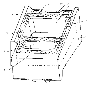
Figure 1 shows a perspective view of a throw
shoe with two pockets according to the invention.
Figure 2 shows a photograph. illustrating the
throw shoe with a single pocket according to the
invention.
Figure 3 shows a photograph of the throw shoe
with two pockets according to the invention.
Figures 4 and 5 show two photographs of a throw
shoe with two pockets according to the prior art,
illustratinq preferential points of wear.
Description of the various preferred embodiments of the
invention
Figure 1 illustrates diagramnlatically the throw
shoe, bearing the general reference 1, with two pockets
3 and 5 according to the invention, comprising the
composite reinforcement identified by the general
reference 6 and shown in hatched lines.
This composite is preferably made from an
agglomerate of ceramic particles based on
alumina-zirconia. These ceramic particles are
manufactured conventionally by electrofusion by
sintering, by thermal spraying or by any other process
allowing the two constituents to be fused together.
The structure of the composite reinforcement is
produced around the perimeter of the pockets of the
throw shoe at a minimum distance of 5 mm from the edges
of the pockets, thus preventing a. throw shoe from
wearing at the lower edge 9 and the upper edge 11, as
well as at the nose 13 and the exit 15 of the throw
shoe.
A complementary reinforcing structure 17 (also
shown in hatched lines) may be provided on the exit
face of the throw shoe 1.

CA 02322861 2000-09-05
6 -
As illustrated, the composite reinforcing
structure does not necessarily have to be placed over
the entire width, length or depth of the throw shoe in
order to prevent deterioration of the structure.
Figures 2 and 3 show two throw shoes of
different configurations, one having a single pocket
and the other having two pockets.
The geometry of the structure of the composite
is tailored to the geometrical configuration of the
throw shoe, this configuration being chosen depending
on the material to be crushed.
The particular configuration of the composite
structure as illustrated was chosen so as, on the one
hand, to limit wear of the entire piece of the thro-or
shoe and, on the other hand, to allow easy production
of the throw shoe provided in situ with the reinforcing
structure when the throw shoe is being cast.
The throw shoe therefore consists of a
heterogeneous element, but without attached pieces,
which has, in the regions predominantly exposed to
wear, a reinforcement integrated into the throw shoe in
the form of a structure based on a composite which is
formed from an iron-based alloy (steel or cast iron) on
the one hand and a ceramic having the property of wear
resistance for the envisaged uses, on the other.
Figures 4 and 5 show photographs of a throw
shoe with two pockets according to the prior art, in
which the preferential wear is essentially localized at
the nose of the throw shoe as well as at the lower edge
of the pockets in contact with the turntable.
Examole
A throw shoe with a composite reinforcement, as
shown in Figure 2, was compared with an identical throw
shoe without this composite rei:nforcement in an
application involving the crushing of rhyolite having
an incoming particle size of between 3 and 40 mm.

CA 02322861 2000-09-05
- 7 -
The lifetime of the throw shoe wit:h a composite
reinforcement is twice that obtained with equivalent
throw shoes without this reinforcement.

Representative Drawing
A single figure which represents the drawing illustrating the invention.
Administrative Status

2024-08-01:As part of the Next Generation Patents (NGP) transition, the Canadian Patents Database (CPD) now contains a more detailed Event History, which replicates the Event Log of our new back-office solution.

Please note that "Inactive:" events refers to events no longer in use in our new back-office solution.

For a clearer understanding of the status of the application/patent presented on this page, the site Disclaimer , as well as the definitions for Patent , Event History , Maintenance Fee  and Payment History  should be consulted.

Event History

Description Date
Time Limit for Reversal Expired 2015-03-16
Letter Sent 2014-03-17
Grant by Issuance 2008-05-27
Inactive: Cover page published 2008-05-26
Inactive: IPRP received 2008-01-08
Inactive: Final fee received 2007-12-27
Pre-grant 2007-12-27
Inactive: Adhoc Request Documented 2007-09-05
Letter Sent 2007-09-05
Notice of Allowance is Issued 2007-09-05
Inactive: Delete abandonment 2007-09-05
Inactive: Abandoned - No reply to Office letter 2007-06-11
Inactive: Received pages at allowance 2007-06-07
Inactive: Office letter 2007-03-09
Inactive: Approved for allowance (AFA) 2007-02-12
Amendment Received - Voluntary Amendment 2006-06-07
Letter Sent 2006-05-31
Reinstatement Requirements Deemed Compliant for All Abandonment Reasons 2006-05-09
Deemed Abandoned - Failure to Respond to Maintenance Fee Notice 2006-03-16
Inactive: S.30(2) Rules - Examiner requisition 2005-12-19
Letter Sent 2003-07-16
Request for Examination Received 2003-06-09
Request for Examination Requirements Determined Compliant 2003-06-09
All Requirements for Examination Determined Compliant 2003-06-09
Amendment Received - Voluntary Amendment 2003-06-09
Letter Sent 2001-01-05
Inactive: Cover page published 2000-12-06
Inactive: Single transfer 2000-12-01
Inactive: First IPC assigned 2000-11-29
Inactive: Courtesy letter - Evidence 2000-11-28
Inactive: Notice - National entry - No RFE 2000-11-23
Application Received - PCT 2000-11-17
Application Published (Open to Public Inspection) 1999-09-23

Abandonment History

Abandonment Date Reason Reinstatement Date
2006-03-16

Maintenance Fee

The last payment was received on 2008-02-27

Note : If the full payment has not been received on or before the date indicated, a further fee may be required which may be one of the following

  • the reinstatement fee;
  • the late payment fee; or
  • additional fee to reverse deemed expiry.

Please refer to the CIPO Patent Fees web page to see all current fee amounts.

Owners on Record

Note: Records showing the ownership history in alphabetical order.

Current Owners on Record
MAGOTTEAUX INTERNATIONAL S.A.
Past Owners on Record
CLAUDE PONCIN
Past Owners that do not appear in the "Owners on Record" listing will appear in other documentation within the application.
Documents

To view selected files, please enter reCAPTCHA code :


To view images, click a link in the Document Description column. To download the documents, select one or more checkboxes in the first column and then click the "Download Selected in PDF format (Zip Archive)" or the "Download Selected as Single PDF" button.

List of published and non-published patent-specific documents on the CPD .

If you have any difficulty accessing content, you can call the Client Service Centre at 1-866-997-1936 or send them an e-mail at CIPO Client Service Centre.


Document
Description 
Date
(yyyy-mm-dd) 
Number of pages   Size of Image (KB) 
Representative drawing 2000-12-06 1 10
Claims 2003-06-09 2 78
Cover Page 2000-12-06 1 42
Abstract 2000-09-05 1 64
Description 2000-09-05 7 266
Claims 2000-09-05 1 41
Claims 2006-06-07 2 75
Representative drawing 2007-06-12 1 15
Description 2007-06-07 7 268
Cover Page 2008-04-29 2 48
Reminder of maintenance fee due 2000-11-20 1 112
Notice of National Entry 2000-11-23 1 195
Courtesy - Certificate of registration (related document(s)) 2001-01-05 1 113
Acknowledgement of Request for Examination 2003-07-16 1 173
Courtesy - Abandonment Letter (Maintenance Fee) 2006-05-11 1 177
Notice of Reinstatement 2006-05-31 1 165
Commissioner's Notice - Application Found Allowable 2007-09-05 1 164
Maintenance Fee Notice 2014-04-28 1 170
Correspondence 2000-11-23 1 15
PCT 2000-09-05 12 374
Fees 2003-01-24 1 34
Fees 2002-01-21 1 32
Fees 2001-02-01 1 33
Fees 2004-02-26 1 34
Fees 2005-02-25 1 32
Fees 2006-05-09 2 56
Correspondence 2007-03-09 1 20
Fees 2007-03-15 1 42
Correspondence 2007-06-07 2 70
PCT 2000-09-06 9 306
Correspondence 2007-12-27 2 50
Fees 2008-02-27 1 42