Note: Descriptions are shown in the official language in which they were submitted.
CA 02322920 2000-10-06
EXHAUST PIPE ASSEMBLY OF TWO-PASSAGE CONSTRUCTION
BACKGROUND OF THE INVENTION
1. Field of the Invention
The present invention relates to an exhaust pipe
assembly which is suitable for connection between an
exhaust manifold of a multi-cylinder internal combustion
engine of a motor vehicle and a catalyst converter. In
particular, it relates to an exhaust pipe assembly
employing a two-passage construction in general in which a
so-called O pipe, whose exhaust passage is divided into
two by a partition plate, is used in order to prevent the
exhaust interference among the cylinders. It also relates
to an exhaust pipe assembly employing a double-pipe
construction in order to prevent the exhaust gas from
lowering in temperature before it reaches a catalytic
converter and to prevent personal harms due to high
temperature.
2. Description of Related Art
In order to prevent the exhaust interference among
the cylinders and to prevent the heat dissipation, an
exhaust pipe assembly of two-passage and double-pipe
construction is known, for example, from Published
Unexamined Japanese Patent Application No. 192727/1997.
This kind of conventional exhaust pipe assembly as shown
by reference alphabet E in FIG. l0A is connected to a
1
CA 02322920 2000-10-06
flange f2 of an exhaust manifold M of a multi-cylinder
internal combustion engine (not illustrated). The exhaust
pipe assembly E is made up of an inner pipe "a" and an
outer pipe b which are welded to a flange fl. A partition
plate c is elongated in a longitudinal direction of the
inner pipe "a" so as to form two exhaust passages gl, g2
divided along the diameter of the inner pipe "a." A
thermally insulating space a is provided between the
periphery (i.e., outer surface) of the inner pipe "a" and
the inner circumference of the outer pipe b. The
partition plate c is, in most cases, welded by laser beam
welding to an extended piece cl from an outside. A small
curvature R is formed at a base portion of that partition
plate c which comes into contact with the extended piece
cl to facilitate the deformation of the partition plate c.
The thermal expansion is thus absorbed by the extended
piece cl which is provided on each of the diametrically
opposite ends.
That portion of the partition plate c which lies on
the side of the flange fl is exposed most frequently to
the high-temperature exhaust gas as compared with a
portion of the inner pipe "a" and the flange fl, whereby a
maximum thermal expansion occurs therein. However, the
portion in question of the partition plate c is welded to
a slip-on or inserting hole of the flange fl together with
the inner pipe "a" and is therefore restricted in its
expansion in the diametrical direction. Therefore, the
2
CA 02322920 2000-10-06
partition plate c gives rise to buckling and deformation,
as shown by dotted lines in FIG. lOB, and the exhaust
passages gl, g2 are subject to changes in shape. As a
result, there is a possibility that the exhaust passages
in the exhaust pipe assembly E differ from those in the
exhaust manifold M. In addition, when the welded portions
in the extended pieces cl try to be displaced as a result
of the deformation in the partition plate c, the inner
pipe "a" cannot follow the deformation. The welded
portion thus sometimes gives rise to peeling, with the
resultant poor sealing effect. Further, as a result of
repeated bending loads due to thermal expansion and
contraction, the welded portion may give rise to fatigue
rupture and the partition plate c may be damaged due to
fatigue. In any of the above-described cases, the engine
output and the torque decrease.
In view of the above points, the present invention
has an object of providing an exhaust pipe assembly of
two-passage construction.
SLJNIMARY OF THE INVENTION
In order to attain the above and other objects,
according to one aspect of the present invention, there is
provided an exhaust pipe assembly of two-passage and
double-pipe construction, comprising: an inner pipe; a
partition plate meeting the inner pipe at both diametrical
meeting ends thereof so as to be elongated in a
3
CA 02322920 2000-10-06
longitudinal direction of the inner pipe, whereby two
passages divided across a diameter of the inner pipe are
formed; an outer pipe covering the inner pipe with a
thermally insulating space around a periphery of the inner
pipe, the outer pipe having on one longitudinal end
thereof a connecting portion for connection with a mating
member, wherein one end of the inner pipe is fixedly
connected to the outer pipe with a clearance between the
periphery of the inner pipe near each of the meeting ends
and an inner circumference of the outer pipe.
Preferably, the exhaust pipe assembly further
comprises a connecting member provided at the connecting
portion, for connecting the exhaust pipe assembly to the
mating member.
The inner pipe at the connecting portion is
preferably formed into a substantially true circle and the
outer pipe at the connecting portion is formed into an
ellipse having a larger diameter in a direction of the
partition plate, whereby the clearance is formed between
the inner pipe and the outer pipe. Alternatively, the
inner pipe at the connecting portion may be formed into an
ellipse having a smaller diameter in the direction of the
partition plate and the outer pipe at the connecting
portion may be formed into a substantially true circle so
that the clearance is formed between the inner pipe and
the outer pipe.
Further, preferably the inner pipe and the partition
4
CA 02322920 2000-10-06
plate are formed by a single plate material which is bent
substantially into a configuration of an alphabet "S" or
of a cocoon in cross section.
According to the above-described arrangement,
although the partition plate is thermally extended in an
amount larger than that of the inner pipe to thereby urge
the inner pipe radially outward, the thermal expansion
takes place inside the clearance. Therefore, the
resistance of the inner pipe against the deformation due
to the thermal expansion of the partition plate is smaller
and the thermal stress is thus small.
According to another aspect of the present
invention, there is provided an exhaust pipe assembly of
two-passage and double-pipe construction, comprising: an
inner pipe; a partition plate meeting the inner pipe at
both diametrical meeting ends thereof so as to be
elongated in a longitudinal direction of the inner pipe,
whereby two passages divided across a diameter of the
inner pipe are formed; an outer pipe covering the inner
pipe with a thermally insulating space around a periphery
of the inner pipe, wherein the outer pipe has on one
longitudinal end thereof a connecting portion for
connection with a mating member, and wherein the outer
pipe is fixed to the periphery of the inner pipe at a
short distance toward a downstream side from the
connecting portion while leaving a clearance at the
connecting portion between the inner pipe and the outer
5
CA 02322920 2000-10-06
pipe.
Preferably, the holding portion is formed by
reducing a diameter of the outer pipe into close contact
with the periphery of the inner pipe. The exhaust pipe
preferably further comprises a connecting member provided
at the connecting portion which is for connecting the
exhaust pipe to the mating member. The inner pipe and the
outer pipe at the connecting portion may be formed
concentric with each other. Still furthermore, the inner
pipe and the partition plate may be formed by a single
plate material which is bent substantially into a
configuration of an alphabet "S."
According to the above arrangement, the partition
plate can be thermally extended into the clearance between
the inner pipe and the outer pipe. Further, since the
inner pipe and the outer pipe are formed into concentric
with each other, the machining is relatively easy.
According to still another aspect of the present
invention, there is provided an exhaust pipe assembly of
two-passage construction, comprising: an exhaust pipe; a
partition plate meeting the exhaust pipe at both
diametrical meeting ends thereof so as to be elongated in
a longitudinal direction of the exhaust pipe, whereby two
passages divided across a diameter of the exhaust pipe are
formed; a cover member surrounding a periphery of one
longitudinal end of the exhaust pipe, wherein the cover
member is fixedly connected to the exhaust pipe at one end
6
CA 02322920 2000-10-06
of the cover member with a clearance between the periphery
of the exhaust pipe and an inner circumference of the
cover member, the other end of the cover member and said
one longitudinal end of the exhaust pipe forming a
connecting portion for connection with a mating member.
Preferably, the cover member is fixedly connected to
the exhaust pipe at that end of the cover member which is
on a downstream end of the exhaust pipe.
The exhaust pipe assembly preferably further
comprise a connecting member provided at the connecting
portion which is for connecting the exhaust pipe assembly
to the mating member.
Still furthermore, the inner pipe and the partition
plate may be formed by a single plate material which is
bent substantially into a configuratian of an alphabet
S.
According to this arrangement, the exhaust pipe of
two-passage construction can be connected to the mating
member by means of the cover member while allowing for the
thermal expansion of the inner pipe and the partition
plate into the clearance between the inner pipe and the
outer pipe.
HRIEF DESCRIPTION OF THE DRAWINGS
The above and other objects and the attendant
advantages of the present invention will become readily
apparent by reference to the following detailed
7
CA 02322920 2000-10-06
description when considered in conjunction with the
accompanying drawings wherein:
FIG. 1 is a longitudinal sectional view of an
exhaust pipe assembly of two-passage and dual-pipe
construction according to one example of the present
invention;
FIG. 2 is an end view of FIG. 1;
FIG. 3 is an enlarged view of portion "A" in FIG. 2;
FIG. 4 is an end view of a modified example of the
present invention;
FIG. 5 is an end view of another modified example of
the present invention;
FIG. 6 is a longitudinal sectional view of an
exhaust pipe assembly of two-passage and dual-pipe
construction according to another example of an. exhaust
pipe assembly of two-passage and dual-pipe construction;
FIG. 7A is a sectional view of the example of FIG. 6
as seen in a direction of an arrow "a" - "a" in FIG. 6,
and FIG. 7H is a sectional view thereof as seen in a
direction of an arrow "b" - "b" in FIG. 6;
FIG. 7C is a modified example of the present
invention as seen in a direction of an arrow "a" - "a" in
FIG. 6, and FIG. 7D is a sectional view as seen in a
direction of an arrow "b" - "b" in FIG. 6;
FIG. 8 is a longitudinal sectional view of an
exhaust pipe assembly of two-passage construction
according to another example of the present invention;
8
CA 02322920 2000-10-06
FIG. 9A is a sectional view of the example of FIG. 8
as seen in a direction of an arrow "a" - "a" in FIG. 8,
and FIG. 9B is a sectional view thereaf as seen in a
direction of an arrow "b" - "b" in FIG. 8:
FIG. 9C is a sectional view of another modified
example of the present invention as seen in a direction of
an arrow "a" - "a" in FIG. 8, and FIG. 9D is a sectional
view as seen in a direction of "b" - "b" in FIG. 8;
FIG. l0A is a front view of a conventional exhaust
pipe assembly of two-passage and double-pipe construction,
and FIG. lOB is a sectional view as seen in a direction of
"b" - "b" in FIG. 8A.
DETAILED DESCRIPTION OF PREFERRED EMBODIMENTS
A detailed explanation will now be made about
preferred embodiments of the present invention with
reference to the accompanying drawings.
FIGS. 1 through 3 show one example of the present
invention in which the exhaust pipe assembly is of a two-
passage and double-pipe construction.
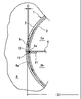
In FIG. 1, reference numeral 1 denotes a pipe main
body of an exhaust pipe assembly of two-passage and
double-pipe construction for use iri an exhaust-gas system
for an internal combustion engine of a motor vehicle.
Reference numeral 2 denotes an inner pipe. Reference
numeral 3 denotes an outer pipe which is disposed on a
periphery (i.e., outer circumference) of the inner pipe 2.
9
CA 02322920 2000-10-06
Reference numeral 4 denotes a partition plate which
extends in a diametrical direction of the inner pipe 2 so
as to meet the inner pipe 2 at the diametrically opposite
meeting ends 4a, 4a (see FIG. 3). The partition plate 4
is thus disposed inside the inner pipe 2 such that the
inner pipe 2 is divided along a longitudinal direction of
the inner pipe 2. The inner pipe 2 is therefore divided
along the diameter of the inner pipe 2 into two passages
2a, 2b for passing exhaust gas therethrough. On a left
end (as seen in FIG. 1) of the pipe main body 1, the outer
pipe 3 is reduced in diameter so that the outer pipe 3
substantially comes into close contact with the periphery
of the inner pipe 2. A connecting portion 5 of a smaller
diameter is thus formed. A flange 6, which is also
defined as a connecting member, is then fitted or slipped
onto the periphery of this connecting portion 5 and is
welded together. The flange 6 is then connected to a
collecting pipe portion of an exhaust manifold through a
mating member such as a mating flange (not illustrated).
Near a right end portion (as seen in FIG. 1) of the pipe
main body l, inward projections 7, 8 are partially formed
on the inner circumference of the outer pipe 3. A spacer
9 made of a wire mesh is filled into a space between the
periphery of the inner pipe 2 and the inner circumference
of the outer pipe 3 within a range between the projections
7, 8. A thermally insulating space 10 is thus formed
between the spacer 9 and the connecting portion 5 on the
CA 02322920 2000-10-06
r
left end of the pipe main body 1.
In the above-described example, the connecting
portion 5 is connected to the mating member through a pair
of flanges (one of the pair is not illustrated). However,
the connecting portion 5 may be directly connected to the
mating member which is in the form of an exhaust manifold
of the engine, without using flanges at all.
As can be seen from FIGS. 2 and 3, the inner pipe 2
and the partition plate-4 are made of a single piece of
plate material. The plate material is bent into a
configuration which looks substantially like an alphabet
"S" in its cross section. In other words, starting from
one circumferential end (as seen in FIG. 2), an upper
semicircular section, a horizontal plate section, and a
lower semicircular section are formed in a continuous
manner. At both starting end and finishing end of the "S"
configuration, there are formed slightly bent extended
pieces 11, 11. These extended pieces 11, 11 are arranged
to be in close contact with respective flat end portions
(i.e., at diametrically opposite ends) of the horizontal
plate section of the partition plate 4. In this manner, a
meeting end 4a is formed on each of the diametrical ends
of the partition plate 4. The "meeting end" is used in a
sense that the partition plate 4 and the circumferential
portion of the inner pipe 2 meet together. The meeting
end (or a base end portion) 4a of the partition plate 4,
on each diametrical end thereof, is combined by welding at
11
CA 02322920 2000-10-06
a welded portion 12. In this manner, the inner pipe 2 of
true circle and the partition plate 4 of a flat shape are
formed.
On the other hand, the outer pipe 3 at the
connecting portion 5 is reduced in diameter as described
hereinabove, and is further formed into an ellipse which
has a larger diameter D1 in the direction of the partition
plate 4 (i.e., in the direction in which the partition
plate 4 diametrically extends) and a smaller diameter D2
in the direction perpendicular to the diameter D1. When
the connecting portion 5 is fitted into the inner pipe 2,
a clearance 13 occurs between the periphery (or the outer
surface) of the inner pipe 2 and the inner circumference
of the outer pipe 3 near each of the meeting ends 4a of
the partition plate 4 and the inner pipe 2. In the
remaining range of the connecting portion 5, however, the
inner pipe 2 and the outer pipe 3 are brought into close
contact with each other and are welded at two welded
portions 14 on each of the short-diameter portions. The
maximum size of the clearance C is set to a value which
takes into consideration the thermal expansion. For
example, when the inner diameter of the inner pipe 2 is 66
mm, the clearance C is set to a range of 0.55 mm through
0.75 mm. The connecting portion 5 is fitted into the
true-circle inserting hole 6a of the flange 6 and welded
together, but the outer pipe 3 is maintained in the
elliptic shape and is welded as it is to the flange 6.
12
CA 02322920 2000-10-06
r
The clearance between the periphery of the short-diameter
portion of the outer pipe 3 and the inserting hole 6a of
the flange 6 is filled by welding seams. However, the
clearance 13 remains as it is on each of the diametrical
ends so as to facilitate the thermal expansion of the
partition plate 4. This clearance 13 is extremely small
in size and, therefore, the exhaust gas flowing into this
clearance goes out into a catalytic converter (not
illustrated).
When an engine of the motor vehicle is started, the
exhaust gas alternately flows into the exhaust passages
2a, 2b. As a result, the semicircular cylindrical
surfaces in the inner pipe 2 are intermittently heated.
The partition plate 4, on the other hand, is alternately
heated by the exhaust gas to pass along both surfaces of
the partition plate 4 to thereby attain the highest
temperature. The partition plate 4 thus thermally expands
in the widthwise (i.e., diametrical) direction in a
magnitude which is larger than those of the inner pipe 2
and the outer pipe 3. As a result, the inner pipe 2 near
the meeting ends 4a is forcibly bent outward. However,
since the bending takes place only in the clearance 13,
the resistance against the thermal expansion of the
partition plate 4 is small, and a stress which occurs in
the partition plate 4 or in the meeting ends 4a is small.
In this manner, there is no possibility of occurrence of
damages due to buckling, deformation, peeling; or the like.
13
CA 02322920 2000-10-06
In a modified example in FIG. 4, the outer pipe 3 is
formed into a true circle and the inner pipe 2 is formed
into an ellipse in which the diameter dl in the direction
in which the partition plate 4 extends is smaller than the
diameter d2 in the direction which is perpendicular to dl.
A clearance 13 is thus formed on an extended line of the
partition plate 4, and has the same effect as in the
example shown in FIGS. 1 through 3. The partition plate 4
in this example is not the same as that in FIGS. 2 and 3.
Namely, it is not formed by bending a single plate.
In another modified example shown in FIG. 5, the
neighborhood of the meeting end 4a of the partition plate
4 of the inner pipe 2 is formed into a flat plane so that
the inner pipe 2 as a whole looks substantially like, in
cross section, an oval or a shape like a cocoon. The
effects thereof are substantially the same as those of the
above-described examples.
As still another modified example, though not
illustrated, the shape of the outer pipe 3 may be formed
as follows instead of the elliptic shape in FIGS. 1
through 3. Namely, the neighborhood of the large-diameter
portion of the illustrated ellipse is formed into a
stepped shape made up of a smaller circular portion and a
circular portion which is slightly larger in diameter than
the smaller circular portion. The clearance 13 can thus
be formed by the space formed in the stepped portion.
As a further modified example of the above described
14
CA 02322920 2000-10-06
invention of two-passage and double-pipe construction,
there can be employed the following arrangement as shown
in FIG. 6 and FIGS. 7A through 7D. Namely, reference
numeral 101 denotes a pipe main body of an exhaust pipe
assembly of two-passage and double-pipe construction.
Reference numeral 102 denotes an inner pipe. Reference
numeral 103 denotes an outer pipe which is disposed on a
periphery of the inner pipe 102. Reference numeral 104
denotes a partition plate which extends in the diametrical
direction of the inner pipe 102 so as to meet the inner
pipe 102 at the diametrically opposite meeting ends 104a,
104a. The partition plate 104 is thus disposed inside the
inner pipe 102 such that the inner pipe 102 is divided
along a longitudinal direction of the inner pipe 102. The
inner pipe 102 is thus divided along the diameter of the
inner pipe into two passages 102a, 102b for passing
exhaust gas therethrough. The outer pipe 103 has a ring-
shaped reduced-diameter portion 107 in which the inner
circumference of the outer pipe 103 comes into close
contact with the periphery of the inner pipe 102 as shown
in FIG. 7B for further fixing them together, e.g., by
means of welding or the like. This reduced-diameter
portion 107 thus serves as a fixedly holding portion 115
to hold the inner pipe 102 and the outer pipe 103
together. The inner pipe 102 and the outer pipe 103 are
disposed in a concentric relationship with each other.
Therefore, the upstream portion of this reduced diameter
CA 02322920 2000-10-06
portion 107 forms a clearance 113 between the periphery of
the inner pipe 102 and the inner circumference of the
outer pipe 103. The outer pipe 103 on the upstream end at
the connecting portion 105 is connected to a flange 106
which is for further connection to a mating member such as
a mating flange (not illustrated) on the side of the an
exhaust manifold. The upstream end of the inner pipe 102
is left free from connection to the flange 106. This
holding portion 115 may be formed on a downstream side of
the connecting portion 105 at a short distance therefrom.
This distance may be conveniently determined on a case by
case basis so as to secure the connection to the flange
106 or the like.
The above-described clearance 113 serves to receive
therein the thermally extended inner pipe 102, especially
at those diametrical ends of the partition plate 104 which
are subject to larger thermal expansions.
The partition plate 104 may be formed either into an
integral construction as shown in FIGS. 7A and 7B, or into
he configuration of an alphabet "S" or of a cocoon in
cross section as shown in FIGS. 7C and 7D.
An explanation has so far been made about the
examples in which the exhaust pipe assembly has a double-
pipe construction. The present invention is not limited
to the double-pipe construction, but can also be applied
to a single-pipe construction as described hereinbelow
with reference to FIGS. 8 and 9A through 9D.
16
CA 02322920 2000-10-06
An exhaust pipe assembly in FIG. 8 has an exhaust
pipe 210. Inside this exhaust pipe 210, there is disposed
a partition plate 204 which meets the exhaust pipe 210 at
both diametrical meeting ends 204a, 204a of the partition
plate 204 so as to be elongated in a longitudinal
direction of the exhaust pipe 210. The exhaust pipe 210
is thus divided into two passages 210a, 210b across the
diameter of the exhaust pipe 210. This arrangement is
substantially the same as that of the inner pipe and the
partition plate in the above-described double-pipe
construction.
On an upstream end (left end in FIG. 8), there is
provided a cover member 211 which covers the periphery of
the upstream end of the exhaust pipe 210 with a clearance
213 therebetween. The downstream end of the cover member
211 is reduced in diameter so as to come into close
contact with the periphery of the exhaust pipe 210, and is
fixed thereto by means of welding or the like. In this
manner, a connecting portion 205 for connection to a
flange 206 is formed.
The upstream end of the exhaust pipe 210 is left
free and the upstream end of the cover member 211 is
connected to a flange 206, which is also called a
connecting member, by welding the periphery of the cover
member 211 to the flange 206. In this manner, the
clearance 213 is formed between the periphery of the
exhaust pipe 210 and the inner circumference of the cover
17
CA 02322920 2000-10-06
member 211 as shown in FIG. 9A. The downstream end of the
cover member 211 is fixed to the periphery of the exhaust
pipe 210 as explained above and as shown in FIGS. 8 and
9B. The high-temperature exhaust gas flows through the
exhaust pipe 210 in a manner similar to that in the
examples given hereinabove. On the upstream end of the
exhaust pipe 210, the partition plate 204 is free to
expand in the diametrical direction within the clearance
213. On the other hand, the downstream end of the cover
member 212 is fixedly connected to the periphery of the
exhaust pipe 210 around the entire circumference as shown
in FIG. 9B. Therefore, at this particular portion, the
partition plate 204 is restricted in its thermal expansion
in the diametrical direction. As a result, the partition
plate gives rise to a deformation 104b as shown by dotted
lines in FIG. 9B. However, since the thermal expansion at
this restricted portion is smaller as compared with that
at the upstream endmost portion, the adverse effects on
the distribution of the exhaust gas is relatively limited.
FIGS. 9C and 9D show another example of the
partition plate 204 which is a modification of that in
FIGS. 9A and 9B. In this example, the partition plate 204
is formed by a single plate like in the example shown in
FIGS. 2 and 3. Therefore, detailed explanations thereof
are omitted.
As can be seen from the above-described
explanations, according to the present invention, due to
18
CA 02322920 2000-10-06
the presence of the clearance, the thermal expansion of
the partition plate is not disturbed.
It is readily apparent that the above-described
exhaust pipe assembly of two-passage construction meets
all of the objects mentioned above and also has the
advantage of wide commercial utility. It should be
understood that the specific form of the invention
hereinabove described is intended to be representative
only, as certain modifications within the scope of these
teachings will be apparent to those skilled in the art.
Accordingly, reference should be made to the
following claims in determining the full scope of the
invention.
19