Note: Descriptions are shown in the official language in which they were submitted.
CA 02322924 2000-10-10
GAS TURBINE EQUIPMENT AND TURBINE BLADE
BACKGROUND OF THE INVENTION
1. Field of the Invention
The present invention relates to a turbine blade of a gas
turbine or the like and a gas turbine equipment using this turbine
blade.
2. Description of the Prior Art
Fig. 5 is a schematic explanatory view of a structure of a
turbine portion and a cooling air system for cooling this turbine
portion in a gas turbine equipment in the prior art.
The turbine portion comprises a rotational portion of a rotor 1
and a turbine moving blade 2 and a stationary portion 5 of a casing
3, a turbine stationary blade 4, various supporting members and the
1 ike.
In the turbine portion, a high temperature high pressure
combustion gas supplied from a combustor 6 is converted into a high
velocity flow by the turbine stationary blade 4 to rotate the
turbine moving blade 2 for generation of power.
Construction members of the rotational portion and the
stationary portion which are adjacent to the combustion gas need to
be cooled so that their temperature due to heat input from the
combustion gas may not exceed their respective allowable
temperature and, for cooling of the rotational portion having the
rotor 1 and the turbine moving blade 2, it is usual that cooling
medium 7 is supplied as shown by arrows in Fig. 5.
The cooling medium 7 is often a bleed air or discharge air
-1-
CA 02322924 2000-10-10
,"..
taken from a compressor (not shown) or sometimes the bleed air or
discharge air once supplied into a cooler (not shown) and cooled to
an appropriate temperature.
Further, as the cooling medium to cool the mentioned portions,
there is recently a case where steam from an outside system is
applied in place of the bleed air or discharge air from the
compressor, but herebelow description will be made based on the
cooling air system which is generally employed as a typical
examp 1 e.
While the cooling medium 7 flowing in the rotational portion
takes a route to flow through an interior of the rotor 1 to enter an
interior of the turbine moving blade 2 for cooling thereof and then
to join into a combustion gas path, in the case of using steam as
the cooling medium as mentioned above, the cooling medium which has
been heat-exchanged by cooling the turbine moving blade 2 and the
like is recovered so that thermal energy thereof may be made use of
in an outside system and thermal efficiency of the plant may be
enhanced.
In the gas turbine equipment having the mentioned basic
structure, description will be made concretely on the prior art
turbine portion thereof with reference to Figs. 6 to 10.
Fig. 6 is a longitudinal cross sectional view showing a main
structure of a prior art turbine moving blade, Fig. 7 is a
perspective view showing a main structure of a prior art turbine
stationary blade, Fig. 8 is an enlarged view of a part of the
turbine stationary blade of Fig. 7, Fig. 9 is a qualitative
explanatory view showing a metal temperature behavior due to
-2-
' CA 02322924 2000-10-10
thickness difference between thickness of a turbine moving blade
trailing edge portion and that of a platform in the prior art, and
Fig. 10 is likewise a qualitative explanatory view showing a metal
temperature behavior due to thickness difference between thickness
of a turbine stationary blade trailing edge portion and that of a
shroud in the prior art.
In a leading edge portion of the turbine moving blade 2 which
is exposed to an especially high temperature combustion gas, in
order to stand a high thermal load, it is usual to provide a
cooling passage 8 through which the cooling medium 7 is supplied for
effecting a convection cooling in the turbine moving blade 2.
Cooling passage in the moving blade is often constructed to
repeat several turnings so as to form a serpentine passage on
design demand, wherein the passage turns at a turning portion 11
provided in the vicinity of a tip portion 9 of the turbine moving
blade 2 and a joint portion 10 of the turbine moving blade 2.
Thus, the cooling medium 7 flows through the cooling passages
to cool the interior of the turbine moving blade 2. However, in
case the turbine moving blade 2 is one which receives higher thermal
load, there is provided a film cooling hole 12 in a blade surface
of the turbine moving blade 2 and a portion of the cooling medium 7
is blown therethrough onto the blade surface on the combustion gas
path side so that the blade surface may be covered by a low
temperature air curtain and thereby a film cooling for reducing the
thermal load from the blade surface as well can be effected.
On the other hand, a trailing edge portion 14 of the turbine
moving blade 2 is usually designed to be relatively thin in order to
-3-
' CA 02322924 2000-10-10
reduce an aerodynamic loss of the combustion gas and, for this
purpose, if the turbine moving blade 2 is to be cooled, a pin fin
cooling or a slot cooling by way of many slots is employed for
cooling the interior of the blade, or the film cooling by way of
blowing air from a ventral side surface of the blade through the
film cooling hole is effected.
In case of the turbine stationary blade 16, in order to form a
gas flow path, structure of the blade is made such that an inner end
of a blade profile portion 17 is inserted into an inner shroud 18
and an outer end of the blade profile portion 17 is inserted into
an outer shroud 19, and while this set of one inner shroud 18 and
one outer shroud 19 is usually provided for each of the turbine
stationary blades 16, there is also such a case where the set of
one inner shroud 18 and one outer shroud 19 is provided so as to
cover a plurality of the turbine stationary blades 16.
The turbine stationary blade 16 is usually formed by precision
casting and is then worked by machining, wherein the inner shroud
18, the outer shroud 19 and the blade profile portion 17 are
generally formed integrally by casting.
As mentioned above, the platform 15 supporting the turbine
moving blade 2 forms a part of the gas flow path in an axial flow
turbine and is made relatively thicker as compared with the trailing
edge portion 14 of the blade so as to stand centrifugal force or
the like.
For this reason, in operation~of the gas turbine including
start and stop, load change or the like, there may arise an
excessively large temperature difference between the platform 15 and
- 4 -
' CA 02322924 2000-10-10
the blade trailing edge portion 14, by which thermal stress is
liable to occur at a transition time or in a steady operation time
so that there is a risk to cause cracks and if the cracks occur,
there is a problem to damage a reliability of the turbine moving
blade.
Also, in the turbine stationary blade 16, in order to reduce an
aerodynamic loss, a trailing edge portion 20 of the blade is
designed as thin as possible and, on the other hand, the inner
shroud 18 and the outer shroud 19 are usually designed relatively
thicker for holding the strength. Thus, like the turbine moving
blade 2, there is a problem that cracks are considered to occur by
the thermal stress following a start and stop of the gas turbine or
the like, which results in damaging the reliability.
The mentioned relation between the moving blade trailing edge
portion and the platform is shown in Fig. 9 qualitatively as a
metal temperature behavior which is caused by a thickness difference
between thickness of the moving blade trailing edge portion and
that of the platform. Likewise, the mentioned relation between the
stationary blade trailing edge portion and the shroud is shown in
Fig. 10 qualitatively as a metal temperature behavior which is
caused by a thickness difference between thickness of the stationary
blade trailing edge portion and that of the shroud.
In Figs, 9 and 10, the vertical axis means a gas turbine
rotational speed and metal temperature and the horizontal axis means
a lapse of time. When the gas turbine is stopped, gas turbine
rotational speed C~, CZ is reduced. In the area of C~ and C2, the
blade trailing edge portion which is of a smaller thermal capacity
-5-
' CA 02322924 2000-10-10
,w,.,
is cooled quicker and moving blade trailing edge portion metal
temperature B1 and stationary blade trailing edge portion metal
temperature BZ are reduced largely. On the contrary, the platform
and the shroud are of a larger thermal capacity, respectively, and
platform metal temperature A~ and shroud metal temperature AZ are
reduced comparatively slowly. Hence, temperature differencep t
between both portions becomes larger and a problem of occurrence of
thermal stress arises there.
SUMMARY OF THE INVENTION
Thus, in order to solve the problem in the prior art, it is an
object of the present invention to provide highly reliable moving
blade and stationary blade which are able to suppress an occurrence
of thermal stress caused by the mentioned temperature difference as
well as to provide a gas turbine equipment comprising these moving
blade and stationary blade.
In order to solve the mentioned problem in the prior art, the
present invention provides the following first means:
A gas turbine equipment comprising a rotational portion of a
rotor and a moving blade, a stationary portion of a casing, a
stationary blade, various supporting members and the like and a
combustor, characterized in that there is provided a thermal stress
reducing portion in any one or both of a moving blade joint adjacent
portion between a moving blade trailing edge portion and a platform
and a stationary blade joint adjacent portion between a stationary
blade trailing edge portion and a shroud.
According to the mentioned first means, the thermal stress
-6-
' CA 02322924 2000-10-10
reducing portion is provided in any one or both of the moving blade
joint adjacent portion between the moving blade trailing edge
portion and the platform and the stationary blade joint adjacent
portion between the stationary blade trailing edge portion and the
shroud, and thereby the undesirable thermal stress is reduced in
these joint adjacent portions and the reliability of the gas
turbine equipment can be enhanced.
Also, the present invention provides the following second
means:
A gas turbine equipment as mentioned in the first means,
characterized in that the thermal stress reducing portion provided
in the moving blade joint adjacent portion is formed such that the
platform in the moving blade joint adjacent portion is partially cut
away and a remaining thickness of the platform so cut away is
approximately same as a thickness of the moving blade trailing edge
portion.
According to the mentioned second means, the thermal stress
reducing portion is formed in such a structure that the platform in
the moving blade joint adjacent portion between the moving blade
trailing edge portion and the platform is partially cut away and a
remaining thickness of the platform so cut away is approximately
same as a thickness of the moving blade trailing edge portion, and
thereby the undesirable thermal stress is surely reduced by the
simply workable means and the reliability of the gas turbine
equipment can be enhanced.
Also, the present invention provides the following third means:
A gas turbine equipment as mentioned in the first means,
_7_
' CA 02322924 2000-10-10
characterized in that the thermal stress reducing portion provided
in the stationary blade joint adjacent portion is formed such that
the shroud in the stationary blade joint adjacent portion is thinned
and a remaining thickness of the shroud so thinned is approximately
same as a thickness of the stationary blade trailing edge portion.
According to the mentioned third means, the thermal stress
reducing portion is formed in such a structure that the shroud in
the stationary blade joint adjacent portion between the stationary
blade trailing edge portion and the shroud is thinned and a
remaining thickness of the shroud so thinned is approximately same
as a thickness of the stationary blade trailing edge portion, and
thereby the undesirable thermal stress is surely reduced by the
simply workable means and the reliability of the gas turbine
equipment can be enhanced.
Also, the present invention provides the following fourth
means:
A turbine blade comprising a moving blade joint adjacent
portion between a moving blade trailing edge portion and a platform,
characterized in that the platform in the moving blade joint
adjacent portion is partially cut away and a remaining thickness of
the platform so cut away is approximately same as a thickness of the
moving blade trailing edge portion.
According to the mentioned fourth means, the structure is
employed such that the platform in the moving blade joint adjacent
portion between the moving blade trailing edge portion and the
platform is partially cut away and a remaining thickness of the
platform so cut away is approximately same as a thickness of the
_ g _
CA 02322924 2000-10-10
,",..u
moving blade trailing edge portion, and thereby the undesirable
thermal stress occurring in the moving blade joint adjacent portion
is reduced and the reliability of the turbine blade can be enhanced.
Also, the present invention provides the following fifth means:
A turbine blade comprising stationary blade inner and outer
joint adjacent portions between a stationary blade trailing edge
portion and an inner shroud and between said stationary blade
trailing edge portion and an outer shroud, respectively,
characterized in that each of the inner shroud in the stationary
blade inner joint adjacent portion and the outer shroud in the
stationary blade outer joint adjacent portion is thinned and a
remaining thickness each of the inner shroud and the outer shroud so
thinned is approximately same as a thickness of the stationary
blade trailing edge portion.
According to the mentioned fifth means, the structure is
employed such that each of the inner shroud in the stationary blade
inner joint adjacent portion between the stationary blade trailing
edge portion and the inner shroud and the outer shroud in the
stationary blade outer joint adjacent portion between the
stationary blade trailing edge portion and the outer shroud is
thinned and a remaining thickness each of the inner shroud and the
outer shroud so thinned is approximately same as a thickness of the
stationary blade trailing edge portion, and thereby the undesirable
thermal stress occurring in the stationary blade inner and outer
joint adjacent portions is reduced and the reliability of the
turbine blade can be enhanced.
Further, the present invention provides the following sixth
_g_
CA 02322924 2004-04-27
means:
A gas turbine equipment comprising the turbine blade
mentioned in the fourth means and that mentioned in the fifth
means.
According to the mentioned sixth means, the structure is
employed such that, on the moving blade side, the platform in the
moving blade joint adjacent portion between the moving blade
trailing edge portion and the platform is partially cut away and, on
the stationary blade side, each of the inner shroud in the
stationary blade inner joint adjacent portion between the
stationary blade trailing edge portion and the inner shroud and the
outer shroud in the stationary blade outer joint adjacent portion
between the stationary blade trailing edge portion and the outer
shroud is thinned, and thereby the undesirable thermal stress
occurring both on the moving blade side and on the stationary side
is reduced and the reliability of the gas turbine equipment can be
enhanced.
In another aspect, the present invention provides a turbine
blade comprising a moving blade joint adjacent portion between a
moving blade trailing edge portion and a platform, wherein said
platform in said moving blade joint adjacent portion is partially cut
away and a remaining thickness of said platform so cut away is
approximately the same as a thickness of said moving blade
trailing edge portion.
In another aspect, the present invention provides a turbine
blade comprising stationary blade inner and outer joint adjacent
portions between a stationary blade trailing edge portion and an
inner shroud and between said stationary blade trailing edge
portion and an outer shroud, respectively, wherein each of said
inner shroud in said stationary blade inner joint adjacent portion
- 1~ -
CA 02322924 2004-04-27
and said outer shroud in said stationary blade outer joint adjacent
portion is thinned and a remaining thickness each of said inner
shroud and said outer shroud so thinned is approximately the
same as a thickness of said stationary blade trailing to edge
portion.
In another aspect, the present invention provides gas turbine
equipment comprising a moving turbine blade and a stationary
turbine blade, wherein said moving turbine blade comprises a
moving blade joint adjacent portion between a moving blade
l0 trailing edge portion and a platform, wherein said platform in said
moving blade j oint adj acent portion is partially cut away and a
remaining thickness of said platform so cut away is approximately
the same as a thickness of said moving blade trailing edge portion,
and wherein said stationary turbine blade comprises a turbine
blade comprising stationary blade inner and outer joint adjacent
portions between a stationary blade trailing edge portion and an
inner shroud and between said stationary blade trailing edge
portion and an outer shroud, respectively, wherein each of said
inner shroud in said stationary blade inner joint adjacent portion
and said outer shroud in said stationary blade outer joint adjacent
portion is thinned and a remaining thickness each of said inner
shroud and said outer shroud so thinned is approximately the
same as a thickness of said stationary blade trailing to edge
portion.
In yet another aspect, the present invention provides a
turbine blade comprising at least one blade joint adjacent portion
between a blade trailing edge portion and a platform or inner or
outer shroud, wherein said platform or inner or outer shroud, in
said at least one joint adjacent portion, is thinner than other
portions of said platform or inner or outer shroud such that a
- 10a -
,. ~ CA 02322924 2004-04-27
thickness of said platform or inner or outer shroud at said joint
adjacent portion is approximately the same as a thickness of said
blade trailing edge portion.
More preferably, said turbine blade is a moving blade, said
blade trailing edge portion is a moving blade trailing edge portion,
and said at least one j oint adj acent portion is a moving blade j oint
adjacent portion between said moving blade trailing edge portion
and said platform.
More preferably, said turbine blade is a stationary blade, said
blade trailing edge portion is a stationary blade trailing edge
portion, and said at least one joint adjacent portion comprises
stationary blade inner and outer joint adjacent portions between
said stationary blade trailing edge portion and said inner shroud
and between said stationary blade trailing edge portion and said
outer shroud.
BRIEF DESCRIPTION OF THE DRAWINGS
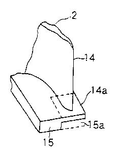
Figs. 1 (a) and 1 (b) show an outline of a turbine moving blade
of a first embodiment according to the present invention and Fig.
1 (a) is a side view of the turbine moving blade including portion A
which is a thinned portion of a platform adjacent to a trailing edge
portion of the turbine moving blade and Fig. 1(b) is an enlarged
perspective view showing the portion A of Fag. 1 (a) .
Fig. 2 is an explanatory view showing a temperature
difference between metal temperature of the moving blade trailing
edge portion and that of the platform.
- lOb -
' CA 02322924 2000-10-10
Fig. 3 is an enlarged side view showing a thinned portion of a
shroud adjacent to a turbine stationary blade of a second embodiment
according to the present invention.
Fig. 4 is an explanatory view showing a temperature difference
between metal temperature of a stationary blade trailing edge
portion and that of the shroud of the turbine stationary blade of
Fig. 3.
Fig. 5 is a schematic explanatory view of a structure of a
turbine portion and a cooling air system for cooling this turbine
portion in a gas turbine equipment in the prior art.
Fig. 6 is a longitudinal cross sectional view showing a main
structure of a prior art turbine moving blade.
Fig. 7 is a perspective view showing a main structure of a
prior art turbine stationary blade.
Fig. 8 is an enlarged view of a part of the turbine stationary
blade of Fig. 7.
Fig. 9 is a qualitative explanatory view showing a metal
temperature behavior due to a thickness difference between thickness
of a turbine moving blade trailing edge portion and that of a
platform in the prior art.
Fig. 10 is a qualitative explanatory view showing a metal
temperature behavior due to a thickness difference between
thickness of a turbine stationary blade trailing edge portion and
that of a shroud in the prior art.
DESCRIPTION OF THE PREFERRED EMBODIMENTS
A first embodiment according to the present invention will be
- 1 1 -
CA 02322924 2004-04-27
described with reference to Figs. 1 (a), 1 (b) and 2.
Figs. 1 (a) and 1 (b) show an outline of a turbine moving blade
of the first embodiment according to the present invention, and
Fig. 1 (a) is a side view of the turbine moving blade including
portion A which is a thinned portion of a platform adjacent to a
trailing edge portion of the turbine moving 'blade and Fig. 1 (b) is an
enlarged perspective view showing the portion A of Fig. 1 (a) . Fig. 2
is an explanatory view showing a temperature difference between
metal temperature of the trailing edge portion and that of the
l0 platform of the turbine moving blade of Figs. 1 (a) and 1 (b) .
In the present embodiment, a portion of a platform 15 in a
joint adjacent portion 14a in which the platform 15 and a blade
trailing edge portion 14 are jointed together is cut away with a cut-
away portion 15a being removed so that a metal thickness there is
partially thinned to approach to a metal thickness of the blade
trailing edge portion 14.
That is, in the present embodiment, a portion on a blade root
side of the platform 15 in the joint adjacent portion 14a in which
the platform 15 and the blade trailing edge portion 14 are jointed
together is cut away and the cut-away portion 15a is removed so
that the metal thickness there is thinned to be approximately same
as the thickness of the blade trailing edge portion 14. Thereby, the
thermal capacity difference there is reduced and not only a uniform
metal temperature is maintained in a steady operation time but
also the temperature difference between the blade trailing edge
portion 14 and the platform 15 is reduced even in a variation time
of combustion gas flow condition following a gas turbine start or
- 12-
' CA 02322924 2000-10-10
stop. Hence the thermal stress caused by the temperature difference
can be reduced and life of the turbine blade can be enhanced
great 1 y.
Fig. 2 is a view showing an effect of the thinning of the
platform wherein a metal temperature behavior of the blade trailing
edge portion 14 and the platform 15 at the time of stop of the gas
turbine as an example is shown gualitatively.
In Fig. 2, following a reduction of gas turbine rotational
speed C~, both platform metal temperature A~ and moving blade
trailing edge metal temperature B1 are reduced and, in the present
embodiment, the thinned portion is provided in the platform 15 as
mentioned above and hence temperature difference p t between the
platform 15 and the blade trailing edge portion 14 is small and
thermal capacity is nearly same in these respective portions.
Accordingly, even in a transitional behavior change, such as stop
of gas turbine, the temperature difference hardly occurs, the
thermal stress caused by the temperature difference can be reduced
and the reliability can be enhanced remarkably.
It is to be noted that if the platform 15 is made thin, it is
worried that the platform 15 may hardly stand centrifugal force
acting on the turbine moving blade 2 but as the blade trailing edge
portion functions as a beam to receive the centrifugal force in the
vicinity of the blade trailing edge portion 14, thinning of the
platform portion becomes possible.
Also, while the cut-away portion 15a on the blade root side of
the platform 15 is formed in a step shape in the present embodiment,
the cut-away portion 15a is not limited to the step shape as
-13-
' CA 02322924 2000-10-10
illustrated but may be formed so that the metal thickness of the
platform 15 increases toward a combustion gas flow upstream side
from near the blade trailing edge portion.
Next, a second embodiment according to the present invention
will be described with reference to Figs. 3 and 4.
Fig. 3 is an enlarged side view showing a thinned portion of a
shroud adjacent to a turbine stationary blade of the second
embodiment according to the present invention and Fig. 4 is an
explanatory view showing a temperature difference between metal
temperature of a trailing edge portion and that of the shroud of
the turbine stationary blade of Fig. 3.
In the present embodiment, like in the prior art case shown in
Fig. 7, the turbine stationary blade 4 comprises a blade profile
portion for guiding a combustion gas flow, an outer shroud 19 (Fig.
7) on the outer side of the blade and an inner shroud 18 on the
inner side of the blade.
It is to be noted that although Fig. 3 shows the inner shroud
18 only, the present embodiment is applicable both to the inner
shroud 18 and to the outer shroud 19 and, with respect to the outer
shroud 19, the inner shroud 18 shown in Fig. a3 is to be read as the
outer shroud 19.
In the present embodiment, thinned portions 21 of shroud metals
of the inner shroud 18 and the outer shroud 19, respectively, are
provided in joint adjacent portions 20a in which a blade trailing
edge portion 20 of the turbine stationary blade 4 is jointed to the
inner shroud 18 and the outer shroud 19, respectively, so that a
metal thickness there is thinned to approach to a metal thickness of
-14-
' CA 02322924 2000-10-10
,w.
the blade trailing edge portion 20 of the turbine stationary blade
4. The thinned portion 20a may be formed so that the shroud metal
thickness increases smoothly toward a combustion gas flow upstream
side from the blade trailing edge portion 20 or the thinned portion
20a is provided only partially in the joint adjacent portion 20a, as
the case may be.
According to the present embodiment, the shroud metal thickness
is made approximately same as the metal thickness of the blade
trailing edge portion 20 in each of the joint adjacent portions 20a
in which the blade trailing edge portion 20 is jointed to the inner
shroud 18 and the outer shroud 19, respectively, and thereby the
thermal capacity difference between the blade trailing edge portion
and the inner shroud 18 or the outer shroud 19 in the respective
joint adjacent portions 20a is reduced and a uniform metal
15 temperature can be maintained in a steady operation time.
Further, even in a variation time of combustion gas flow
condition following a gas turbine start or stop, the temperature
difference between the blade trailing edge portion 20 and the inner
shroud 18 or the outer shroud 19 can be reduced. Hence, thermal
20 stress caused by the temperature difference can be reduced and life
of the turbine blade can be enhanced greatly.
In Fig. 4 in which a metal temperature behavior in the present
embodiment is shown qualitatively, in the area where gas turbine
rotational speed CZ is reduced for stop of the gas turbine,
temperature difference D t between stationary blade trailing edge
portion metal temperature BZ and shroud metal temperature AZ of the
inner shroud 18 and the outer shroud 19 is small and the thermal
- 1 5 -
U2322924 2UUU'lU'lU
capacity is nearly same in these respective portions. Accordingly,
even in a transitional behavior change, such as stop of gas turbine,
the thermal stress caused by the temperature difference can be
reduced and the reliability can be enhanced remarkably.
In the above, while the invention has been described with
respect to the embodiments as illustrated, the invention is not
limited thereto but, needless to mention, may be added with various
modifications in the concrete construction thereof within the scope
of the appended claims.
Eor example, while the invention has been described based on a
cooled type blade of the moving blade and the stationary blade in
the mentioned embodiments, the construction for reducing the thermal
stress by employing the cut-away portion or the thinned portion is
not limited to the cooled type blade but may be applied to a non-
cooled type blade.
- 1 6 -