Note: Descriptions are shown in the official language in which they were submitted.
CA 02323577 2000-10-13
78970-2
1
BACKGROUND OF THE INVENTION
A) Field of Invention
For use as a packaging container. This invention
relates to a new or improved packing container useful for
providing packaging for goods in transit, and collapsible from
an erected working condition to a compact collapsed condition
for storage and/or transportation. The invention is
particularly applicable to a transport container of the type
frequently employed for transporting articles of clothing on
hangers, as in shipping the contents of a house from one
location to another.
B) Descri tion of the Prior Art
Over the years, many forms of so-called "knock-down"
containers have been developed for specific purposes in
transporting articles from one location to another when the
containers are in an erected condition, the containers being
collapsible when not in use into a knock-down condition to
minimize the space that they occupy when not in use, e.g. for
transit and storage.
In transporting the household contents when a family
moves from one dwelling to another, there is a requirement for
special-purpose packaging containers in order to transport
various household items. A particular requirement is for
containers which will transport items of clothing in a
convenient and trouble-free manner. A typical household
contains several closets filled with articles of clothing
suspended on hangers including, inter alia, coats, dresses,
shirts, suits, slacks, etc. and in transporting such articles
between households it is important that they should be
protected from damage and soiling, and also be transported in
CA 02323577 2000-10-13
78970-2
2
conditions which will not promote the creation of wrinkles in
the clothing articles. In this connection, it will be
understood that removing the clothing articles from hangers,
folding them and storing them in conventional packaging
containers will be time consuming and will most likely also
result in the creation of wrinkles in delicate fabrics. To
overcome these problems, a type of packaging container has been
developed in which articles of clothing can be transported
while still suspended on clothes hangers, in conditions similar
to those pertaining in the closets between which the articles
are to be transported. One such packaging container is the
readily erectable wardrobe cabinet that is described in U.S.
Patent No. 4,512,477 Densen.
Packaging containers in the style of the wardrobe
cabinet of Densen have been successfully employed for a number
of years in transporting clothing articles. However, they have
not been entirely successful, since despite their advantages,
and the fact that they are collapsible to a compact condition
for storage and/or transport, they are relatively fragile, and
typically can be utilized no more than about 5 times before
becoming unserviceable. Such wardrobe cabinets or containers
typically are fabricated in reinforced corrugated cardboard
stock and are susceptible to damage in the rough handling
encountered in moving vans and the like so that their service
life has been unsastifactory.
SUMMARY OF THE INVENTION
It is an object of this invention to provide a
collapsible packaging container of enhanced durability which
will have a significantly lengthened service life as compared
to containers of the prior art.
CA 02323577 2001-12-28
78970-1(S)
3
The invention provides a collapsible shipping
container which is c:ap~~l~ie of selectively assuming an
erected condition and ,~ collapsed condition comprising:
four rectangular walls of uniform height., said walls being
interconnected along pa:c~allel edges thereof and in the
erected condition bein<~ arranged in the form of a
rectangular parallelepiped with each wall at right angles to
each adjacent wall, said walls ir~ the collapsed condition
being arranged such that. each wall lies in close confronting
relation to one adjacent: wall; top and bottom wall
structures configured t~c-_a span the upper and lower ends of
said four walls when in erected condition and to form closed
upper and lower ends of the container, said top and bottom
wall structures being ~:ngagable by securing means to retain
the shipping container :in erected condition; one of said
container walls being p<.~rtially divided from each adjacent
wall by a slit which extends from an upper end of said one
wall partially along the height of said one wall defining
between said slits a panel, said panel being attached to the
remainder of said one well along only one edge and being
pivotable about said one: edge so as to constitute a Fla.>
that can be pivoted out of coplanar relationship with said
one wall to provide impa:~oved access to an upper part of said
container when in erectFed condition; releasable fastenings
that are selectively enc~agable between edges of said panel
and contiguous regions of said adjacent walls to retain said
flap in coplanar relationship with respect to said one wall;
said container walls being fabricated from a plastic sheet
material having paralle7_ spaced layers forming major
surfaces that are interconnected through a series of closely
spaced integral bridgi:nc~ walls providing a strong
lightweight structural :sheeting.
CA 02323577 2001-12-28
78970-1 (S)
4
The top and bottom wall structures are preferably
provided by respective sets of flaps integral with the upper
and lower ends of the :Four walls, the flaps being designed
to fold over on one another to provide top and bottom
closures for the container. Any suitable means may be
provided for securing the flaps together in the erected
condition of the container, but preferably use is made of
re-usable fastening mean: e.g. releasable hook and pile
fastenings such as Velcro° strips.
A hanger bar is provided to span centrally between
a pair of opposed walls of the container when errected, the
hanger bar having widened ends that are supported in seats
formed at the top of this pair of walls. Clothes supported
on hangers can be suspended from: the hanger bar so as to be
totally enclosed within the container when it is erected.
When being transported in such a container articles of
clothing are protected from the elements and from other
adverse influences much as they would be when stored in a
clothes closet, provided that the container during
transportation is alway:~ maintained _i_n. the correct upright
orientation. The container is of course sized to have a
sufficiently large hori:~ontal cross-sectional area as to
comfortably accommodate she articles of clothing. The
foldable Fla.> located in the upper portion of the front wall
2~ of the container fac:ilii=,~tes insertion or removal of the
clothing articles with ra_spect to the container.
The plastic sheet material from which the
container is fabricated is much mere durable than the
corrugated cardboard as used in the prior art, and
accordingly t:he containE=r can be reused in the prior art.,
and accordingly the conv~ainer can be reused for a large
CA 02323577 2001-12-28
78970-1 (S)
4a
number of times, as manor as 50. The material is furthermore
inherently stronger than cardboard and containers made from
it are therefore less susceptible to damage as a result of
rough handling, dropping, excessive loading, and the like.
CA 02323577 2000-10-13
78970-2
The four walls forming the container can be
fabricated from a single sheet of the plastic material,
requiring only one longitudinal seam between the edges of the
sheet to form a horizontal enclosure. The joint may be
5 provided by a vertically extending gripper member having groove
recesses to receive the marginal edges of the sheet and having
teeth or the like interacting with the marginal region at the
edge of the sheet to retain it in the groove. To further
enhance this engagement a gripper bar is designed to be
inserted into a longitudinally extending cell in the marginal
edge portion of the sheet located within the groove of the
gripper thus to prevent collapsing of this marginal edge region
and preventing its withdrawal from the groove. Typically the
gripper will be located at the junction between two walls of
the container, and thus will comprise two jaw sections each
defining a groove to receive an edge region of a wall of the
sheet. The jaw sections are pivotally interconnected about a
longitudinal axis so that they can readily be swung between a
flattened orientation when the container is in collapsed
condition and an L-shaped configuration when the container is
in an erected condition.
The plastic sheet material employed having spaced
major walls separated interconnected by a series of integral
bridging walls is sometimes referred to as "I-beam" constructed
material, and is a very durable product. Because of the
characteristics of this material, a shipping container for
clothing can be used very many times without becoming
unservicable. By making use of hook and pile releasable
fasteners to secure the shipping container in erected
condition, there is no need whatever to employ adhesive tape.
In contrast to adhesive tape, the performance of hook and pile
fastenings is not subject to temperature deterioration.
CA 02323577 2000-10-13
78970-2
6
The material described provides increased downloading
capacity as compared with known shipping containers for the
transportation of clothing on hangers.
BRIEF DESCRIPTION OF THE DRAWINGS
The invention will further be described, by way of
example only, with reference to the accompanying drawings
wherein:
Figure 1 is a planned view of a planar blank from
which the shipping container can be erected;
Figure 1A is an enlarged fragmentary view on the line
lA-lA of Figure 1;
Figure 2 is a prospective view indicating the folding
of the walls of the container blank;
Figure 3 is an enlarged fragmentary prospective view
of a gripper component of the container;
Figure 4 illustrates how the gripper is engaged to
the container wall;
Figure 5 is an enlarged fragmentary perspective view
illustrating the connection between the gripper and two walls
of the container;
Figure 6 is an oblique pictorial view showing the
container in partially erected condition;
Figures 7 and 8 show the container in further stages
of erection;
Figures 9, 10, 11 and 12 show stages in the closing
of the container; and
CA 02323577 2000-10-13
78970-2
7
Figures 13 and 14 are fragmentary end views showing
alternative joint configurations.
Referring to Figure 1, the blank 10 is fabricated
from a plastic sheeting material which as shown in Figure la
comprises parallel coextensive major walls 6 separated by
bridging walls 7 which define a series of cells 8 which extend
in parallel longitudinally of the blank 10. The sheeting is
preferably formed by extrusion from a feed stock material
comprising a mixture of polypropylene and ethylene copolymer
pellets together with a small amount of stabilizers. Such
sheeting is available from Montel Canada Inc. of Mississauga,
Ontario under the Product Identifier Pro-Fax SV256.
The sheeting material can be fabricated in any
desired size, but for application as a shipping container for
articles of clothing, sheeting having the following properties
has been found to be satisfactory:
Overall thickness: 4mm;
Thickness of outer walls and bridging walls 0.25mm;
Dimension of cells: 5mm x 3.5mm.
The sheeting material described has a number of
advantages as compared to corrugated cardboard material. For
the same thickness of material, the Pro-Fax sheeting material
is stronger and lighter. It is furthermore of greater
structural rigidity and is therefore more resistant to crushing
forces, it is waterproof and therefore does not deteriorate in
the presence of moisture while at the same time protecting the
contents of the container from such moisture; and is resistant
to staining.
CA 02323577 2000-10-13
78970-2
8
The blank 10 can be fabricated in conventional die-
cutting press equipment such as is used for producing
corrugated cardboard carton blanks and is formed with four
major walls 12a, 12b, 12c, and 12d separated by crease lines
14, and from opposite ends of which walls extend top flaps 16a,
16b, 16c and 16d, and bottom flaps 20a, 20b, 20c and 20d, these
flaps being separated from the allocated walls by crease lines
18 and 22 respectively.
The wall 12c in the erected container will constitute
the front wall, the wall 12a being the rear wall, and the side
walls being designated 12b and 12d. Horizontal slots 24 in the
side walls 12b, 12d provide hand-hold grips for the container.
At the upper end of the walls 12b and 12d there is a horizontal
slot 25. The upper and lower flaps are separated laterally by
slots 26 to avoid interference when these flaps are folded over
in the erect condition. The slots defining the upper flap 16c
of the front wall 12c are extended vertically as at 28 and
define between them a front flap 30 the lower end of which is
formed by a horizontal crease 32 about which the flap 30 can be
folded, in use as discussed more fully below.
To transform the blank into an article useful as an
erected shipping container, the walls are folded about the
vertical crease lines 14 as indicated by the arrows A in Figure
2, the free edges l2aa and l2dd of the outermost walls being
drawn towards one another to be secured together to form an
enclosure. For this purpose use is made of an elongate
gripper 34 which is shown in more detail in Figure 3, 3 and 5.
The gripper 34 has a length corresponding to that of the edges
l2aa and l2dd and (See Figure 3) is of constant profile, being
formed of a plastics extrudate comprising two U-shaped jaws 36
each defining a socket groove 38 between opposed limbs 40
CA 02323577 2000-10-13
78970-2
9
thereof, the free ends of the limbs 40 having opposed teeth 42.
Each tooth has a gently angled outer flank 44 and a sharply
angled inner flank 46 facing the bottom of the socket groove
38. The jaws 38 are generally stiff, but can accommodate
limited flexure of the limbs 40 thereof to facilitate
engagement with the marginal portions of the walls 12a and 12d
as explained below. The jaws 36 are interconnected by a
longitudinally extending corner hinge 48 and can be pivoted
from the position shown in the drawings where the jaws are
oriented at right angles in an L-shaped configuration, to a
positions where the jaws lie parallel to each other, either
back-to-back or overlapped.
To attach the gripper it is pressed on to an edge
l2aa and l2dd in the direction indicated by the arrow 50 in
Figure 4, the wall edge first engaging the outer flanks 44 of
the teeth 22 so that through a combination of compression of
the wall edge and deflection of the limbs 40, the wall edge can
be inserted to the extent shown in Figure 5. This insertion
action will be facilitated if it is performed by arranging the
jaw 36 at a slight angle to the wall edge in the longitudinal
direction and introducing it gradually from one end to the
opposite end.
Once fully inserted, the resilience of the sheet
material will restore it to its original shape within the
socket groove 38 as shown in Figure 5 in the left side socket
groove 38, the cell which is at that time registered with the
teeth 42 however being slightly deformed as shown. Because of
the configuration of the teeth, retraction of the wall edge out
of the jaw requires much more effort than its insertion, this
being due to the sharp angle of the inner flanks 46 of the
teeth 42.
CA 02323577 2000-10-13
78970-2
To further secure this connection a rod 52 is
inserted longitudinally through the end cell of the wall edge
within the socket groove 38 as indicated at the right socket 38
in Figure 5. The rod 52 is of a round profile having a
5 diameter slightly in excess of the width of the cell thus
forming an interference fit therewith and slightly deforming
the sides of the cell into engagement with the sides of the
limbs 40 of the jaw 36. This arrangement provides an extremely
secure connection between the gripper 34 and the walls 12a and
10 12d.
With the walls 12a and 12d securely interconnected by
the gripper 34, it will be seen that the blank can now be
readily erected to a rectangular parallepipered configuration
as shown in Figure 6, or moved into a flattened configuration
(not shown) wherein adjacent sides are brought into confronting
relation, the container in this configuration having an
increased area, but having a thickness roughly corresponding to
twice the thickness of the material of the walls.
From the configuration shown in Figure 6 all that is
necessary to complete erection of the container is to fold the
top and bottom flaps 16a, 16b, 16c, 16d and 20a, 20b, 20c and
20d respectively into horizontal positions thus closing the
upper and lower ends of the container. This is demonstrated in
Figures 9 to 12 in respect of the upper end of the container,
and it will be understood that closing of the lower end of the
container is done in similar manner, although here there is no
front flap 30 to contend with.
While the container may be made in any convenient
size, it is preferred that the flaps 16b and 16d which will be
the outermost flaps as shown in Figure 12, have a width that
corresponds to half the width of the front wall 12c so that
CA 02323577 2000-10-13
78970-2
11
when they are overlain as shown in Figure 11 to 12 their free
edges butt closely together forming a complete closure at the
top of the container. The same holds true in respect of the
bottom flaps 20b and 20d.
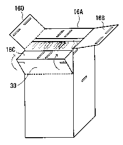
Figure 7 shows the container partially erected with
the front flap 30 folded downwardly. The slots 25 at the upper
ends of the walls 12b and 12d form seats for the ends of a
metal rod 54 intended for the purpose of supporting the hangers
of clothing items (not shown) to be transported within the
container. The rod 54 must be of sufficient strength as to
bear the weight of the contents to be transported, and the ends
thereof are sufficiently broad in relation to the strength of
the wall material, that they can be supported in the slots 25
without damage to the wall material. Figure 8 shows the metal
rod in position at the top of the container, and it will be
observed that with the top flaps extending upwardly and the
front flap 30 folded downwardly, there is generous access to
the interior of the container to facilitate insertion therein
of clothing items suspended on hangers which will be carried on
the metal rod 54.
Once the container has been filled as indicated in
Figure 9 with clothing items (shown in broken lines 56) closing
of the container can be completed. In this connection the
front flap 30 is folded upwardly to be coplanar with the rest
of the front wall 12c with top flap 16c being arranged
horizontally in line with the opposite top flap 16a. At this
stage the remaining top flaps 16b and 16d can be folded to a
horizontal position overlying the top flaps 16a and 16c as
shown in Figure 11 until the condition shown in Figure 12 is
reached and the container is closed. To secure the flaps 16a
to 16b in the closed condition, releasable fasteners in the
CA 02323577 2000-10-13
78970-2
12
form of strips hook and pile closures such as Velcro~ are
provided in registering positions on the flaps as shown at 58
in Figures 9 and 10. The Velcro~ is provided in strips adhered
in corresponding positions on the surfaces of the flaps 16a to
16d and 20a to 20d so that when the flaps are folded as
indicated in Figures 11 and 12, the Velcro strips 58 in the top
flaps 16b, 16d are aligned with and come into engagement with
the Velcro strips 58 on the remaining flaps 16a, 16c thus
securely retaining the flaps in the closed position. Further
releasable Velcro strips 60 are provided to act between the
front flap 30 and the adjacent parts of the side walls 12b and
12d. In this way the front flap 30 is held securely in
position when the container is erected, and the Velcro strips
60 act to strengthen the upper end of the container by
preventing displacement of the front flap 30 under load.
The position of the metal rod 50 at its location
immediately beneath the flaps 16b and 16d means that this rod
provides structural support to the upper end of the container
so that in fact the finished container when erected provides
good resistance against imposed loads applied to its upper end.
The alternative joint configuration shown in Figure
13 between the walls 12A and 12D of the carton avoids the need
to provide a gripper as shown at 34 in Figures 2 through 5.
Instead, a more conventional kind of joint is provided. Here
the edge regions of the sheets 12A, 12D are compressed to form
tongues 72, 74 by crushing the material of the sheet so that
the overlapping tongues have a combined thickness no greater
than that of the sheet material itself. The overlapped tongues
are secured together by any suitable means such as by rivets
76, or by heat-sealing or adhesive indicated at 78.
CA 02323577 2000-10-13
78970-2
13
Although for practical reasons it is preferred that
the joint required to complete the horizontal enclosure formed
by the walls 12A to 12D is positioned at the junction between
the edges of two of the sheets 12A, 12D as shown in Figure 13,
in principle there is no reason why the joint should not be
formed intermediate the length of one of the sides 12A to 12D,
and this is illustrated in Figure 13 where the wall 12A is
shown in broken lines as extending laterally to the left of the
joint. In this event, the corresponding top and bottom flaps
16D and 20D respectively (not shown) would be of composite form
having interruptions therein corresponding to the tongues 72,
74.
A further alternative is shown in Figure 14 where a
representative wall 12X is illustrated as having a joint 78
formed therein. In this case the adjacent edges 80 of the
sheet forming the joint are hollowed out (by removing one or
several of the bridging walls 7) to define a pocket 82 in which
is received an elongate bar 84 of suitable material, e.g.
lightweight plastic, which fills the pockets, the point being
secured together then by any suitable means such as by layers
of adhesive 86 connecting the joint bar 44 to the walls 6, or
by heat sealing or the like. The joint can further or
alternatively be secured by rivets (not shown) as in Figure 13.
To further strengthen the joint adhesive tapes 88 could be
applied to the external surfaces of the walls 6.
The bar 86 would terminate, or at least be
interrupted in the region of the upper and lower creases 18 and
22 to enable the flap associated with the wall 12X to be folded
over.
Since the plastic sheet material is readily
fabricated by extrusion, it could equally well be extruded in
CA 02323577 2000-10-13
78970-2
14
tubular form rather than as a flat sheet. In that event, of
course, no joining arrangement would be necessary thus
eliminating the need for the gripper bar. A tubular formed
section of the material could simply be creased longitudinally
to define corner areas and notched at its ends and creased
circumferentially to define the top and bottom flaps.
Whereas particular embodiments of the invention have
been described above and illustrated in the drawings, it will
be recognized that modifications and variations in the details
thereof may readily occur to those skilled in the art, and
consequently all such modifications and equivalents are
intended to be covered within the scope of the appended claims.