Note: Descriptions are shown in the official language in which they were submitted.
CA 02323624 2000-09-14
WO 00/14739 PCT/1B99/01585 '
DISK PROTECTIVE ENCLOSURE
BACKGROUND
The present invention relates to optical data disks
such as compact disks (CDs) and video disks (DVDs) that have
central circular locating openings, and more particularly to
devices for protectively enclosing such disks for storage of
same.
Data disks such as compact disks and video disks
typically have large amounts of digitally stored information that
is optically readable through a transparent bottom layer of the
disk by a movable head during rotation of the disk. The
information is arranged in one or more tracks that are covered by
a thin protective top layer of the disk that can have labeling
applied thereto such as by silkscreening. Normal handling of the
disk can result in scratching of the bottom layer, resulting in
loss of data by interference with the optical path such as by
loss of focus and/or lateral image displacement. Also, data can
be lost by scratching of the protective layer which is typically
very thin, on the order of 20 microns, resulting in removal of
information from a vapor deposited metal layer that is only about
0.1 micron thick. Protective containers for the disks in common
use have a central pedestal for supportively gripping the disc by
engaging the central opening without contacting either side of
the disk within data-containing regions thereof. Such containers
typically have a Ledge for contacting portions of an outer
perimeter of the disk for stabilizing the disk against tipping on
the pedestal. The disk is loaded into the container by lowering
it onto the pedestal while gripping opposite perimeter portions,
engagement with the pedestal being typically effected by
simultaneous finger pressure against one or more elements of the
pedestal. Removal of the disk is similarly effected by finger
pressure against the pedestal and simultaneous lifting at the
perimeter portions. U.S. Patent No. 5,685,427 to Kuitems et al.
discloses a compact disk holder having a central post that
projects from a shoulder surface, the post having an outwardly
CA 02323624 2000-09-14
WO 00/14739 PCT/IB99/01585 -
2
facing ridge for gripping the disk opposite the shoulder surface.
The post is formed with spiral slots for contraction of segments
in response to finger pressure. A disadvantage of the holder of
Kuitems is that it is difficult to use in that excessive finger
pressure is required for contracting the segments; conversely, if
the segments are made sufficiently long and thin for contracting
under reasonable finger pressure, they are too weak to be
effective in holding the disk.
U.S. Patent No. 5,526,926 to Deja discloses a disk
storage case having a segmented central pin that is formed with
an outwardly projecting collar for gripping the central hold of
the disk, the pin being connected to an outwardly projecting
plurality of lifting fingers that pivot upwardly when the pin is
contracted by pressure on a central push-button. A disadvantage
of the case of Deja is that the fingers are ineffective in that
they must be sufficiently elastic to permit depression of the
push-button prior to actual lifting of the disk, and they do not
retain sufficient elastic strength for reliably lifting the disk,
in that projection portions of the fingers have limited length.
UK Patent Application No. 2,291,640 by Fraser et al. discloses a
compact disk holder having a bifurcated button holder supported
on respective inwardly projecting spring arms, segments of the
holder being interconnected by a living hinge. Spaced about the
button holder are a plurality of inwardly projecting disk
ejection spring arms. The holder of Fraser et al. has a number
of disadvantages. For example:
1. The ejection spring arms are ineffective in
that they contact the disk at some distance from the central
hole, and must overcome flexing of the disk to the extent of any
residual resistance by the holder;
2. The disk is subject to damage by the ejection
spring arms in regions that are sufficiently distant from the
central hole as to compromise the integrity of recorded data; and
3. The ejection spring arms are prone to be
damaged by being snagged by objects such as a user's clothing.
Thus there is a need for a protective disk
container that overcomes the disadvantages of the prior art.
CA 02323624 2000-09-14
WO 00/14739 PCT/IB99/01585 -
3
SUMMARY
The present invention meets this need by providing
a molded holder configuration wherein structural components are
unlikely to be snagged or damaged during normal use and handling,
and that is particularly effective and easy to use. In one
aspect of the invention, a holder for a disk having a central
opening and front and back face surfaces includes a base having a
planar panel portion; a pedestal projecting forwardly from the
base on a pedestal axis, the pedestal including a central button
portion having a plurality of radially outwardly projecting
retainer members and a plurality of axially extending stem
members; a plurality of arm members supporting the retainer
members and the stem members of the button portion in
cantilevered relation to the base, the arm members sloping
radially inwardly and axially forwardly from the panel portion of
the base, the arm members collectively having an extended
position for retaining the disk by engagement of the front face
surface by the retainer members proximate the central opening,
free end extremities of the arm members being deflectable axially
rearwardly from the extended position to a depressed position in
response to applied pressure against the button portion for
producing sufficient corresponding radially inward and axially
rearward movement of the retainer members and the stem members to
permit passage of the retainer portions and the stem portions
through the central opening of the disk; and a plurality of
finger members for biasingly contacting the rear face surface of
the disk proximate the central opening for displacing the disk
axially forwardly relative to the retainer portions when the arm
members are in the depressed position, the finger members being
deflectable into proximate coplanar relation with the arm
members.
Preferably free end extremities of the finger
members have laterally and radially extending enlargement
surfaces formed thereon for distributing contact forces against
the lower disk surface.
CA 02323624 2000-09-14
WO 00/14739 PCT/IB99/01585 _
4
The stem portions can be integrally formed as
button segments with corresponding ones of the retainer members.
Preferably the holder includes a laterally spaced pair of the arm
members connected to each of the stem portions, the arm members
of each pair straddling a respective one of the finger members,
thereby protecting the finger members from being snagged or
otherwise damaged by contact with external objects. Preferably
forwardly facing surfaces of the button surfaces slope forwardly
and inwardly from outer extremities of the retainer members to
respective forward extremities of the button segments, the
forward extremities being sufficiently confined for ramped
engagement with the central opening in the extended position of
the arm members.
Preferably the base portion is formed with a
segmented generally conical projection extending concentrically
with the pedestal axis from the panel portion toward the button
portion, the conical projection including main portions of the
arm members and the finger members for providing a generally
smooth front profile of the pedestal. Preferably the conical
projection further includes a plurality of skirt members
extending between adjacent pairs of the arm members and being
closely spaced therefrom for shielding the arm members.
The base portion can further include an edge
support member projecting forwardly from the panel portion and
having a shoulder surface for contacting the rear surface of the
disk proximate a perimeter extremity thereof and a cylindrical
locating surface extending forwardly of the shoulder surface in
concentric relation to the pedestal axis for augmenting lateral
support of the disk, a pair of finger depressions formed in the
edge support member on opposite sides of the pedestal axis, each
finger depression interrupting the locating surface for
permitting the disk to be gripped by a user's fingers when the
disk extends within the locating surface. The shoulder surface
can be interrupted by the finger depressions. Preferably the
shoulder surface is spaced from the disk in the engaged position
of the arm members for limiting deflection of the disk when the
arm members are being moved to the depressed position.
CA 02323624 2000-09-14
WO 00/14739 PCT/IB99/01585
DRAWINGS
These and other features, aspects, and advantages
of the present invention will become better understood with
reference to the following description, appended claims, and
5 accompanying drawings, where:
Figure 1 is a perspective view of a protective disk
container according to the present invention, the container being
in an open condition;
Figure 2 is a perspective view detailing a central
pedestal portion of the container of Fig. 1, the pedestal
portion being in a relaxed condition;
Figure 3 is a plan view of the pedestal portion of
Fig, 2;
Figure 4 is a sectional elevational view on line 4-
4 of Fig. 3;
Figure 5 is a fragmentary sectional elevational
view, showing a disk positioned preparatory to engagement with
the pedestal portion of Fig. 2;
Figure 6 is a detail view as in Fig. 5, showing the
disk pressed into engagement with the pedestal;
Figure 7 is a detail view as in Fig. 5, showing the
pedestal portion deformed to a contracted condition, the disk
being released therefrom;
Figure 8 is a perspective view as in Fig. 2,
showing the pedestal portion and disk (pictured reduced in
outside diameter) in the relationship of Fig. 7; and
Figure 9 is a sectional elevational view of the
container of Fig. 1 in a closed condition with the pedestal
supporting the disk as in Fig. 6.
CA 02323624 2000-09-14
WO 00/14739 PCT/IB99/01585 -
6
DESCRIPTION
The present invention is directed to a disk
container that is particularly effective for protectively storing
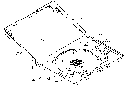
disks such as CDs and DVDs. With reference to Figs. 1-9 of the
drawings, a DVD box 10 includes a case 12 having a transparent
jacket 13 bonded thereto for displaying printed material (not
shown), the case having a base portion 14 a lid portion 16, and a
hinge portion 18 that movably connects the base and hinge
portions. In an exemplary configuration, the case 12 is an
integrally formed molded member, so-called "living hinges" being
formed along opposite edges of the hinge portion 18. The base
and lid portions 14 and 16 include respective panel portions 17
and 19, and respective perimeter side portions 17S and 19S that
conventionally snap together in edgewise adjacency in a closed
condition of the box 10, the hinge portion 18 and the side
portions 17S and 18S together forming four side walls of the case
12, the lid panel portion 17 forming a front wall, the base panel
portion 19 forming a rear wall. The jacket 13 is bonded to the
panel portions 17 and 19 along respective perimeter edge portions
thereof opposite the hinge portion, being open otherwise for
facilitating insertion of the printed material being configured
for covering substantially all of the outer surface of the panel
portions 17 and 19 and the hinge portion 18. In further
description of the case 12, the terms "front" and "forward" with
respect to the base refer to a direction toward the lid portion
16 in the closed condition of the box 10; conversely, "rear",
"rearward", and "back" refer to a direction away from the lid
portion.
A pedestal 20 of the case projects forwardly from
the panel portion 19 of the base 14 on a pedestal axis 21 for
supportively engaging a digital video disk 22 having front and
rear face surfaces 23 and 24, a circular central opening 25, and
a periphery 26. An edge-support portion 28 of case 12 also
projects forwardly on the panel portion 19 in concentric relation
to the pedestal axis 21 for contacting the disk 22 at the
periphery 26. The edge-support portion 28 is formed with an edge
CA 02323624 2000-09-14
WO 00/14739 PCT/IB99/01585 -
7
shoulder 30 for stabilizing the disk 22 against tipping, and a
cylindrical locating surface 32 for augmenting lateral support of
the disk 22 while the disk is engaged with the pedestal 20. The
edge-support portion is also formed with at least one pair of
finger depressions 34 for permitting opposite perimeter portions
of the disk 22 to be grasped by a user of the container 10, the
edge shoulder 30 and the cylindrical locating surface 32 being
interrupted by the finger depressions 34.
According to the present invention, the pedestal 20
is formed with a plurality of stem portions 36, and retainer
portions 38 being angularly spaced about the pedestal axis 21 and
supported at free ends of angularly spaced arm members 40, the
arm members being cantilevered and sloping radially inwardly and
axially forwardly from the base 14 and being sufficiently
flexible for movement between an extended position wherein the
retainer portions 38 contact the front surface 23 of the disk 22
with the stem portions 36 projecting into the central opening 25
as shown in Figs. 6 and 9, and a depressed position wherein the
retainer portions 28 and the stem portions 36 are displaced
axially rearwardly and radially inwardly for clearing the central
opening 25 as shown in Figs. 7 and 8. Inner extremities of the
arm members 40 are formed with respective contact portions 41
that extend generally in coplanar relation parallel to the base
panel portion 19. The pedestal 20 also includes a plurality of
finger members 42 having respective contact portions 43 for
urging the disk 22 axially forwardly relative to the retainer
portions 38, thereby to facilitate disengagement of the retainer
portions 38 from the upper disk surface 23 and passage of the
retainer portions into the central opening 25. The contact
portions 43 of the finger members are enlarged laterally as best
shown in Fig. 3 for limiting concentrations of the biasing forces
against the rear surface 24 of the disk 22. The finger members
42 are protected from damage by being located in close proximity
with the arm members and being oriented approximately parallel
therewith as further described below.
In the exemplary and preferred configuration of the
pedestal 20 as shown and described herein, respective ones of the
stem portions 36 and retainer portions 38 are integrally formed
CA 02323624 2000-09-14
WO 00114739 PCT/IB99/01585 _
8
as corresponding button segments 44, each button segment 44
having a conical chamfer surface 39 that extends to outer
extremities of the stem and retainer portions 36 and 38. Each of
the button segments 44 is supported by a generally parallel-
s spaced pair of the arm members 40, and each of the finger members
42 extends between a corresponding pair of the arm members 40 in
generally parallel spaced relation thereto. In a relaxed
condition of the pedestal 20 as best shown in Fig. 2, the finger
members 42 extend slightly forwardly of the arm members 40, outer
extremities of the arm members 40 and the finger members 42
extending to the base panel portion 19 and being joined thereto
along a circular outer perimeter 45 of the pedestal 20, the
perimeter 45 being coplanar with a front surface of the panel
portion 19. Thus the finger members 42 are protected from
breakage by being located in generally co-conical relation with
the arm members 40. When the disk 22 is latched onto the
pedestal 20 with the retainer portions 38 contacting the front
disk surface 23, the back disk surface 24 rests on or proximate
the contact portions 41 of the arm members 40, the contact
portions 41 being thus approximately coplanar with the contact
portions 43 of the finger members 42. In this condition of the
pedestal 20, further downward deflection of the finger members 42
relative to the arm members 40 is prevented by the disk 22
contacting the arm member contact portions 43. Further, the
combination of the arm members 40 and the finger members 42
advantageously provides a greatly increased resistance to further
downward movement of the disk proximate the central opening 25
thereof.
The arm members 40 are also protected from breakage
or permanent deformation by the pedestal 20 further including a
plurality of skirt members 46 that extend inwardly and forwardly
from the outer perimeter 44 in approximately co-conical relation
to the arm members 44, each of the skirt members 46 being closely
spaced edgewise from a divergent pair of the arm members 40. In
the relaxed condition of the pedestal 20, the arm members 40 in
combination with the skirt members 46 form an advantageously
smooth frusto-conical front face of the pedestal 20 that extends
from the base panel 19 at the outer perimeter 44 inwardly and
CA 02323624 2000-09-14
WO 00/14739 PCT/IB99/01585
9
forwardly to the contact portions 41 of,the arm members 40. Thus
the arm members 40 as well as the button portions 41 are
protected from being caught and possibly being damaged by contact
with objects such as clothing of a user of the container 10. The
finger members 42, in addition to the protections described
above, extend inwardly to proximate the retainer portions 38 in
the relaxed condition of the pedestal 20. This further protects
the finger members, the retainer portions 38 serving to shield
the ends 43 of the finger members from being bumped or snagged by
extraneous objects during normal handling of the container 10
when the disk 22 is removed and the lid portion 16 is open.
Although the present invention has been described
in considerable detail with reference to certain preferred
versions thereof, other versions are possible. Therefore, the
spirit and scope of the appended claims should not necessarily be
limited to the description of the preferred versions contained
herein.