Note: Descriptions are shown in the official language in which they were submitted.
CA 02323944 2000-09-14
WO 99/49155 PCT/CA99/00246
-1-
RETROFITTING EXISTING CONCRETE COLUMNS BY EXTERNAL
PRESTRESSING
F i~ld of the Invention
This invention relates generally to reinforced concrete structures and more
particularly it is directed to concrete columns in buildings, bridges, and
other types of
structures.
Background of the Invention
Concrete columns are used in buildings, bridges and other structures to
support
axial compression and resist flexural and shear stresses. They are often
reinforced with
reinforcement consisting of longitudinal and transverse steel. The
longitudinal
reinforcement contributes to axial and flexural resistance. The transverse
reinforcement
contributes to improving shear (diagonal tension) capacity, preventing or
delaying
buckling of longitudinal reinforcement in compression, and confining concrete
to improve
strength and deformability of concrete. While the amount of longitudinal
reinforcement
affects flexural and axial strength, it does not play a significant role on
column
deformability. However, the transverse reinforcement plays a vital role on
column shear
strength and deformability. Columns are often required to be designed with
sufficient
transverse reinforcement, in the form of ties, hoops, overlapping hoops and
crossties for
excess shear capacity to prevent premature shear failure, which is regarded as
a brittle
fozm of failure. Hence, in properly designed concrete columns, brittle shear
failure never
precedes ductile flexural failure.
The same transverse reinforcement also improves flexural performance if placed
with sufficiently small spacing. Closely spaced transverse reinforcement
provides a
CA 02323944 2000-09-14
WO 99/49155 PCT/CA99/00246
-2-
reinforcement cage which confines the compression concrete. Concrete in
compression
develops a tendency to expand laterally due to the Poisson's effect. Lateral
expansion
generates transverse tensile strains and longitudinal splitting cracks which
eventually
result in failure. The presence of closely spaced transverse reinforcement
controls the
development of splitting cracks and delays the failure of concrete. Lateral
expansion of
concrete is counteracted by passive confinement pressure exerted by
reinforcement. The
resulting confinement action enhances both the strength and deformability of
concrete.
These improvements directly translate into flexural strength enhancement, as
well as a
very significant increase in inelastic deformability.
Performance of buildings and bridges during recent earthquakes indicated
serious
design deficiencies, especially when stresses exceed elastic limits of
materials. For
example, the majority of bridge failures in the 1994 Northridge Earthquake
were attributed
to lack of shear and/or confinement reinforcement in columns. Similarly, a
large number
I 5 of building failures during past earthquakes have been attributed to poor
column behavior,
especially due to lack of shear/confinement reinforcement. A large number of
bridges
were found to have seismic deficiencies in the State of California alone.
These structures
need to be retrofitted for improved strength and ductility.
Columns of multistory buildings are often critical at the first story level,
where
they may be subjected to plastic hinging due to excessive flexural stress
reversals, or shear
distress caused by high seismic shear forces. These columns are often fixed to
the
foundation, and are built monolithically with the structure. Hence, they often
deform in
double curvature, developing high flexural stresses at the ends, near the
supports, where
they are restrained against bending. These end regions may become critical for
flexure.
High flexural tensile stresses may develop, causing the column longitudinal
reinforcement
yield, initiating ductile response until compressive stresses in concrete
result in the
crushing of the concrete. Concrete crushing is a brittle form of failure,
leading to sudden
and immediate loss of strength. One viable approach to prevent the brittle
failure of
CA 02323944 2000-09-14
WO 99/49155 PCTICA99/00246
-3-
concrete in compression is to provide lateral confinement. Confined concrete
is laterally
restrained against possible expansion. Axially compressed concrete can not
crush unless it
expands laterally due to the Poisson effect and develops vertical tensile
cracks. The Lateral
pressure provided by confinement overcomes the tendency to expand, improving
strength
and ductility of concrete. In new construction the building code requirements
for
internally placed transverse confinement reinforcement results in sufficient
lateral
confinement to improve deformability of columns. In existing columns, however,
built
prior to the development of current code provisions, lack of properly designed
transverse
reinforcement results in brittle failures. Hence these columns fail due to
compression
crushing of concrete unless retrofitted externally to provide the required
confinement.
Similar critical regions may develop in bridge columns. These columns are
built to
be fixed against flexural rotation at their footings. Hence, the column end
near the footing
may be critical against flexure and hence compression crushing. Certain bridge
columns
are monolithically built with the bridge deck. These columns may also have a
critical
region near the deck. However, bridge columns may also have a hinge support at
their
ends near the deck. The latter category of columns are not subjected to
significant flexure
near the deck, and hence are not critical at this location.
Confined concrete also provides proper anchorage to reinforcement. Therefore,
lap
splice regions of longitudinal reinforcement are often required to be
confined, if the bars
are at or near the potential hinging regions. Hence, confining concrete also
results in
beneficial effects in lap splice regions.
Both building and bridge columns may attract significant shear forces if they
are
short. Short and stubby columns may be critical in shear, developing diagonal
tension and
compression failures along their heights. Diagonal tension failure in a
concrete column
occurs when transverse column steel is not adequate. In such a case, the
column fails
prematurely, prior to developing its flexural capacity. While flexural
yielding and
CA 02323944 2000-09-14
WO 99/49155 PCT/CA99/0024b
-4-
associated flexural hinging may lead to ductile response, especially if the
column is well
confined, diagonal tension failure results in a sudden and brittle failure.
Therefore, these
columns must be retrofitted externally to prevent brittle shear failure.
Although rare, some
shear-dominant columns may experience diagonal compression crushing of
concrete if
diagonal shear failure is prevented by excessive transverse reinforcement.
Concrete
confinement helps in this case, improving the behavior of concrete against
diagonal
compression.
It is clear from the above discussion that the transverse reinforcement plays
a
significant role on inelastic deformability of concrete columns . While
properly designed
transverse reinforcement is required by building codes in all new columns, its
function can
be fulfilled by external prestressing in old and existing columns which may
not possess
adequate transverse reinforcement. Retrofitting through external prestressing
has the
added advantage of providing actively applied lateral pressure. Active lateral
pressure
delays the formation of diagonal shear cracks in columns, and limits widths of
such
cracks, improving aggregate interlock and consequently increasing concrete
contribution
to shear resistance. The active pressure also increases lateral confinement
and enhances
the mechanism of concrete confmernent, while also restraining longitudinal
reinforcement
against buckling.
The most commonly used prior art for column retrofitting is steel jacketing.
Steel
jacketing involves covering the column surface by steel plates, welding the
plates to form
a sleeve, and filling the gap between the steel and concrete by pressure
injected grout. The
steel jacket overcomes diagonal tensile and compressive stresses generated by
shear, while
also restraining concrete against lateral expansion, thereby confining the
column for
improved deformability. In circular columns, passive confinement pressure is
developed
from hoop tension in the steel jacket as the concrete expands laterally.
However, the same
mechanism cannot be utilized in square and rectangular columns, unless the
column is first
re-shaped to have an elliptical or circular shape before a steel jacket is put
in place. The
CA 02323944 2000-09-14
WO 99149155 PCT/CA99/00246
-5-
steel jacketing can be quite costly because of the large amounts of steel used
and each steel
jacket has to be custom made especially for non-circular columns. However,
because of
lack of availability of a more practical and economical technique, steel
jacketing forms
the majority of recent applications for column retrofitting.
Jacketing concrete columns can also be done by providing a reinforced concrete
sleeve around existing columns. This technique requires placement of
reinforcement cage
around the existing column which may be quite cumbersome especially because of
the
substantial amount of closely spaced transverse reinforcement that has to be
placed around
the column. Another complication is to provide the formwork and place concrete
in the
sleeve. The mechanism of confinement and shear force resistance remains the
same as
that for steel jacketing.
Another retrofitting technique, that is being researched and developed for
concrete
columns, is fiber wrap, involving fiber reinforced polymer (FRP) materials.
This
technique involves covering the surface of concrete column by an FRP wrap,
which
provides passive confinement pressure as the concrete expands laterally under
compression. While this technique was proven to be effective for concrete
confinement,
its use against diagonal tension caused by shear is still questionable.
Furthermore, the
high cost of material, the emission of toxic odors that can harm individuals
in indoor
applications and the lack of experience with long term durability of the
material appear to
be disadvantages that currently prevent widespread use of this technology.
Although the
application of FRP in circular columns shows promising results, in the case of
rectilinear
or polygonal columns, this technique has some drawbacks such as lack of
concrete
confinement and brittle failures at sharp corners of the columns. The above
prior art
techniques are discussed in the US patent 5,680,739 which issued to Cercone et
al on
October 28, 1997.
CA 02323944 2000-09-14
WO 99/49155 PCT/CA99/00246
-6-
From the foregoing discussion, it is concluded that an economically viable,
structurally effective and durable, and practically superior retrofitting
technique is needed
in the construction industry for concrete columns. The need to upgrade
concrete columns
remains a challenge to structural engineers, especially in seismically active
regions.
SummarX,Qf~~e Invention
It is therefore an object of the present invention to provide a method and
hardware
for retrofitting concrete columns by externally prestressing them.
This and other objects are achieved in a process and hardware for retrofitting
concrete columns to improve resistance of concrete structures against abnormal
loads,
such as those encountered during earthquakes and bomb blasts, which are likely
to create
inelasticity in columns.
The method of retrofitting a concrete column comprises the steps of
determining
reinforcement requirements for the column to be retrofitted and selecting
appropriate
hoops for mounting about the column to impart lateral stress to the column.
The hoops
include strands that encircle the column with the ends joined by an anchor.
The hoops are
mounted about the column at predetermined spaced vertical locations. The
tension of the
strands in the hoops is adjusted to meet the predetermined reinforcement
requirements. In
addition, the hoops or the hoops and the column may be covered with a
protective coating.
In accordance with another aspect of the invention, requirement for
reinforcement
may be determined by calculating if VP,~b z V" where VP,~ is the probable
shear force and
V" is the design shear capacity of the column. In addition, if the existing
transverse in the
column does not conform to predetermined confinement steel requirements,
retrofitting of
the column is required.
CA 02323944 2000-09-14
WO 99/49155 PCTlCA99/00246
In addition, to compensate the shear deficiency in a column, A~,,~,~~ - the
cross-sectional
area of a high-tensile prestressing strand in mm2 is calculated; to compensate
the
confinement deficiency in a column, As".~""f"e - the cross-sectional area of a
high-tensile
prestressing strand in mm2 is calculated. Strand selection is then based on
the larger of the
two cross-sectional areas A,rrr-.rhear ~d Asrr-co"fr"e.
Axrr-shear is determined from the equation:
_ Cyprob yu ~ str
_ N
Astr-shear 2 1- a f
f ~~ str J ystr
where Vprob 1S the shear force corresponding to probable flexural resistance
of the column
and may be taken as 1.25 times the nominal flexural capacity of the column
divided by the
shear span in newtons (N); V;, is design shear capacity of the column in N;
ssr is the
spacing of the hoops in the longitudinal direction in mm; ~ is the inclination
of the
assumed failure surface caused by diagonal tension and may be taken as
45°; afis the ratio
of initial prestress to yield strength of the strand; ~srr is the capacity
reduction factor of the
strand that can be taken as 0.9; f ,." is the yield strength of strand in MPa;
and b is the
diameter of a circular column or the cross-sectional side dimension of a
rectilinear column
in the direction of shear force in mm.
It has been determined that the first hoop may be placed at approximately 75
mm
above the base of the column and the other hoops at intervals of b/4 or 150 mm
whichever
is the lesser.
An,..~o"~"e is determined from the equation:
f'~ bs Pc
Astr-confcne ~ ~ 4 -+~ 50
fystr 1 ~~~ Por
CA 02323944 2000-09-14
WO 99/49155 PCTICA99100246
_g_
where f ~ is the compressive strength in MPa as determined by a standard
cylinder test;
JYSfI is the yield strength of the strand in MPa; b is the diameter of a
circular column or the
cross-sectional side dimension of a rectilinear column parallel to the axis of
bending in
mm; s~" is the spacing of the hoops in the longitudinal direction in mm; Pfis
the factored
axial compressive force due to the combination of gravity and lateral loads in
N and P~, is
the factored concentric capacity of the column in N.
Another aspect of this invention is a number of kits for retrofitting concrete
columns having a curved surface or substantially flat surfaces. All kits
include a plurality
of high tensile strands for mounting about the column that can be in the form
of one or
more strand lengths and a plurality of anchors for joining the two ends of the
strands under
tension. The kits for the columns with substantially flat surfaces further
include a plurality
of raisers for placement between each strand and adjacent flat surfaces of the
column as
well as a plurality of corner spacers or raisers for placement between each
strand and
adjacent corners formed by adjacent flat surfaces. In addition, the raisers
between the
strand and the substantially flat surfaces are constructed such that the
strand will form an
approximate parabolic curve where the ratio between the length of the flat
surface and the
perpendicular distance between a line joining the ends of the parabolic curve
and the peak
of the parabolic curve is in the order of 5 to 10 : 1.
In accordance with another aspect of this invention, the anchor for joining
two
strand ends under tension comprises a block having two adjacent holes passing
through the
block and defining adjacent paths that twist around one another resulting in
adjacent
openings on opposite ends of the block. The holes are adapted to receive the
ends of the
strands. In addition, one opening for each hole located at opposite ends of
the block has
tapered walls for receiving a tapered wedge, the wedges fix the ends of the
strand under
tension within the block.
CA 02323944 2000-09-14
WO 99/49155 PCT/CA99100246
-9-
Many other objects and aspects of the present invention will be clear from the
detailed description of the drawings.
Brief Desc3iption of the Drawings
Embodiments of the invention are described with reference to the drawings in
which:
Figure 1 (a) is an elevation view of a typical building column to which this
invention may be applied;
Figure 1 {b) is an elevation view of a typical bridge column to which this
invention
may be applied;
Figure 2(a) is a cross section view of a circular column;
Figure 2(b) is a cross section view of a rectilinear column;
Figure 2(c) is a cross section view of a polygonal column;
Figure 3 is an elevation view of part of the circular column showing
prestressing
hoops mounted about the column;
Figure 4 is a schematic view of anchor system consisting of prestressing wire,
wedges, and the nozzle of the anchor;
Figure 5(a) is an elevation view in cross-section of a Dywidag anchor;
Figure 5(b) is a horizontal view in cross-section of a Dywidag anchor;
CA 02323944 2000-09-14
WO 99/49155 PCTICA99/00246
- 10-
Figure 6(a) is an elevation view in cross-section of the anchor device in
accordance
with an aspect of the present invention;
Figure 6(b) is a horizontal view cross-section of the anchor device described
in
figure 6(a);
Figure 7 is an elevation view of part of the circular column showing
prestressing
cables wrapped around the column and a continuous anchor;
Figure 8 is an elevation view of the anchorage system described in figure 7;
Figure 9 is a cross section view of a retrofitted circular column with a
protective
encasement;
Figure 10(a) is an elevation view of one embodiment of a retrofitted square
cross
section column;
Figure 10(b) is a cross-section of the retrofitted square cross-section column
described in figure 10(a);
Figure 11 (a) is an elevation view of part of a retrofitted rectilinear
column;
Figure 11 (b) is a cross-section of the retrofitted rectilinear column
described in
Figure 11 (a);
Figure 12(a) is an elevation view of the raiser used for retrofitting
rectilinear
columns as described in figures 11 (a) and 11 (b);
Figure 12(b) is a horizontal view of the raiser described in figure 12(a);
CA 02323944 2000-09-14
WO 99/49155 PCTICA99/U0246
-11-
Figure 13(a) is an elevation view of the corner raiser used for retrofitting
rectilinear
columns as described in figures 11 (a) and 11 (b);
Figure 13(b) is a partial horizontal view of the corner unit described in
figure
13(a);
Figure 13 (c) is a partial front view of the corner unit described in figure
13(a);
Figure 14(a) is a graph of the performance of a "as designed" circular column
in a
cyclic test;
Figure 14(b) is a graph of the performance of a "retrofitted" circular column
in a
cyclic test;
1 S Figure 15(a) is a graph of the performance of a "as designed" square
column in a
cyclic test; and
Figure I5(b) is a graph of the performance of a "retrofitted" square column in
a
cyclic test.
Detailed Description of the Drawings
Figure I(a) shows a typical building column la resting between floor slabs 2.
Figure 1(b) shows a typical bridge column 1b resting between the bridge deck 4
and the
foundation 5. The columns 1 a in buildings are monolithic 3 to the floor slabs
2, whereas in
bridges the columns I b are monolithic 3 to the foundation 5 and monolithic 3
or hinged 6
to the bridge deck 4. The columns la or 1b are normally made out of concrete
material
with or without embedded vertical reinforcing steel and transverse hoops or
ties.
CA 02323944 2000-09-14
WO 99/49155 PCTICA99/00246
-12-
Columns 1 a and 1 b come in different shapes and sizes. Figure 2(a)
illustrates a
cross-section of a circular column 1 a or 1 b, figure 2(b) illustrates a cross-
section of a
rectilinear column 1 a or 1 b, and figure 2(c) illustrates a cross-section of
a polygonal
column 1 a or 1 b which in this particular case is a hexagonal column 1 a or 1
b.
During severe loading, such as an earthquake, the column 1 a or 1 b is
subjected to a
lateral load as well as its own weight acting as an axial load. The top and
bottom ends of
the columns la or 1b having monolithic connections 3 are subjected to double
bending
action and their corresponding shear span may be shorter than the actual
column length L.
The bottom end of the columns la or 1b having monolithic connections 3 and top
end of
the columns having hinged connections 6 are subjected to single bending action
and their
corresponding shear span may be taken as the full column length L.
The present invention involves retrofitting columns such as those illustrated
in
Figures la, 1b, 2a, 2b and 2c among others to increase strength and
deformability
(ductility) of the concrete columns during seismic and similar extreme events,
including
explosions. For the concrete columns that require it, the strength and
deformability of the
concrete columns can be improved to better withstand seismic shear and
flexural force
reversals. The retrofits in accordance with the present invention are carned
out on
location.
The retrofit method in accordance with the present invention comprises the
following steps for any particular column which is being considered for
retrofitting:
1- Calculate the design shear capacity Y" in the column;
2- Determine the shear force VProb corresponding to probable moment capacity
by
performing a sectional analysis in any manner known to one skilled in the art
as
presently required by the ACI 318-95 Building Code or the CSA A23.3 Standard.
CA 02323944 2000-09-14
WO 99/49155 PCTICA99100246
-I3-
3- The probable shear force Vp,~b determined in step 2 is compared to the
design shear
capacity V". If Vprob z Vu, then retrofitting is required. If however the
probable
shear force Vprob is smaller, retrofitting is not required because of a
deficiency in
S shear, but may still be required to confine concrete to assure sufficient
deformability (ductility).
4- If the existing transverse reinforcement in the column does not conform to
the
confinement steel requirements spelled out in the most recent building code,
retrofitting of the column is required.
Steps I to 4 are carried out to determine if a particular column requires to
be
retrofitted in order to meet the deformability requirements.
I 5 The process for retrofitting columns in accordance with the present
invention
comprises the external application of hoops made with strands with their ends
joined under
tension around the column at discrete locations throughout the column length.
These
hoops are stressed to provide near uniform lateral pressure on the column face
at these
discrete locations. The level of prestressing that is applied to the strands
in the hoops may
be set at from substantially zero which provides a snug fit to 40% of f 5l,
which is the yield
strength of the strand in MPa, however up to 25% of f s" is preferred.
The prestressing force applied to concrete columns overcomes diagonal tensile
forces generated during seismic excitation and eliminates premature shear
failure. It also
applies lateral pressure to confine concrete. Confined concrete exhibits
ductile
characteristics and does not crush in a sudden and explosive manner under
seismic
induced compressive stresses. Hence, columns retrofitted with external
transverse
prestressing show improved strength and ductility, which are the two most
important
qualities sought for seismic resistance of any structural element. Research
showed that
CA 02323944 2000-09-14
WO 99/49155 PCT/CA99100246
- 14-
active and evenly distributed pressure applied on the column face has
significantly
improved the column's deformation behavior by eliminating premature shear
failure while
increasing confinement for improved strength and ductility.
When retrofitting is required due to a deficiency of shear, ie VPwb Z Vu, the
required
cross section area in mm2 As"-,.,,ea, of the high-tensile strand in a hoop is
given as the
following:
_ [yprob ~u ~str
H
~str-shear 2 1- a ~'
f ~~ str J ystr
where Vpob 1S the shear force corresponding to probable flexural resistance of
the column
and may be taken as 1.25 times the nominal flexural capacity of the column
divided by the
shear span in newtons (N); V~ is design shear capacity of the column in N;
s,Y,r is the
1 S spacing of the hoops in the longitudinal direction in mm; O is the
inclination of the
assumed failure surface caused by diagonal tension and may be taken as
45°; afis the ratio
of initial prestressing strength to yield strength of the strand; ~.5.,~ is
the capacity reduction
factor of the strand that can be taken as 0.9; f"r is the yield strength of
strand in MPa; and
b is the diameter of a circular column or the cross-sectional side dimension
of a rectilinear
column in the direction of shear force in mm.
The spacing, s5.", of the external strands must be at b/4 or 150 mm, whichever
is
less, for confinement of concrete and stability of longitudinal reinforcement.
This follows
very closely design requirements for the placement of transverse reinforcement
hoops in
the columns. The first external strand must be positioned not more than 75 mm
away
from the bottom end of the column.
When retrofitting is required due to a deficiency of confinement, the required
cross
section area in mm2 A$".~o"f"r of the high-tensile strand in a hoop is given
as the following:
CA 02323944 2000-09-14
WO 99/49155 PCT/CA99/00246
-15-
f ~ bs Pr
>_ ( 4+50
str confine
fys~ 1000 Por
where f ~ is the compressive strength in MPa as determined by a standard
cylinder test;
fir, is the yield strength of strand in MPa; b is the diameter of a circular
column or the
cross-sectional side dimension of a rectilinear column parallel to the axis of
bending in
mm; s~r is the spacing of the hoops in the longitudinal direction in mm; P f
is the factored
axial compressive force due to the combination of gravity and lateral loads in
N and P~, is
the factored concentric capacity of the column in N.
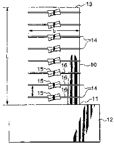
Figure 3 illustrates one embodiment of the application of the present
invention to a
circular concrete column, such as a bridge column where the base of the column
is
monolithic 11 with the footing 12 and the top is hinged 13. A plurality of
prestressing
hoops 14 which include strands 16 that encircle the column 10 and are joined
by anchor
devices 15. In this particular example, the first hoop 14 is positioned 75 mm
from the
footing 12 and all subsequent hoops 14 are positioned 150 mm apart. It is to
be noted that
a large variety of elements may be used as strands 16, such as prestressing
wire, seven
wire strands, carbon fiber strands as well as other metal or non-metal straps,
cables, wires,
bands and the like that can provide the lateral stress necessary for the
column 10 over a
long period of time.
FIG. 4 shows a typical anchor connection used in a hoop 14 around the column
10.
It includes a high-tensile strand 16, an anchor 17, and wedges 18. The strand
16 is pulled
or stressed in the direction of the arrow 19. Once the desired stress level in
the
prestressing strand 16 is reached, the wedges 18 are pushed into the tapered
opening 20 of
anchor 17 while holding the prestressing strand 16 stationary. Once the wedges
18 are
firmly placed into the anchor 17, the prestressing strand 16 is released and
wedges 18 grip
the prestressing strand 16 with pure friction.
CA 02323944 2000-09-14
WO 99/49155 PCT/CA99/00246
- 16-
One anchor device which can be used in the implementation illustrated in
figure 2
is one developed by Dywidag-Systems International. This anchor device 20 is
shown
schematically in cross section in figure Sa and Sb. Anchor 21 comprises a
block of cast
iron 22 with two holes 23 and 24 running through its length. Each hole 23 and
24 has a
tapered opening to receive a split cylindrical tapered wedge 25 and 26
respectively to bind
the ends 27 and 28 of strand 29 to the anchor 21. As can be seen in figure
5(b), when
tension is place on the strand 29, the anchor 21 will rotate in the plane of
the drawing
which can result in stress concentration points on the strand 29 at the edge
of the anchor
21. Alternate anchoring systems have been developed.
One such anchor 31 is illustrated in figures 6(a) and 6(b). Anchor 31
comprises a
block of cast ductile iron 32 with two holes 33 and 34 running through its
length. Each
hole 33 and 34 has a tapered opening at opposite ends to receive a split
cylindrical tapered
wedge 35 and 36 respectively to bind the ends 37 and 38 of strand 39 to the
anchor 31.
Anchor 31 further includes a curved surface 40 that allows full contact with
the curved
surface of the column 41. In addition, the center lines of the strand 39 as
they exit both
ends of anchor 31 subtend an angle somewhat less than 180 ° between
them such that the
strand 39 lies close to the column 41 without being forced to bend sharply. In
addition as
can be seen in the side view in figure 6b, the strand paths through anchor 31
twist around
one another such that the four openings at the two ends of the anchor 31 all
fall
substantially along a common plane. Thus in operation, when tension is applied
to the
strand 39, rotation of the anchor 31 is minimized avoiding stress points in
the strand 39
caused by sharp bends.
Figures 7 and 8 show an alternative manner of anchoring the ends of the
prestressing strands 47 along a column 43 to form hoops 44 . It includes a
hollow
structural steel beam (HSS) 45 having a series of spaced pairs of holes 46 to
receive the
ends of strands 44. The ends of the strands 44 are fixed against the beam 45
by cylindrical
CA 02323944 2000-09-14
WO 99/49155 PCT/CA99/00246
- 17-
anchors 48. The cylindrical anchor 48 consists of a solid cylindrical block 49
with a
conical hole 50 along its axis through which is passed the strand 44. Split
conical wedges
51 are placed into the conical hole SO with the prestressing wire 44. The
cross sectional
dimensions of HSS 45 depends on the amount of prestressing required on strands
44 and
spacings between the strands 44.
The stressing procedure is done similarly to the procedure described
previously
with respect to figure 3. One end of the prestressing strand 44 is fixed with
wedge 51
inside the cylindrical anchor 48. The other end of the prestressing strand 44
is wrapped
around the column 43 and passed through HSS 45 and a second cylindrical anchor
48.
Strand 44 is stressed or pulled using a hydraulic jack system and is fixed by
the friction of
the wedge 51 in the cylindrical anchor 48 at the release of the pressure on
the prestressing
wire 44.
It has been found to be desireable to protect the retrofitting devices against
corrosion, fire and vandalism, as well as to render the final product more
esthetically
acceptable. To this end, the column 60 with its associated retrofitting hoops
61 may be
covered with some form of encasement 62 as shown schematically in figure 9. It
is to be
noted that the encasement 62 does not contribute to the strength of the column
60.
Though for discussion purposes, column 60 is round, it is to be understood
that the
application of an encasement 62 on other shapes of columns is equally as
important,
feasible and desirable. The form that the encasement 62 will take, will depend
on the
location and protection needs of the column 60. An encasement 62 can be placed
around
the retrofitted column 60 in the form of regular small-aggregate type concrete
mixture
which can be poured into a formwork or pressure grout can be injected into a
formwork
using a standard grouting procedure. Alternately, shotcreeting, a standard
procedure used
in the industry may be employed. In other situations, such as in the
retrofitting of
rectangular columns or columns within buildings, a ready-made thin shell made
out of
materials such as gypsum, concrete, steel, any fiber composite, natural stone
(granite or
CA 02323944 2006-03-13
1g
marble or equivalent) could be utilized. Columns 60 in which a concrete, grout
or
shotcreeting type of encasement 62 is required, must have their surfaces
prepared
prior to the installation of the retrofitting devices. This entails chipping
or roughening
the concrete using standard chipping equipment and sprayed with a bonding
agent and
anti-corrosion coating such as SikaTop Armatec 110, a Sika AG trade-mark for a
polymer modified mortar, in order to bond the existing concrete surface to the
new
cement-based application. In other situations, a simple coat of paint may
provide all
of the protection required.
As discussed previously, the present application is equally applicable to
columns with cross-sections other than curved cross-sections such as circular
or
elliptical, i.e. to column shapes having substantially flat surfaces such as
square,
rectangular, octogonal and the like. Figures 10(a) and 10(b) illustrate one
embodiment
that the retrofitting devices can take. Column 70 is illustrated as being
square and has
a number of hoops 71 mounted along the elevation of the column 70. As in
previous
embodiments, each of the hoops 71 includes a strand 72 and an anchor 73 to
join the
ends of the strand 72 under stress when mounted about the column 70. However,
in
addition, in view of the flat surfaces 74 on column 70, raisers 75 are placed
between
the flat surfaces 74 of the column 70 and the strand 72. In this particular
embodiment,
the raiser 75 for each flat surface 74 includes a square cross section hollow
structural
steel beam 76 cut to the length of the flat surface 74 and a number of half
discs 77
placed between the beam 76 which is lying flat against the column surface 74
and the
strand 72. The number and size of the discs 77 used at each flat surface 74
will depend
on the size of the flat surface 74. It is preferred that the curve formed by
the strand 72
pressed against the discs be somewhat parabolic in order to apply a relatively
equal
lateral force against the surface 74 of the column 70. In order to achieve
this the ratio
of the length 1 of the surface 74 to the maximum distance r of the strand 72
from the
surface 74 should be in the order of 5 to 10 : 1. If surface 74 is is some
curvature to it,
discs 77 need not be as large to obtain the desired parabolic curve. Further,
3i4 discs 77
are placed in the corners of the column 70 to provide a smooth curve for the
CA 02323944 2000-09-14
WO 99/49155 PCTICA99100246
-19-
strand 72 and to protect the corners from excessive pressures. In addition,
the curved
edges of the half disc 77 may have channels in them to secure the strand 72
within them.
Figures 1 I {a) and i 1 {b) illustrate a further embodiment that the
retrofitting devices
can take on columns having flat surfaces. Column 80 is illustrated as being
square and has
a number of hoops 81 mounted along the elevation of the column 80. As in
previous
embodiments, each of the hoops 81 includes a strand 82 and an anchor 83 to
join the ends
of the strand 82 under stress when mounted about the column 80. However, in
addition, in
view of the flat surfaces 84 on column 80, a system of raisers 85 and 86 is
placed between
the column 80 and the strand 82. The flat surface raiser 85 which will be
described in
detail with respect to figures 12(a) and 12(b) is designed to apply a
relatively equal lateral
force against the flat surface 84 of the column 80. The corner raisers 86
provide
continuity between adjacent raisers 85 and a smooth transition of prestressing
strand 82
between adjacent flat surfaces 84 of the column 80. In this particular
embodiment, it has
been found convenient to place the anchor 83 on top of one of the corner
raisers 86 and the
stressing of prestressing strand 82 is applied from this location, however,
this need not be
the case in all applications.
FIG. 12 (a) shows an elevation view of the raiser 85. It has a parabolic
curved
edge 87 with a similar parabolic-shaped channel 88. The depth of channel 88 is
about half
the prestressing strand 82 nominal diameter in order to properly seat the
prestressing
strand 82. Serni-circular openings 86 are located in the raisers 85 to reduce
the weight of
the raisers 85 without sacrificing their strength and to provide easy flow of
concrete or
grout for the construction of an encasement, when required. The bottom portion
of the
raisers 85 include a channel 89 for connection to the corner raisers 86. Once
again, the
length 1 to height r ratio of the raiser should be in the order of 5 to 10 :
1.
Figures 13(a), 13(b) and 13(c) illustrate the corner raiser 86 which includes
a'/4
disc corner element 90 connecting two legs 91. The edge of the element 90
includes a
CA 02323944 2000-09-14
WO 99/49155 PCT/CA99/00246
-20-
channel 92; the depth of the channel 92 is about half of the nominal diameter
of the strand
82 to properly seat the strand 82. The legs 91 of the corner raiser 86 are
adapted to slide
into the channels 89 of raisers 85. These are secured together in place by
bolts placed in
slots 92 in the raisers 85 and the matching slots 93 in the corner raisers 86.
The angle ~,
between the legs 91 shown in the this figure is 90°. However, this
invention is applicable
to all polygonal cross sectional columns 80 and thus the angle may be
different then 90°.
Cyclic tests were performed on two identical circular columns which were
constructed to reflect a pre-1970 construction practice resulting in a
deficient column
under present codes. One of the columns 10 was tested "as designed" and an the
other
column 10 was "retrofitted" in the manner described with reference to figure
3. The
columns had a 610 mm diameter section with a 1485 rnm cantilever column height
(shear
span). This translated into an aspect ratio of 2.43. The concrete had a
specified strength
of 30 MPa. The reinforcing steel was of grade 400 MPa. Twelve No. 25 (25.2 mm
diameter) longitudinal reinforcement were uniformly distributed aiong the
section
perimeter. Ties, No. 10 (11.3 mm diameter), were placed at 300 mm spacing with
the first
tie placed at 75 mm from the top of the footing. The circular ties had
overlapping ends.
The prestressing strand 16 used in the retrofit was a Seven Wire Strand type
of Grade 1720
MPa with a 9.53 mm nominal diameter and a designation number 9, as shown in
Concrete
Design Handbook published by Canadian Portland Cement Association. An initial
stress
of 25% of the prestressing strand's yield capacity was applied to maintain the
active
pressure on the column 10. The column was tested under a constant axial load
at 15% of
P~. Figure 14(a) shows a graph of the performance of the "as designed" column
10 and
figure 14(b) shows a graph of the performance of the"retrofitted" circular
columns 10 in
the cyclic test. The drift capacities are compared between "as designed" and
"retrofitted"
columns 10. The results showed that "as designed", in this case a shear-
dominant column
10, reaches its elastic capacity at about 1 % drift level and abruptly fails
at 2% drift. A
typical 45-degree shear crack was observed at the end of the testing. This
behavior was
completely altered when retrofitted in accordance with the present invention;
the
CA 02323944 2000-09-14
WO 99149155 PCT/CA99/00246
-21 -
retroftted column 10 became a fully ductile column 10 with a drift level of
more than 5%
while maintaining its integrity and strength.
Further cyclic tests were performed on two identical square columns which were
constructed to reflect a pre-1970 construction practice resulting in a
deficient column
under present codes. One of the columns 70 was tested "as designed" and an the
other
column 70 was "retrofitted" in the manner described with reference to figures
10(a) and
10(b). The columns had 550 mm wide sides with a 1485 mm cantilever column
height
(shear span). This translated into an aspect ratio of 2.70. The concrete had a
specified
strength of 30 MPa. The reinforcing steel was of grade 400 MPa. Twelve No. 25
(25.2
mm diameter) longitudinal reinforcement were uniformly distributed along the
section
perimeter. Ties, No. 10 (11.3 mm diameter), were placed at 300 mm spacing with
the first
tie placed at 75 mm from the top of the footing. The square ties had 135
° bends at the
ends. The prestressing strand 72 used in the retrofit was a Seven Wire Strand
type of
Grade 1720 MPa with a 9.53 mm nominal diameter and a designation number 9, as
shown
in Concrete Design Handbook published by Canadian Portland Cement Association.
An
initial stress of 25% of the prestressing strand's yield capacity was applied
to maintain the
active pressure on the column 70. The column was tested under a constant axial
force of
15% of Po. Figure 15(a) is a graph of the performance of "as designed" and
figure 15(b)
is a graph of the performance of the "retrofitted" square column 70 in the
cyclic test.
Similar observations are obtained as discussed with reference to figures 14(a)
and 14(b).
The failure however occurred when longitudinal reinforcement inside the column
ruptured
through excessive tensile stresses. The "retrofitted" square column 70
maintained its full
structural integrity during the entire test process.
Many modifications in the above described embodiments of the invention can be
carried out without departing from the scope thereof, and therefore the scope
of the present
invention is intended to be limited only by the appended claims.