Note: Descriptions are shown in the official language in which they were submitted.
.', CA 02324750 2000-11-27
DEVICE FOR UNIFORM SELECTION OF TERMINALS
The present invention concerns a device for the uniform selection of
terminals, in particular of
S optical and/or acoustic information units, including monitors, cameras,
loudspeakers, read-out
displays, sensor and/or actuator elements, and the like.
In the case of given infrastructures at the present time it is the normal case
for a number of sensor
actuator elements to be associated with a number of function-oriented devices,
which include
lighting systems, air conditioning / ventilation systems, shading units,
heating systems,
communication syst~zns, water supply and pump systems, and the like. In this
case it also is
common that not only the respective devices themselves, but also the
associated sensor actuator
elements originate from different purchase periods, belong to different
generations, and have
different interfaces and response processes.
A special case of application of the present invention is, for example, the
operation of railroad
station facilities, where different optical and/or acoustic information
facilities are used for the
information of the passengers, terminals such as monitors, loudspeakers, read-
out displays,
videoboards, and the like, being provided and selected by control devices
provided with the
corresponding information.
For example, the German Railroad currently still uses passenger information
facilities (FIA) from
different manufacturers, so that nearly every station is unique with respect
to the passenger
information facilities used. The same obtains for the control devices present
in the stations for
selection of the passenger information facilities and the terminals thereof,
which include different
computer systems and networks and basically are adapted to the local
conditions of a station.
Because of these circumstances as a rule exchanging and providing data for
passenger and
traveller information between individual stations and between individual
terminals of a station
are inconsistent. The data of interest for passenger information here for
example include travel
plan data with respect to nominal, actual, and prediction data, which inform
the passenger, for
example, concerning trip time, delay, connection situation, and the like.
Standardization and integration efforts with respect to selection of the
information facility
terminals used in railroad stations have failed up to now since, on the one
hand, the station
.'. CA 02324750 2000-11-27
2
facilities, the interfaces between the control devices and the connected
terminals of the
information facilities, are only accessible by the proprietor and on the other
hand replacing the
information facilities also is excluded for reasons of cost. Thus now and then
it may happen that
older terminals, which are still present in station facilities, have to be
connected to a newer
control unit. In this case it is a problem that as a rule the documentation of
these terminals no
longer is present because of their age and therefore selection for integration
of these terminals
is complicated and in part is entirely impossible.
Considering this prior art the object of the present invention is to provide a
device for selection
of terminals of the type mentioned initially, which makes terminals of very
different types and
manufacturers nearly all interchangeable and uniformly controllable.
The object is achieved according to the invention by a device for uniform
selection of terminals,
in particular of optical and/or acoustic information facilities, including
monitors, cameras,
loudspeakers, read-out displays, sensor and/or actuator elements and the like,
which can be used
preferably in the area of railroad station facilities, the device including a
microprocessor with an
interface for physical control of terminals and with an interface for
bidirectional communication
with a bus controller via a first bus, a bus controller with an interface for
bidirectional
communication with the microprocessor via the first bus and with an interface
for bidirectional
communication via a second bus, and an address decoder with an interface for
connecting to the
second bus, which controls the function of the bus controller.
The device according to the invention permits a physical selection of
terminals of very different
types and manufacturers by using the microprocessor via the interface of the
microprocessor.
The microprocessor can exchange data, in particular control and state data
with a control device,
which can be connected with the microprocessor via the bus controller via the
second bus. By
the control device, in this case a logic selection of the terminals takes
place here on an abstract
level, which by the microprocessor is converted into a physical selection of
correspondingly
connected terminals. According to an advantageous embodiment of the invention
the interface
for the physical control of the terminals responds to an LON network. Thus the
device according
to the invention reduces the complexity of the selection of terminals. By the
control device only
~
CA 02324750 2000-11-27
3
the logical functionality of terminals is still to be taken into account, by
the terminals by using
the device according to the invention only the physical selection .
Advantageously the microprocessor is a Neuron 3150, preferably an MC 143150 of
the Motorola
Company. Advantageously this makes an LON bus available as an interface for
physical
selection of terminals and thus permits an extremely simple and standardized
selection of
terminals via further microprocessors used as interfaces, such as UART
(Universal Asynchron
Receiver Transmitter) for 85455 and/or RS232, AD/DA converters, digital inputs-
outputs and
the like. Advantageously these can be selected particularly simply via the LON
bus of the
Neuron 3150.
Advantageously the microprocessor is connected bidirectionally with the bus
controller via a
12C-bus. The 12C bus permits the microprocessor, respectively the bus
controller, to read and
write data via the bus, which are used by the microprocessor for controlling
terminals and by the
bus controller for transfer to a control device, the second bus, which
advantageously is an ISA
bus, being used by the bus controller. The use of the ISA bus system makes it
possible to connect
the device used with a conventional computer network and to use a computer
(PC) as a control
unit, a program running on the computer serving as a control device, which by
the control device
prepares a purely logical selection of terminals, for example via a graphic
user interface on the
screen of the computer, which makes selection of terminals Aper mouse click@
possible.
According to one embodiment of the invention a PCF8584 of the Philips Company
is used as a
bus computer.
According to a particularly advantageous embodiment of the device the latter
is made as a PC
plugin card, advantageously in the PC 104 format. This makes it possible to
plug the device for
selecting terminals device according to the invention directly into a computer
and in this case to
use the bus system made available by the computer, as a rule an ISA bus
system.
According to a particularly advantageous embodiment of the invention the
latter can be used as
a bus driver. In addition the device according to the invention is introduced
advantageously into
', CA 02324750 2000-11-27
4
the bus system of a computer as a plugin card and the microprocessor is
introduced by software
engineering , for example by changing its EEPROM to the effect that the device
according to the
invention provides an adjustment to the computer by the ISA bus to the first
bus of the
microprocessor, that is, advantageously to the LON bus. On the part of the
terminals then the
device according to the invention is used for physical selection of the
terminals, the device
according to the invention being connected by the computer, the device
according to the device
by the terminals via the first bus, that is, with one another. The device
according to the invention
used by the computer, that is the control device, thus serves the latter as a
bus driver.
An 8-bit comparator, preferably a 74HCT699, is used advantageously as an
address coder.
Advantageously in this case the chip select input of the bus controller is
activated by the address
decoder. Thus it can be assured that the data communication between the
microprocessor, the
bus controller, and a control device connected with the bus controller via the
second bus are
controlled and run error-free.
An essential property of the device according to the invention in this case
consists in the fact that
the later can be used in two different operating types only by replacement of
the software in the
microprocessor (Neuron). Up to now this property does not exist in another
device of the kind.
In one mode of operation the device according to the invention can be mounted
directly in the
logic part of a PCT plugin card, preferably a PC 104 plugin card, and can
assume the task of
connecting to the logic part of the ISA bus or another communication system,
conversion of the
data and selection of the terminal to be selected via diverse interfaces such
as digital I/O, analog
I/O, or RS485/RS2~2. In this case the data are supplied to the device by a
control part -
concretely with the logic part of the PG104-plugin card with Ethernet adapter
in the terminal -
by a control device, as a rule via TCP/IP or Ethernet.
In the second mode of operation the device according to the invention can be
used as a network
adapter - quasi as an Ethernet adapter. In this case the device according to
the invention first is
mounted directly on the logic part of a PC104 plugin card and assumes the task
of coupling to
.-. CA 02324750 2000-11-27
the logic part of the ISA bus or another communication system and the assured
transmission over
the LON network of the wiring usually present on the terminal side. In
addition a device
according to the invention in the case of this second mode of operation is
used in the terminal,
where the latter assumes the task of receiving data over the LON bus driver,
to convert the data
and the selection of the selecting terminal over diverse interfaces such as
digital I/O, analogy I/O,
5 or RS485/RS232.
Further details, features, and advantages of the invention are explained in
greater detail below
by means of the specific embodiment shown in the figures. Here:
Fig. 1 shows the principle arrangement of the different assemblies of the
selection device
according to the invention, as well as the structural and functional
connections thereof;
Fig. 2 shows a first part of the layout of the control device according to the
invention, and
Fig. 3a, 3b shows a second part of the layout of the selection device
according to the invention.
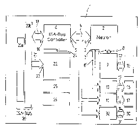
Fig. 1 shows an overview of the principle arrangement of the different
assemblies, respectively
components of the selection device l, which at present is made as a PC104
plugin card. The
control device 1 has a microprocessor 2, at present a Neuron 3150, which is
connected via an
interface 3 via a bus system 1 bidirectionally with the interface 5 of a bus
controller 6. The bus
system 4 here at present is a 12C bus. Further the microprocessor 2 has an
interface respectively
T, which for physical control of terminal devices is connected to a bus system
8, respectively 8',
at present an LON bus, respectively SPT bus, which is bidirectionally
connected with interface
assemblies 9 and 10, which for the direct physical connection of terminals
occasionally over lines
not shown here via corresponding bus systems 13 and analog signal lines 14
select different
interfaces 15,16, and 17. The bus controller 6 is connected with an bus system
connection 20 via
a bus system 19 bidirectionally, the bus system 19 and the bus system
connection 20 at present
being made as an ISA bus. The bus system connection 20 in this case includes
an AT bus 20a
and an XT bus 20b. _~rl address decoder 22 is connected to the bus system
connection 20 via a
bus system 21 via a corresponding interface 23. The address decoder 22 in this
case checks if
CA 02324750 2000-11-27
6
there is an addressing of the control device 1 responding to a control device
not shown here via
the bus system connection 20 and via the connection indicated as 24 in Fig. 1,
a so-called chip
select, activates the bus controller 6, so that the microprocessor 2 can
exchange data with the
control device via the bus system 4, the bus controller 6, and the bus system
19, which by the
microprocessor the interface assemblies 9 or 10 transfer via the bus system 8,
respectively 8', to
the bus systems 12, or analog signal lines 14, and the interfaces 15 or 17, to
the terminals for the
physical selection of the same, respectively via the bus system 4 and the
interface assemblies 11
and 32, to the bus systems 14 and 31, and to the interfaces 17 and 30.
Furthermore Fig. 1 shows
assemblies 25 and 26 which are used for addressing and setting the transfer
channels to the bus
systems 19, respectively 20.
Fig. 2 shows a part of the layout of the selection device 1 according to Fig.
1, different driver
stages and connection lines not being shown explicitly. As is shown in Fig. 2,
in the case of the
address decoder 22 it is a matter of an 8-bit comparator of type 74HCT588, it
being possible to
have an 8-bit address for the selection device 1, which in the case of a
corresponding addressing
by the ISA bus system 21 activates the chip select 24 of the ISA bus
controller 6, at the present
time of type PCF 8584T, via the assembly indicated as 25 in the case of a
corresponding setting,
so-called jumper position, and making possible a bidirectional data exchange
via the bus system
connection 20 ,by a control device not shown here, to the 12C bus 4, thus to
the microprocessor.
Fig. 3a and 3b show a further part of the layout of the selection device 1. In
this case the lines
indicated in Figs. 3a and 3b with V 1 and V2 are connected with one another.
Fig. 3b shows the
microprocessor 2, which is connected bidirectionally with the ISA bus
controller 6 via the 12C
bus system 4. The microprocessor 2, at present a Neuron 3150 of type MC143150
of the
Motorola Company is connected with the memory components 27 and 28 shown in
Fig. 3a via
the lines indicated as V 1. Here it is a matter of a RAM in the case of the
memory component 27
and in the case of the memory component a Flash EPROM. As is shown further in
Fig. 3b, the
microprocessor 2 is connected via different signal lines 8, at present an SPI
bus, a 12C bus and
N LON bus with different interface assemblies 9, 10, that is, l0a and lOb, 11
and 29, which
select the interfaces 15, 16, 17, and 30, which are provided for direct
physical selection of
.'. CA 02324750 2000-11-27
7
terminals, via the bins systems 12, 13, 14, and 31. In the case of the
interface assembly 9 it is a
matter of a so-called r ree Typology Transceiver that provides an LON bus via
the bus system 12
and the interface 16. In the case of the interface assembly 29, at present a
PCF8574AT is a
so-called I/O expander, which provides different digital inputs and outputs
via the bus system 31
and the interface 30. The interface assembly 10, a so-called Universal
Asynchron Receiver
Transmitter (UART), provides an RS232, respectively RS485 connection for
terminals via the
two interface components 1 Oa, at present a MAX-518, and l Ob, at present a
MAX-3100, via the
bus system 13 and the interface 16. In the case of the interface assembly 11
it is a matter of an
AD/DA converter, at present of the type AD7417BR, which makes possible a
connection of
terminals to the selection device 1 via the bus system 14 and the interface
17.
i
. CA 02324750 2000-11-27
8
Reference number list
1 control device
2 microprocessor
3 interface
4 bus system (12C bus)
S interface
6 bus controller
7 interface
8 bus system / signal lines
(LON bus)
8' bus system (SPI bus)
9 interface assembly
l0a interface assembly
lOb interface assembly
11 interface assembly/ADIDA
converter
1 12 bus system
S
13 serial interface
14 analog signal lines
interface
16 interface
17 interface
18 interface
19 bus system
20 bus system connection
20a AT bus
20b XT bus
21 bus system
22 address decoder
23 interface
24 chip select
25 assembly
i
'~ CA 02324750 2000-11-27
9
26 assembly
27 memory component
28 memory component
29 interface component
30 interface
31 digital signal lines
32 interface component /
digital I/O