Note: Descriptions are shown in the official language in which they were submitted.
CA 02325154 2000-11-03
- 1 -
This invention relates to apparatus for supplying liquid
from one level to a higher level. The invention is particularly
applicable for use in moving water from a lake or river, etc. ,
to a building, such as a house or cottage, which is at a higher
level than the lake or river.
To supply a house or cottage with water from a lake it
has been the practice to build a pump house beside the lake.
Often the pump itself is located in the lake and this can freeze
over in the winter. Furthermore, the pump can be pulled away by
ice in the lake or river. It is also extremely difficult to
remove the pump from the water if a fault occurs and maintenance
is required. There are thus several disadvantages in previous
systems.
On occasions a well is built near a house to supply water
for bath, showers and toilets, and, perhaps, drinking water.
This can be expensive and a disadvantage.
From one aspect of the invention it is an object to
provide a water supply system in which the above-mentioned
disadvantages are obviated or substantially reduced.
According to this aspect there is provided a supply
system for supplying water to a building at a higher level than
a lake comprising:-
a water supply pipe with one end in said lake and another
end connected to a closed container substantially full of water,
in use, and buried completely in the ground at a sufficient
depth so that the water does not freeze at that depth,
a water pump immersed in the water in said container with
an inlet to draw water from said container and pump it through
an outlet of said container,
a water supply pipe with one end connected to said outlet
and another end at said building to supply water thereto
wherein said inlet is an inlet pitless adapter and said
outlet is an outlet pitless adapter
CA 02325154 2000-11-03
- 2 -
Embodiments of the invention will now be described,
by way of example, with reference to the accompanying
drawings in which:-
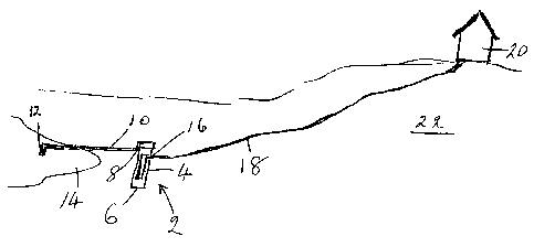
Figure 1 is a diagrammatic representation of a
water supply system;
Figure 2 is a diagrammatic representation of a
pumping assembly for use in the water supply system of
Figure 1, shown partly in a dissembled condition for ease
of description; and
Figures 3 and 4 diagrammatically illustrate another
water supply system.
Referring to Figure 1 a pump apparatus 2 containing
a pump 4 is installed with its lower end 6 below ground
level and buried in the ground with at least its base 6 at
a sufficient depth so that any water therein does not
freeze at that depth. This is normally referred to as
below the frost line. An inlet 8 to the pump assembly 2
has an inlet pipe 10 connected thereto. The other end of
the pipe 10 is provided with a screened inlet portion 12
which is immersed in the water in a lake 14.
The outlet 16 from the pump apparatus 2 is
connected to a further pipe 18 whose other end is within a
house 20. The house 20 is at a higher level on the hill
22 than the lake 14.
As will be appreciated, when the pump apparatus 2
is operational it can draw water from the lake 14 for
supply to the house 20 or other building.
In Figure 2 the pump apparatus 2 is
diagrammatically illustrated. Parts thereof are shown in
a dissembled condition for ease of the present description.
The pump apparatus 2 includes a container 24
enclosing the pump 4 which is of the submersible type.
The container 24 is of 6-inch diameter and at its lower
end the inlet 8 is at the end of a 6-inch by 1'/~ reducer
portion and is provided with a threaded brass poly insert
fitting for connection to the pipe 10 (Figure 1).
CA 02325154 2000-11-03
- 3 -
The outlet 16 is located in the side of the
container 22 and at the top of the container a female
adapter 26 is provided. A corresponding threaded cap 28
is also provided and this screws within the adapter 26,
sealing being achieved by way of a rubber gasket 30. An
auto air vent 32 is provided on top of the cap 28 and this
is designed to release air and not water from the
container 24.
The submersible pump 4 has a water intake opening
34 and the pump motor 36 is located below the water intake
34. The outlet from the pump 4 is through a reduced
outlet 36 having a pump foot valve 38 (small hole drilled
in nylon foot valve).
The outlet from the portion 36 is through a brass
nipple portion 40 and then through a pitless adapter 42
and a brass insert adapter 44.
The electrical wires 46 for the motor 36 enter the
container 24 through an airtight seal 48.
As shown in Figure 2 the water inlet for the
container 24 is by way of a threaded brass poly insert
fitting 50 connected to the water inlet portion 8.
In use, when the motor 36 is switched on then the
pump creates a vacuum in the container casing 24 and this
draws water from the lake 14 (Figure 1) . The water fills
up the container 24 so that the water level is
substantially at the top of the container casing. The
water is then pumped at high pressure to the house 20.
The small hole drilled in the foot valve 38 (a check
valve) allows a small amount to slowly return, thus
forcing any air trapped in the top of the pump casing to
escape out of the system.
The container 24 can be constructed of 5-inch or
larger diameter pipe made of PVC, styrene, metal, molded
fibre-glass or ABS.
CA 02325154 2000-11-03
- 4 -
The system works on the principle of the pump
creating a vacuum when it is running and sucking the water
from the lake, river, etc. via, for example, poly pipe
with a foot valve installed in the water.
The container 24 should be buried as close to water
level as possible to avoid reducing the head or pumping
height ability of the pump.
When the desired pressure is achieved in the house,
the pump shuts off. When this occurs the pressure and a
small amount of water returns slowly to the container 24
and forces any trapped air at the top of the pump housing
out via the automatic vent 32 which closes when the air is
vented.
The water can not return to the lake, etc. because
of the foot valve in the lake. If the entire pump housing
is kept free from air a hole in the pump check valve and
the auto vent are not required. These portions are added
so as to make the system more user friendly.
The water entering the bottom of the container
system is drawn over the pump motor, thus cooling the
motor. The pump housing and pipe to the lake must only be
filled once.
The length of the pump housing and the horsepower
(H.P.) of the pump would be determined by the
application. It will be understood that the housing could
be sold in lengths of 4-foot to 8-foot or more with the
pump installed in it in the majority of cases.
The model numbers would indicate the length of
casing and the horsepower of the pump.
For example:-
Model P.W. 4 33
Pumpwell 4 ft. 1/3 H.P.
Model P.W. 6 50
Pumpwe 11 6 f t . '/Z H . P .
Model P.W. 5 75
Pumpwe 11 5 f t . 3/~ H . P .
CA 02325154 2000-11-03
- 5 -
The advantages of a constructed pump well system
are as follows:-
(1) No need to dig a well and install well tile
where you may not find water.
(2) No need to drill a well which is extremely
expensive and no guarantee of water or
supply, or quality of water.
(3) No need to build a heated, insulated pump
house where a jet pump must be installed at
water source to have the ability to pump high
enough.
(4) No pump or wiring in water source.
(5) No need to ground fault system.
(6) Pump can be easily removed year round.
(7) Does not waste drinking water to flush
toilets, bath, etc.
(8) Many people even with drilled or dug wells
buy bottled drinking water.
(9) In most cases water can be purified for just
drinking supply in house (if needed).
(10) No need to drain pump system if not used in
winter.
(11) Soft water better for washing, watering
lawns, and gardens, etc.
(12) With extra return line to lake and bypass
valve in home pump could be let run
continuously for heating, cooling purposes.
(13) No noisy pump in house.
(14) Very cost effective and efficient as compared
to drilling etc.
(15) Just dig trench deeper where pump well to be
installed.
(16) Pump is needed in all but gravity fed systems
already so cost of pump not really a factor.
CA 02325154 2000-11-03
- 6 -
(17) No risk of pump freezing over in water
source, or removing dug well lid and getting
ladder to remove pump.
(18) No risk of running out of water or running
pump dry.
(19) In a case where there is an existing well
that is or is not adequate, the pump could
compliment the well system.
(20) Many water sources in Canada and United
States, especially, are drinkable or could be
with little treatment.
(21) Very little water really used for consumption
(seems a shame to waste good drinking water
to flush toilets, wash cars, water lawns, etc.
(22) No need for a pump house (heated or not).
(23) Pump can be removed easily (winter or summer).
(24) Pump will not freeze or be pulled away by ice
in river or lake.
(25) System does not have to be ground faulted.
(26) Pump can run continuously to keep lines from
freezing in shallow areas.
(27) In continuous operation returning water to
supply via water rads in home it would keep
the home constantly above freezing.
(28) No need to dig or drill a well ($1200.00 -
$6000.00 or more).
(29) All you need (outside of trenching for poly
pipe) is an auger or post hole digger to
install it.
(30) In continuous mode pipes could nearly lay on
ground surface.
(31) No hard priming of pump (fill casing once).
(32) No noisy pump in house.
(33) Very good for tourist camps that need a very
large amount of water for toilets and showers.
CA 02325154 2000-11-03
_ 7 _
(34) Need only a small area of over-burden to
install system.
(35) Many pump companies would be interested in
this system.
(36) Very good where you have a high head from
water source to home.
(37) Could help home cool in summer.
(38) Top can be flush with ground with Styrofoam
cover.
It will be understood that this system is
particularly advantageous in those areas where the lakes
or rivers freeze up and there is ice movement. With the
described embodiment it is not so difficult to examine the
pump if problems arise. Furthermore, the system can be
used year-round in cottage country so that the owner can
use the cottage at different times of the year.
It will be appreciated that the pump apparatus and
pump system may be used with other liquids than water.
For example, a large container of fuel oil may be located
at the bottom of a hill and conveniently pumped to a house
at the top of the hill by means of the described
embodiment. It could also be used for wine or maple syrup.
The pump apparatus may, of course, be used when it
is at the same level as the source of liquid and the
destination thereof.
The system may sometimes be referred to as a
portable well system.
A further improvement is illustrated in Figures 3
and 4.
The buried inground system comprises a housing or
container 60 constructed of metal pipe, P.V.C., fiber
glass or other material which has been constructed in such
a manner as to make it airtight.
CA 02325154 2000-11-03
_ g _
The inside diameter of container 60 is 5 inches
which I have found to be the minimum advisable. The
length of the entire housing was dependent on the frost
condition in the area in which it was used and was
normally between 4 and 6 feet.
The container 60 houses a submersible pump 62
(without a check valve) and this is mounted on a pitless
adapter 64 for easy removal. A check valve 66 is mounted
on the pitless adapter 64 and this operates as an inlet
for the system and avoids the need for a footvalve in lake
68. The ground level is identified as 69.
A three-quarter inch hole 70 drilled into the drop
pipe portion of the pitless adapter 64 allows the water
from. The home 72 and poly pipe outlet line 74 to return
back through the pump 62 and a check valve 76 at the top
of a return drain stand pipe 78 within the pumpwell casing
60 and then through the pitless adapter 64.
When the pump shuts off, this causes the outlet
polyline 74 to the house 72 to be emptied so that it
cannot freeze. A schrader valve or two check valves 80
and 82 in the home 72 will still keep pressure in the home
and pressure system.
The outlet of a pressure tank 83 is provided with a
pressure switch 85.
As will be appreciated an advantage of the system
shown in figures 3 and 4 is that when it is set up to self
drain the lines, any screen or filter 84 on the end of the
polypipe 86 in the lake will be backwashed by the water
returning to the lake 68.
Since the entire pump system is buried completely
underground, it does not freeze.
In use, the system is first filled with water and
then capped by a bolted cap 88 fitting on a welded flange
CA 02325154 2000-11-03
_ g _
with gasket therebetween. A threaded 1 inch nipple is
provided on a filler cap 92 whilst the outlet 94 to
polypipe line 74 is shown in figure 4. A pitless adapter
is provided for outlet 94.
It will be appreciated that a pitless adapter
permits removal of a pump without having to undo any
connections. The pump portion of the adapter slides into
a support section and is sealed with an O-ring. The
pitless adapter supports the submersible pump in a drilled
well casing, a 1 3/4 inch hole being bored or cut in the
casing. The pitless adapter is sealed with rubber washers
inside and outside of the well casing and secured with a
brass nut.
Once capped and full of water, the pump 62 is
switched on and draws water from the lake through pipe 86
to a level 87. A float switch 96 is provided and this
operates to shut off the pump 62 to prevent it from
running dry. It is connected in the wiring 98 to pump 62.
If the supply pipe 74 to the home 72 can be buried
deep enough to prevent freezing whereby the pipe does not
have to be emptied, a threaded plug is installed in the
return check valve 76. Due to the height of the stand
pipe 78 and reverse check valve 76, the water in the pump
system is only able to drop to a certain level which is
still well above the pumps intake.
When the system is first installed, it is initially
filled with water. The bolted cap 88 is placed on the
pumpwell casing container 60 and tightened. The pump 62
is then run for a short time and, after this, the small
filler cap 92 is removed and the pump system is filled
again. The pump 62 is then run again. This is repeated
until no air is left escaping from the filler cap 92.
Once primed, the container 60 is completely buried below
the frost line and should, in normal circumstances, never
have to be drained or primed again.
CA 02325154 2000-11-03
- 10 -
No foot valve is provided in the lake in the system
of figures 3 and 4 and this is a considerable advantage.
Since the rest of the system can be drained, it
will be of special interest to people living by the lake,
or other water source, where ground conditions may not
permit the supply pipe to the home to be buried at a
sufficient depth to prevent freezing.
Advantages of the system are:
1. No well drilling
2. No well digging
3. No pump or tripod in lake
4. No pump house
5. No pump installation
6. No ground faulting electrically
7. No winter draining
8. No priming
9. Self-drain supply line
10. No Freezing
11. Able to pump long distances and extreme heights
12. Easy pump and foot valve access year round
13. Very easy installation
14. Environmentally friendly (no metal in lake)
15. Will backwash and clean screen or filter intake
It will be readily apparent to a person skilled in
the art that a number of variations and modifications can
be made without departing from the true spirit of the
invention which will now be pointed out in the appended
claims.