Language selection

Search

Patent 2325407 Summary

Third-party information liability

Some of the information on this Web page has been provided by external sources. The Government of Canada is not responsible for the accuracy, reliability or currency of the information supplied by external sources. Users wishing to rely upon this information should consult directly with the source of the information. Content provided by external sources is not subject to official languages, privacy and accessibility requirements.

Claims and Abstract availability

Any discrepancies in the text and image of the Claims and Abstract are due to differing posting times. Text of the Claims and Abstract are posted:

  • At the time the application is open to public inspection;
  • At the time of issue of the patent (grant).
(12) Patent Application: (11) CA 2325407
(54) English Title: REEL FOR A THIN METAL STRIP
(54) French Title: BOBINEUSE POUR UNE BANDE METALLIQUE MINCE
Status: Deemed Abandoned and Beyond the Period of Reinstatement - Pending Response to Notice of Disregarded Communication
Bibliographic Data
(51) International Patent Classification (IPC):
  • B21C 47/06 (2006.01)
(72) Inventors :
  • LADDA, DIETER (Germany)
  • IRLE, REINHARD (Germany)
  • BRAUN, MARTIN (Germany)
(73) Owners :
  • SMS SCHLOEMANN-SIEMAG AKTIENGESELLSCHAFT
(71) Applicants :
  • SMS SCHLOEMANN-SIEMAG AKTIENGESELLSCHAFT (Germany)
(74) Agent: RICHES, MCKENZIE & HERBERT LLP
(74) Associate agent:
(45) Issued:
(86) PCT Filing Date: 1999-03-20
(87) Open to Public Inspection: 1999-09-30
Examination requested: 2004-03-02
Availability of licence: N/A
Dedicated to the Public: N/A
(25) Language of filing: English

Patent Cooperation Treaty (PCT): Yes
(86) PCT Filing Number: PCT/EP1999/001885
(87) International Publication Number: WO 1999048629
(85) National Entry: 2000-09-21

(30) Application Priority Data:
Application No. Country/Territory Date
198 12 620.4 (Germany) 1998-03-23

Abstracts

English Abstract


The invention relates to a winder for a thin metal strip (1) comprising a
winder mandrel (2), a feeding element (3) for tangentially feeding the metal
strip (1) to the winder mandrel (2), and at least six pressure rollers (7)
with pressure roller axles (8) for guiding the metal strip (1) around the
winder mandrel (2). The pressure rollers (7) are arranged around the winder
mandrel (2), are lodged in the tightening elements (4), and can be tightened
against the winder mandrel (2) by means of tightening drives (6).


French Abstract

L'invention concerne une bobineuse pour une bande métallique mince (1), comportant un mandrin (2), un élément d'acheminement (3) pour acheminer tangentiellement la bande métallique (1) vers le mandrin (2), et au moins six rouleaux presseurs (7) comportant des axes (8) pour guider la bande métallique (1) autour du mandrin (2). Les rouleaux presseurs (7) sont placés autour du mandrin (2), logés dans des éléments de serrage (4) et peuvent être serrés contre le mandrin (2) au moyen d'éléments de commande de serrage (6).

Claims

Note: Claims are shown in the official language in which they were submitted.

claims
1. Reel for a thin metal strip (1). with a reel mandrel (2), a feed
element (3) for the tangential feed of the metal strip (1) to the reel
mandrel (2) and cat least six pressure rollers (7) with pressure roller
axles (8) for guiding the metal strip (1) round the reel mandrel (2),
whereby the pressure rollers (7) are located round the reel mandrel
(2), mounted in adjusting elements (4) and adjustable to the reel
mandrel (2) by means of adjusting drives (6).
2. Reel according to claim 1,
characterized in that
at least two pressure rollers (7) are mounted in each of the
adjusfing elements (4).
3. Reel according to claim 2,
characterized in that
the adjusting elements (4) are pivotable at pressure rollers (7)
adjusted to the reel mandrel (2) round pivot axes parallel to the
pressure roller axles (8).
7

4. Reel according to claim 1, claim 2 or claim 3.
characterized in that
a separate rotary drive (9) is assigned to each of the adjusting
elements (4) for the pressure rollers (7) mounted in this adjusting
element (4).
5. Reel according to claim 2, claim 3 or claim 4,
characterized in that
the number of adjusting elements (4) is three or four.
6. Reel according to one of claims 1 through 5,
characterized in that
guide plates (10) for guiding the metal slip (1) from one of the
pressure rollers (7) to the next of the pressure rollers (7) are located
between the pressure rollers (7).
7. Reel according to one of claims 1 through 6,
characterized in that
fihe adjusting drives (6) are configured as power-controlled and
position-controlled adjusfing drives (6).
8. Reel according to one of claims 1 through 7,
characterized in that
the adjusting drives (6) are configured as hydraulic cylinder units.

Description

Note: Descriptions are shown in the official language in which they were submitted.


CA 02325407 2000-09-21
Reel for a thin metal strip
The present invention relates to a reel for a thin metal strip, with a reel
mandrel, a feed element for feeding the metal sfiip to the reel mandrel
and pressure rollers with pressure roller axles for guiding tha metal ship
round the reel mandrel, whereby the pressure rollers are located round
the reel mandrel, mounted in adjusting elements and adjustable to the
reel mandrel by means of adjusting drives.
Such reels are known. As a rule they have three, sometimes also four,
pressure rollers between which guide plates are located.
When start-winding a strip, I,e. when winding the first one or two
i o windings, the strip is transferred onto the reel mandrel in transfer
operation. In the case of thin strips with a thickness of less than 3 mm.
partially of less than 1 mm, the strip ls, however, very unstable In transfer
operation - in particular at high strip speeds. On account of the friction
at the guide plates, It fends. to bulge or to warp, so that proper start
15 winding is hardly possible any more in these cases. The problem of a
blocking of the winding procedure is even greater if thin strips are
wound at a high strip speed, The strip speed is ca. 15 m/s; for future
systems, even 20 m js are planned, The centrifugal force occurring
during fihe formation of the first windings is thus very high.

CA 02325407 2000-09-21
The object of the present invention consists in providing a reel with
which the start-winding of thin strips - in parflcular also at a high start
winding speed - Is readily and reliably possible.
The object is solved in that the feed element feeds the metal strip
s tangentially to the reel mandrel and that at least 6 pressure rollers are
located round the reel mandrel,
On account of the tangential feed, the strip start is Inserted relidbiy
between the first pressure roller and the reel mandrel. On account of
the provision of at least six pressure rollers, only a substantially smaller
1 o angle has to be bridged until the next pressure roller. The metal sfiip
must thus be freely transferred only over very short distances before It is
taken over by the next pressure roller.
The structural design of the reel is especially simple If at least two
pressure rollers are mounted in each of the adjusting elements.
~ s if a separate rotary drive is assigned to each of the adjusting elements
for the pressure rollers mounted in this adjusting element, a uniform
speed and thus also peripheral speed of the pressure rollers mounted In
this adjusting element is guaranteed by especially simple means.
The number of adjusfing elements Is preferably three or four.
2o If guide plates for guiding the metal strip from one of the pressure
toilers
to the next of the pressure rollers are located between the pressure
rollers, the metal strip is guided even more dependably round the reel
mandrel.
The adjusting drives care preferably configured as power-controlled and
posffion-controlled drives, e.g, as pressure-controlled and position-
contro(led hydraulic cylinder units,
2

CA 02325407 2000-09-21
If the reel mandrel has an ad)ustable reel mandrel diameter, by
increasing the reel mandrel diameter after the winding of the first
windings, the then wound-on metal strip can be taken over by the reel
mandrel by simple means.
s Further advantages and details are to be gathered from the following
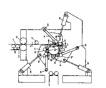
description of an embodiment. Thereby the only
figure shows a side view of a reel
in schematic representation.
Wfifi the reel represented in the figure, a thin steel strip 1 with a
thickness
1 o d is to be wound onto a reel mandrel 2. The thickness d of the steel strip
1 is not more than 3 mm, in the embodiment 1 mm. The reel mandrel 2
has a diameter D. The diameter D of fihe reel mandrel 2 Is ad)ustable. At
the beginning of the winding-on of the steel strip l, the reel mandrel 2 is
set to a diameter D between its minimum value and Its maximum value.
i s For guiding the steel strip 1 to the reel mandrel 2. the reel has o feed
element 3. According to the embodiment, the feed element 3 is
configured as a roller table 3 and located in such a way that It
transports the steel strip 1 horizontally in such a way that the steel strip 1
Is fed tangentially to fihe reel mandrel 2. A strip driver 3' can be assigned
2 o If applicable to the roller table 3,
For guiding the steel strip 1 round the reel mandrel 2, the reel has three
ad)usting elements 4 which are located substantially uniformly round the
reel mandrel 2. The ad)usting elements 4 are mounted in pivot bearings
and ad)ustable to the reel mandrel 2 by me4ns of the adJusting drives
2 s 6. According to the embodiment. the adjusting drives 6 are configured
as pressure-controlled and position-controlled hydraulic cylinder units.
For this purpose, the adjusting . drives 6 have position transducers and
pressure sensors (not shown), These are activated by means of a servo
3

CA 02325407 2000-09-21
control (also not shown).
Three pressure rollers 7 with pressure roller axles 8 are mounfed in each
of the adjusting elements 4. Through acfivation of the adjusting drives b,
the adjusting elements 4 and thus also the pressure rollers 7 can thus be
s adjusted to the reel mandrel 2.
The pressure rollers 7 are driven. For this purpose a separate rotary drive
9 Is assigned to each adjusting element 4, by means of which rotary
drive the pressure rollers 7 mounted in This adjusting element 4 Are
driven. The frontmost of the pressure rollers 7 of each adjusting element
4 is thereby driven indirectly via the central one of the pressure rollers 7
of the respective ad)usting element 4 and an intermediafie gearwheel
9.
The guiding performance induced by the pressure rollers 7 c4n be even
further optimized if the adjusting elements 4 are plvotable at pres9ure
i s rollers adjusted to the reel mandrel 2 round the pressure roller axle 8 of
their respectively frontmost pressure roller 7 or a pivot axis located in
their vicinity.
In order to improve the guiding performance for the steel strip 1 round
the reel mandrel 2 even further, guide plates 10 are located between
2o neighboring pressure rollers 7. On account of the only small angles to be
bridged from one pressure roller 7 to the next pressure roller 7, the
friction between the steel strip 1 and the respective guide piste 10 is so
small that there is no risk of breakdowns.
At fihe beginning of the start-winding, the pressure rollers 7 are located
2 s at a distance from the reel mandrel 2, so that the steel strip 1 can be
inserted befiween the pressure rollers 7 and the reel mandrel 2. Altar the
forming of the first winding, the diamefer D of fihe reel mandrel 2 is
increased and simultaneously the pressure rollers 7 ate adjusted
completely to the reel mandrel 2, After a strip tension has built up in the
4

CA 02325407 2000-09-21
steel strip 1, the adjusting elements 4 are then pivoted away from the
reel mandrel 2 and the steel strip 1 is wound on.
if the diameter of the wound-on steel strip 1 in increased gradually, said
steel strip triggers a guiding and belfi tension measuring roller 11 by
s means of which roller the steel strip 1 is guldable and by means of which
strip a strip tension component can be measured by means of
pressductors.
According to the above embodiment, three adJusfing elements 4, each
with three pressure rollers 7, are provided. However, an embodiment
~",ith only two pressure rollers 7 per ad)usiing element Q Is also adequate.
'this applies In particular if four adjusting elemenfis 4, each with two
pressure rollers 7, dre used instead of the three adjusting elements 4.
The reel according to the invention can be used optionally for the
winding-on of hot strip or cold sfirip.
5

CA 02325407 2000-09-21
List of roferenco numbers
1 Metal strip/steel strip
2 Reel mandrel
3 Feed element
3' Strip driver
4 Adjusting elements
Pfvot bearings
b Adjusting drives
7 Pressure rollers
8 Pressure roller vales
9 Rotary drives
9' intermediate gearwheels
Guide plates
11 Guiding and strip tension mevsurfng
roller
d Thickness
D Diameter

Representative Drawing
A single figure which represents the drawing illustrating the invention.
Administrative Status

2024-08-01:As part of the Next Generation Patents (NGP) transition, the Canadian Patents Database (CPD) now contains a more detailed Event History, which replicates the Event Log of our new back-office solution.

Please note that "Inactive:" events refers to events no longer in use in our new back-office solution.

For a clearer understanding of the status of the application/patent presented on this page, the site Disclaimer , as well as the definitions for Patent , Event History , Maintenance Fee  and Payment History  should be consulted.

Event History

Description Date
Application Not Reinstated by Deadline 2006-03-20
Time Limit for Reversal Expired 2006-03-20
Deemed Abandoned - Failure to Respond to Maintenance Fee Notice 2005-03-21
Amendment Received - Voluntary Amendment 2004-06-25
Appointment of Agent Requirements Determined Compliant 2004-03-23
Revocation of Agent Requirements Determined Compliant 2004-03-23
Inactive: Office letter 2004-03-23
Letter Sent 2004-03-23
All Requirements for Examination Determined Compliant 2004-03-02
Request for Examination Received 2004-03-02
Request for Examination Requirements Determined Compliant 2004-03-02
Revocation of Agent Request 2004-02-20
Appointment of Agent Request 2004-02-20
Letter Sent 2001-04-05
Inactive: Single transfer 2001-03-12
Inactive: Cover page published 2001-01-10
Inactive: First IPC assigned 2001-01-07
Inactive: Courtesy letter - Evidence 2000-12-27
Inactive: Notice - National entry - No RFE 2000-12-21
Application Received - PCT 2000-12-15
Application Published (Open to Public Inspection) 1999-09-30

Abandonment History

Abandonment Date Reason Reinstatement Date
2005-03-21

Maintenance Fee

The last payment was received on 2004-02-18

Note : If the full payment has not been received on or before the date indicated, a further fee may be required which may be one of the following

  • the reinstatement fee;
  • the late payment fee; or
  • additional fee to reverse deemed expiry.

Please refer to the CIPO Patent Fees web page to see all current fee amounts.

Fee History

Fee Type Anniversary Year Due Date Paid Date
Basic national fee - standard 2000-09-21
MF (application, 2nd anniv.) - standard 02 2001-03-20 2001-02-21
Registration of a document 2001-03-12
MF (application, 3rd anniv.) - standard 03 2002-03-20 2002-02-21
MF (application, 4th anniv.) - standard 04 2003-03-20 2003-02-14
MF (application, 5th anniv.) - standard 05 2004-03-22 2004-02-18
Request for examination - standard 2004-03-02
Owners on Record

Note: Records showing the ownership history in alphabetical order.

Current Owners on Record
SMS SCHLOEMANN-SIEMAG AKTIENGESELLSCHAFT
Past Owners on Record
DIETER LADDA
MARTIN BRAUN
REINHARD IRLE
Past Owners that do not appear in the "Owners on Record" listing will appear in other documentation within the application.
Documents

To view selected files, please enter reCAPTCHA code :


To view images, click a link in the Document Description column. To download the documents, select one or more checkboxes in the first column and then click the "Download Selected in PDF format (Zip Archive)" or the "Download Selected as Single PDF" button.

List of published and non-published patent-specific documents on the CPD .

If you have any difficulty accessing content, you can call the Client Service Centre at 1-866-997-1936 or send them an e-mail at CIPO Client Service Centre.


Document
Description 
Date
(yyyy-mm-dd) 
Number of pages   Size of Image (KB) 
Representative drawing 2001-01-10 1 10
Cover Page 2001-01-10 1 43
Description 2000-09-21 6 218
Abstract 2000-09-21 1 61
Drawings 2000-09-21 1 17
Claims 2000-09-21 2 49
Reminder of maintenance fee due 2000-12-19 1 112
Notice of National Entry 2000-12-21 1 195
Courtesy - Certificate of registration (related document(s)) 2001-04-05 1 113
Reminder - Request for Examination 2003-11-24 1 123
Acknowledgement of Request for Examination 2004-03-23 1 176
Courtesy - Abandonment Letter (Maintenance Fee) 2005-05-16 1 174
Correspondence 2000-12-21 1 14
PCT 2000-09-21 15 505
Correspondence 2004-02-20 2 85
Correspondence 2004-03-23 1 15
Correspondence 2004-03-23 1 18