Language selection

Search

Patent 2325495 Summary

Third-party information liability

Some of the information on this Web page has been provided by external sources. The Government of Canada is not responsible for the accuracy, reliability or currency of the information supplied by external sources. Users wishing to rely upon this information should consult directly with the source of the information. Content provided by external sources is not subject to official languages, privacy and accessibility requirements.

Claims and Abstract availability

Any discrepancies in the text and image of the Claims and Abstract are due to differing posting times. Text of the Claims and Abstract are posted:

  • At the time the application is open to public inspection;
  • At the time of issue of the patent (grant).
(12) Patent Application: (11) CA 2325495
(54) English Title: METHOD AND DEVICE FOR WIDE-ANGLE PROJECTION
(54) French Title: PROCEDE ET DISPOSITIF POUR PROJECTION GRAND ANGLE
Status: Deemed Abandoned and Beyond the Period of Reinstatement - Pending Response to Notice of Disregarded Communication
Bibliographic Data
(51) International Patent Classification (IPC):
  • G03B 21/00 (2006.01)
  • G03B 21/28 (2006.01)
  • G03B 21/56 (2006.01)
(72) Inventors :
  • MAYR, PETER (Germany)
(73) Owners :
  • DATAFRAME VERTRIEB AUDIOVISUELLER KOMMUNIKATIONSSYSTEME GMBH
(71) Applicants :
  • DATAFRAME VERTRIEB AUDIOVISUELLER KOMMUNIKATIONSSYSTEME GMBH (Germany)
(74) Agent: OSLER, HOSKIN & HARCOURT LLP
(74) Associate agent:
(45) Issued:
(86) PCT Filing Date: 1999-02-11
(87) Open to Public Inspection: 1999-08-19
Availability of licence: N/A
Dedicated to the Public: N/A
(25) Language of filing: English

Patent Cooperation Treaty (PCT): Yes
(86) PCT Filing Number: PCT/EP1999/000897
(87) International Publication Number: WO 1999041641
(85) National Entry: 2000-09-22

(30) Application Priority Data:
Application No. Country/Territory Date
198 05 507.2 (Germany) 1998-02-11

Abstracts

English Abstract


The invention relates to a method for highly accurate wide-angle projection,
according to which a light cone emanating from a projector is diverted by a
convex, spherical mirror onto an essentially concave screen. The method is
carried out by means of a device for wide-angle projection, comprising at
least one projector (24), in front of whose lens (28) a mirror (22) with a
spherically convex mirror surface (32) is arranged. The mirror surface (32)
faces an essentially spherically concave screen (20).


French Abstract

L'invention concerne un procédé selon lequel, pour permettre une projection grand angle très précise, un cône lumineux sortant d'un projecteur est dévié, par un miroir sphérique convexe, sur un écran sensiblement concave. Ce procédé est mis en oeuvre avec un dispositif pour projection grand angle qui comporte au moins un projecteur (24) devant l'objectif (28) duquel est placé un miroir (22) comportant une surface réfléchissante (32) sphérique, convexe qui fait face à un écran (20) sensiblement sphérique, concave.

Claims

Note: Claims are shown in the official language in which they were submitted.

CLAIMS:
1. Device for wide-angle projection comprising at least one projector (24), in
front of
whose lens (28) a mirror (22) with a spherically convex mirror surface (32) is
arranged, the
minor surface (32) facing a substantially spherically concave screen (20),
characterized in
that the centers of curvature (K a; K S; K L)of the mirror surface (32) and of
the screen (20)
are in agreement or very close to each other.
2. Device for wide-angle projection in accordance with Claim 1, characterized
in that the
projector (24) is arranged in such a way that it is invisible for a person
observing the screen
(20).
3. Device for wide-angle projection in accordance with Claim 1, characterized
in that a
light valve projector is used as the projector (24).
4. Device for tower simulation purposes, comprising
- a centrally located tower imitation (12),
- several projectors (24) comprising lenses (28), which are arranged around
the tower
imitation (12) at an even angular distance, the lenses (28) facing the tower
imitation
(12),
- several minors (22), which are arranged around the tower imitation (12) at
an even
angular distance and are arranged, respectively, in front of the lens (28) of
a projector
(24) and which are equipped with a spherically convex mirror surface (32)
facing away
from the tower imitation (12), and
- a spherically concave screen (20) surrounding the tower imitation (12), the
projectors
(24) and the mirrors (22).
5. Device in accordance with Claim 4, characterized by the fact that the
centers of
curvature (K a; K S; K L) of the mirror surface (32) and of the screen (20)
are in agreement.

Description

Note: Descriptions are shown in the official language in which they were submitted.


CA 02325495 2000-09-22
-:L-
Method and Device for Wide-Angle Projection
The invention relates to a method and a device for wide-angle projection,
which can be used
especially for simulation purposes of a tower at an airport.
From the state of the art the usage of projectors with fisheye lenses is
known, with which light
emanating from the projector is widened, for wide-angle projection purposes.
The manufacturing
of these fisheye lenses, however, is very complex and requires the utmost
precision. Beyond that,
the usage of fisheye lenses leads to considerable loss of light due to the
lens system.
The invention is based on the task of creating with simple design means a
method and a device that
enable wide-angle projection with little loss of luminous intensity.
This task is solved with a method wherein a light cone emanating from a
projector is diverted onto
a screen of concave spherical design by a mirror of convex spherical design.
The task is also resolved with a device for wide-angle projection that
comprises at least one
projector in front of whose lens a mirror with a spherically convex mirror
surface is arranged, with
the mirror surface facing a substantially spherically concave screen.
The spherically concave mirror enables extreme widening of the light cone,
thus effecting an
enormous image size at a small distance from the projector with little loss of
luminous intensity.
The best image quality is achieved when the centers of curvature of the mirror
surface and of the
screen are in agreement or are close to each other.
Possibly occurring image distortions on the screen can be compensated with an
appropriate screen
shape or image pre-distortion.
Computer-controlled light valve projectors are preferably used as the
projectors.
An embodiment of the invention is explained more in detail in the following
with the drawings.
They show:

CA 02325495 2000-09-22
-2-
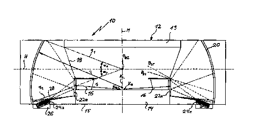
Fig. 1 cross-sectional view of a device for wide-angle projection that serves
the simulation of an
a<rport tower;
Fig. 2top view onto the device ofFig. 1;
Fig. 3 front view of a mirror used in the device of Fig. 1;
Fig. 4 section II-II of Fig. 3;
Fig. 5 section III-III of Fig. 3.
The device 10 for wide-angle projection depicted in Fig. 1 and 2 simulates the
environment of an
airport tower and serves the training of air traffic controllers. The device
10 comprises an imitation
of a tower 1 Z, whose cross-sectional contour (Fig. 2) has the shape of an
even octagon.
The tower imitation 12 is equipped with a base 14 that is arranged on a floor
15, with the surface of
the base forming a platform on which control panels 16 are arranged along its
circumference.
Adjacent to the upper edge of the control panels 16 the tower imitation 12 is
equipped with a
window area 18 that expands outward in a conical shape, which is adjacent to a
horizontally
arranged ceiling 19. The tower imitation 12 is surrounded by a screen 20 that
is arranged in a
coaxial manner to the tower imitation 12, has a spherically concave design and
extends from the
floor 15 of the device 10 up to the height of the upper surface of the ceiling
19.
A mirror 22a through 22e, respectively, is fastened centrally on each surface
section of the contour
of the tower imitation 12, adjacent downward to the window area 18. Each
mirror 22a through
22e is equipped with a spherically convex mirror surface 32 (fig 4, fig. S) on
the side facing the
screen 20. A projector 24a through 24e, respectively, is arranged in the floor
15 between each
mirror 22a through 22e and the screen 20 in a recess 26 that is adjacent to
the screen 20. Each
projector 24a through 24e is equipped with a lens 28 that is directed
diagonally upward towards the
center axis M onto the respective mirror 22a through 22e.
For the design of the device 10, a reference point of vision Bsz was used,
which is located on the
center axis M of the tower imitation at a height between a point of vision BsT
of a person standing
at a control panel 16 and a point of vision Bs~ of a person sitting at the
control panel. The height of
the screen 20 and its distance to the reference point of vision Bnz are
selected in such a way that the
screen extends between two straight lines gi and g2, with the straight Gne g~
extending upward
starting from the reference point of vision Bez at an angle al to the
horizontal H extending through
the reference point of vision BBZ. The straight line g2 extends downward
starting from the
reference point of vision Bsz at an angle a2 to the horizontal H. The angles
a1 and a2 preferably
each are 20°.

CA 02325495 2000-09-22
-3-
The distance of a projector 24 from the appropriate mirror 22 is selected in
such a way that each
mirror 22 can divert the fiall light cone of a projector 24 onto the screen 20
in such a way that the
light cones diverted by two neighboring mirrors 22 onto the screen 20
intersect only in a small area
(Fig. 2) on the screen 20.
The best image results are achieved when the centers of curvature K, through
IC~ of the mirrors 22a
through 22e are located very close to the center of curvature IG. of the
screen 20, which is located
on the center axis M, as shown in Fig. 1. Ideally, the centers of curvature K,
through I4 are in
agreement with the center of curvature ICi..
The projectors 24a through 24e are arranged in such a way that they cannot be
seen from the
points of vision Bsr and Bsi so that a person on the control panel 16 has a
clear view of the screen
20.
The individual projectors 24a through 24e are controlled by a computer in such
a way that they
generate a simulated full picture on the screen 20, which corresponds to a
360° view from an
airport tower.
In a preferred version of the device for wide-angle projection, the center of
curvature K,,, of the
screen 20 and the centers of curvature K, through K~ of the mirrors 22a
through 22e are in
agreement. The radius of curvature rs of the mirrors is approximately 3.34 m.
The radius of
curvature rr. of the screen is approximately 6.45 m.
The screen 20 is made, for example, of fire-retardant glass fiber plastic and
has a matte white
coating.
The design of the mirror 22 is shown more closely in Figs. 3 through 5. The
mirror 22 is formed by
a spherical segment with rectangular contour (Fig. 3). It consists preferably
of polished aluminum
on the nurror surface 32, which has been coated with chrome. It is also
possible, however, to use
mirrors with a beveled glass surface. Another possibility is a Mylar film that
has been tightened on
a round frame and is arched outward with air pressure in order to obtain the
convex shape.
The described device for wide-angle projection allows the depiction of
geometry onto the screen
with an exactness of down to 10 arc minutes. The mirrors 22a through 22e cause
an extreme
expansion of the light cone. The loss of light due to the mirrors 22a through
22e amounts to only
about 10%.

Representative Drawing
A single figure which represents the drawing illustrating the invention.
Administrative Status

2024-08-01:As part of the Next Generation Patents (NGP) transition, the Canadian Patents Database (CPD) now contains a more detailed Event History, which replicates the Event Log of our new back-office solution.

Please note that "Inactive:" events refers to events no longer in use in our new back-office solution.

For a clearer understanding of the status of the application/patent presented on this page, the site Disclaimer , as well as the definitions for Patent , Event History , Maintenance Fee  and Payment History  should be consulted.

Event History

Description Date
Inactive: Agents merged 2013-10-29
Inactive: IPC from MCD 2006-03-12
Application Not Reinstated by Deadline 2004-02-11
Time Limit for Reversal Expired 2004-02-11
Deemed Abandoned - Failure to Respond to Maintenance Fee Notice 2003-02-11
Letter Sent 2001-02-02
Inactive: Single transfer 2001-01-11
Inactive: Cover page published 2000-12-29
Inactive: First IPC assigned 2000-12-21
Inactive: Courtesy letter - Evidence 2000-12-19
Inactive: Notice - National entry - No RFE 2000-12-18
Application Received - PCT 2000-12-16
Application Published (Open to Public Inspection) 1999-08-19

Abandonment History

Abandonment Date Reason Reinstatement Date
2003-02-11

Maintenance Fee

The last payment was received on 2002-01-31

Note : If the full payment has not been received on or before the date indicated, a further fee may be required which may be one of the following

  • the reinstatement fee;
  • the late payment fee; or
  • additional fee to reverse deemed expiry.

Please refer to the CIPO Patent Fees web page to see all current fee amounts.

Fee History

Fee Type Anniversary Year Due Date Paid Date
Basic national fee - small 2000-09-22
Reinstatement (national entry) 2000-09-22
Registration of a document 2001-01-11
MF (application, 2nd anniv.) - small 02 2001-02-12 2001-02-08
MF (application, 3rd anniv.) - small 03 2002-02-11 2002-01-31
Owners on Record

Note: Records showing the ownership history in alphabetical order.

Current Owners on Record
DATAFRAME VERTRIEB AUDIOVISUELLER KOMMUNIKATIONSSYSTEME GMBH
Past Owners on Record
PETER MAYR
Past Owners that do not appear in the "Owners on Record" listing will appear in other documentation within the application.
Documents

To view selected files, please enter reCAPTCHA code :


To view images, click a link in the Document Description column. To download the documents, select one or more checkboxes in the first column and then click the "Download Selected in PDF format (Zip Archive)" or the "Download Selected as Single PDF" button.

List of published and non-published patent-specific documents on the CPD .

If you have any difficulty accessing content, you can call the Client Service Centre at 1-866-997-1936 or send them an e-mail at CIPO Client Service Centre.


Document
Description 
Date
(yyyy-mm-dd) 
Number of pages   Size of Image (KB) 
Representative drawing 2000-12-29 1 12
Abstract 2000-09-22 1 53
Description 2000-09-22 3 156
Claims 2000-09-22 1 40
Drawings 2000-09-22 3 60
Cover Page 2000-12-29 1 46
Reminder of maintenance fee due 2000-12-18 1 112
Notice of National Entry 2000-12-18 1 195
Courtesy - Certificate of registration (related document(s)) 2001-02-02 1 113
Courtesy - Abandonment Letter (Maintenance Fee) 2003-03-11 1 179
Reminder - Request for Examination 2003-10-15 1 112
Correspondence 2000-12-18 1 15
PCT 2000-09-22 9 277
Fees 2002-01-31 1 58
Fees 2001-02-08 1 63