Note: Descriptions are shown in the official language in which they were submitted.
' CA 02325537 2000-09-22
Process for Continuously Casting a Thin Strip as well
as Arrangement for Carrying out the Process
The invention relates to a process for continuously
casting a thin strip, in particular a steel strip,
preferably having a thickness of less than 10 mm, in a
two-roll process, wherein metal melt is cast into a
casting gap formed by two casting rolls in the
thickness of the strip to be cast while forming a melt
bath and the surfaces of the casting rolls above the
melt bath are swept with an inert gas or an inert gas
mixture as a function of the condition of the surfaces
of the casting rolls, as well as to an arrangement for
carrying out the process.
When casting a thin strip in the two-roll process, the
cross section of the strip is determined by the section
of the casting rolls in the hot state . It is essential
that the hot section exactly corresponds to the desired
strip cross section, since the strip section can no
longer be changed after the casting process, i.e. not
even by means of a rolling process . The hot section of
the casting rolls deviates considerably from the cold
section due to the periodically occurring very high
thermal loads exerted on the surfaces of the casting
rolls. Thermal cambering will be caused, which,
however, may be compensated for at least partially by
concave rough-grinding of the casting rolls.
Since the thermal load exerted on the casting rolls in
the casting process is, however, influenced by a
plurality of parameters and, in addition, a strip
caster should encompass a wide operating range (e.g. a
casting speed range between 0.2 and 2.5 m/s, a strip
thickness range between 1 and 10 mm, different rolling
forces occurring on the casting rolls, different
temperatures of the metal melt to be cast, different
melt quantities such as, e.g., different steel grades
CA 02325537 2000-09-22
_ 2 _
etc.), sufficient pre-profiling of the casting rolls by
rough-grinding is not feasible. Rather, it is necessary
to effect an on-line adjustment of the casting roll
surfaces for adaptation to different operating points.
Such an on-line adjustment as described in the
introduction is known, for instance, from AU-A-
50 340/96. There, the surfaces of the casting rolls are
observed by sensors coupled to a computer. The computer
controls a gas feed to the casting rolls, wherein two
different gases, i.e. nitrogen and argon, are fed to
the casting rolls, and hence to the melt bath in
different partial amounts depending on the condition of
the surfaces of the casting rolls, in oder to influence
the heat transfer just above the bath level of the melt
bath. The mixed gas thus formed is fed to the surfaces
of the casting rolls in a manner distributed over the
total longitudinal extent of the same. This is to avoid
thermal cambering of the casting rolls and to safeguard
a uniform thickness of the strip produced. As an
alternative, another suggestion is to measure the
thickness of the strip distributed over the width of
the strip so as to be able to detect deviations from a
rectangular cross section of the strip and compensate
for the same by appropriate mixing ratios of the gases
fed to the casting roll surfaces. As already mentioned,
the heat transfer between the casting rolls and the
metal melt may be decisively influenced by the
different gas compositions, thus bringing about changes
in the geometries of the casting rolls.
Internal research work in the field of two-roll casting
has revealed that a satisfactory product cannot be
obtained despite the above-described measures. There
was observed the phenomenon that a roughness present as
uniformly as possible over the total surface of the
casting rolls is not maintained due to thermal
deformation of the casting rolls and due to a slightly
uneven solidification of the metal melt on the surface
w CA 02325537 2000-09-22
- 3 -
of the casting rolls despite the supply of specifically
adjusted gas mixtures, but that circumferentially
oriented smooth sites not extending over the total
longitudinal extent of the casting rolls occur. Thus,
brighter, smoother sites are, for instance, formed on
the circumference of the casting rolls. Since such
smooth sites, due to their reduced roughness, cause a
more rapid solidification of the metal melt and hence a
better contact within the casting gap, the so-called
"kissing point", which, in turn, induces higher local
specific rolling forces, the smoothness of the casting
rolls in these areas which are already smoother is
intensified. This causes a building-up process and
hence an ever increasing deterioration of the strip
quality, which cannot be obviated by the above-
described measures, i.e. a change in the mixing ratio
of the gas fed near the bath level.
The invention aims at avoiding these disadvantages and
difficulties and has as its object to provide a
process, as well as an arrangement for carrying out the
process, of the initially defined kind, which allow for
the production of a strip having an ideal cross section
even with strongly varying operating states. The
occurrence of thermal deformations of the casting rolls
due to local smooth sites is to be avoided, in
particular.
In accordance with the invention, this object is
achieved in that gas sweeping of the surfaces of the
casting rolls is carried out over the longitudinal
extent of the casting rolls in a locally different
manner.
A preferred embodiment is characterized in that the
surfaces of the casting rolls are observed over their
longitudinal extent with respect to locally different
conditions and in that gas sweeping of the surfaces of
' CA 02325537 2000-09-22
- 4 -
the casting rolls is carried out as a function of what
has been observed.
Preferably, locally different gas sweeping is carried
out with locally different gas compositions.
Locally different gas sweeping may, however, also be
carried out with locally different gas amounts and/or
with locally different gas pressures.
Preferably, locally different surface roughness
conditions of the casting rolls are observed.
According to another embodiment, locally different
surface reflection property conditions of the casting
rolls are observed.
It is, however, also possible to observe locally
different discolorations of the surfaces of the casting
rolls.
Simple realization of the process is feasible if the
surfaces of the casting rolls in the direction of their
longitudinal extent are divided into consecutively
arranged zones and each zone is observed with respect
to the condition of the surfaces, and locally different
gas sweeping is effected in zones, i.e. by gas sweeping
that is uniform and constant within each zone, wherein
at least three adjacently located zones and up to 40
adjacently located zones are preferably formed.
A preferred embodiment is characterized in that the
observation of the surfaces of the casting rolls is
carried out by receiving electromagnetic waves emitted
and/or reflected from the surfaces, in particular in
the range of visible light and/or in the range of heat
radiation.
CA 02325537 2000-09-22
- 5 -
According to another embodiment of the invention, the
observation of the surfaces of the casting rolls is
effected indirectly by observing the cast strip over
its width after the emergence of the strip from the
casting gap, wherein, expediently, at least one surface
of the strip is observed over its width immediately
after the emergence of the strip from the casting gap
and wherein, preferably, electromagnetic waves emitted
and/or reflected from the surface,of the strip, in
particular in the range of visible light and/or in the
range of heat radiation, are received.
Preferably, gas sweeping is carried out at a pressure
on the gas outlet openings of at least 1.05 to a
maximum of 2 bar and, preferably, at least 1.5 bar,
wherein gas sweeping is expediently carried out at a
gas outlet speed on the gas outlet openings of at least
0.2 m/s and, preferably, at least 1.5 m/s.
An arrangement for continuously casting a thin strip by
applying the process, comprising a continuous casting
mould formed by two casting rolls defining a casting
gap, wherein the width of the casting gap corresponds
to the thickness of the strip to be cast and a melt
bath receptacle covered by a lid is formed between the
casting rolls above the casting gap, a gas feeding
device feeding an inert gas to the casting rolls and
having at least one gas outlet opening just above the
melt bath present between the casting rolls, a device
for observing the surfaces of the casting rolls and a
control unit for influencing the gas feed to the
casting rolls as a function of the condition of the
casting roll surfaces is characterized in that several
gas feeding devices are provided, wherein each gas
feeding device is associated with a partial surface
area of a casting roll and each partial surface area is
feedable with gas by means of the associated gas
feeding device as a function of an observed value
' ' CA 02325537 2000-09-22
- 6 -
allocated to said partial surface area to said partial
surface area (sic] by the control unit.
Preferably, each gas feeding device comprises several
closely adjacent gas outlet openings.
A preferred embodiment is characterized in that the gas
feeding devices are connected to two or more gas
reservoirs each containing a different gas via gas
ducts equipped with throttle or shut-off members,
wherein the gas ducts of each gas feeding device open
into a mixing device, preferably a mixing chamber,
associated with the gas feeding device and from which
in each case at least one gas feeding duct leads to the
gas outlet openings) associated with the gas feeding
device.
Expediently, the devices for observing the surfaces of
the casting rolls are formed by sensors directed
towards the surfaces of the casting rolls.
For a particularly thorough observation of the surfaces
of the casting rolls, a profile sensor is provided as
the sensor for each of the casting rolls for the
purpose of an integral observation of the surfaces of
the casting rolls over their longitudinal extent,
preferably over their total longitudinal extent.
It is also possible to observe the surfaces of the
casting rolls indirectly, i.e. via the cast strip,
wherein the devices for observing the surfaces of the
casting rolls are formed by sensors directed towards at
least one of the surfaces of the cast strip.
According to another preferred embodiment, two or more,
preferably at least three, devices for observing the
surfaces of the casting rolls are distributed over the
longitudinal extent of the casting rolls, each of said
CA 02325537 2000-09-22
_ -j _
devices being separately coupled with a respective gas
feeding device via a control unit.
Preferably, the axes of the gas outlet openings are
oriented in the circumferential direction towards the
surfaces of the casting rolls within a range of between
+60° and -60° and, preferably, between +20° and -
30°.
A preferred embodiment is characterized in that the
surfaces of the casting rolls have a roughness of more
than 4 ~tm and, preferably, more than 8 Vim.
According to a further preferred embodiment, the
surfaces of the casting rolls are provided with dimples
whose depths are between 10 and 100 ~m and whose
diameters are between 0.2 and 1.0 mm, dimples
advantageously contacting one another, preferably 5 to
20% of the dimples.
Good gas sweeping is ensured if more than 20% of the
dimples contact one another.
In the following text, the invention is explained in
more detail by way of two exemplary embodiments
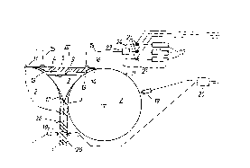
schematically illustrated in the drawing. Fig.~1 shows
a side view of an arrangement according to the
invention for continuously casting a thin strip
according to a first embodiment. Fig. 2 illustrates a
detail from this Fig. 1, and Fig. 3 is a top view in
the direction of the arrow III of Fig. 1. Fig. 4 is a
diagram illustrating the gas sweeping of individual
circumferential zones.
A continuous casting mould formed by two casting rolls
2 arranged adjacent and parallel to one another serves
to cast a thin strip 1, in particular a steel strip
having a thickness of between 1 and 10 mm. The casting
rolls 2 form a casting gap 3, the so-called "kissing
point", on which the strip 1 emerges from the
' CA 02325537 2000-09-22
continuous casting mould. Above the casting gap 3,
there is formed a space 4 which is upwardly screened by
a cover plate 5 forming a cover and which serves to
receive a melt bath 6. The metal melt 7 is supplied via
an opening 8 of the cover, through which an immersed
tube projects into the melt bath 6 as far as to below
the bath level 9. The casting rolls 2 are provided with
an internal cooling not illustrated. Laterally of the
casting rolls 2, side plates 10 are provided for
sealing the space 4 receiving the melt bath 6.
A strand shell 12 forms on the surfaces 11 of the
casting rolls 2, said strand shells being united to
form a strip 1 in the casting gap 3, i.e. on the
kissing point. For the optimum formation of a strip 1
with an approximately uniform thickness - preferably
with a slight curvature conforming to standards - the
presence in the casting gap 3 of a specific rolling
force distribution in rectangular form is essential.
The cover plate 5 is arranged in such a manner that a
gap 13 of slight width is provided between the cover
plate and the surfaces 11 of the casting rolls 2, which
gap is externally sealed relative to the surfaces 11 of
the two casting rolls 2 by means of an optionally
resilient sealing lip 14, a labyrinth seal, etc. in
order to prevent air from getting in. The edge of the
cover plate 5 that is directed towards the casting
rolls 2 is adapted in each case to the surfaces 11 of
the casting rolls 2 so as to form a gap 13 having an
approximately constant width. Inert gas is fed via this
gap 13 by means of gas feeding ducts 15 fastened to the
cover plate 5 by means of quick couplings 16, one quick
coupling 16 advantageously being provided for two or
more gas feeding ducts 15 at a time . What is important
is a tight and precise connection, which may also be in
the form of a butt joint, since the gas pressures in
the individual gas feeding ducts 15 need not be
identical. Bores 17 (which could also be slits) are
CA 02325537 2000-09-22
_ g _
provided in the cover plate as an extension of the gas
feeding ducts 15 and, via a gas outlet opening 18, open
into the gap 13 between the cover plate and the
respective casting roll 2. These bores 17 may also open
out at the lower end of the gap 13 in the already
horizontal edge region of the cover plate 5. The
diameters or gap widths of the gas outlet openings 18
are smaller than 5 mm and, preferably, smaller than
3 mm.
The surfaces 11 of the casting rolls 2 are swept with
an inert gas as a function of their condition, to which
end the surfaces 11 of the casting rolls 2 are provided
by means of [sic] a device 19 for observing them.
According to the exemplary embodiment illustrated, a
profile sensor 19 is directed in each case towards a
surface 11 of a casting roll 2, measuring a temperature
profile integrally over the longitudinal extent of each
casting roll 2. The profile sensor 19 is coupled with a
computer and control unit 20 in such a manner that
temperature values or temperature mean values may each
be allocated to adjacently located partial surface
areas a, b, c, ..., i.e. individual adjacent
circumferential zones a, b, c, ... distributed over the
longitudinal extent of the casting rolls 2.
The profile sensor 19 could also be replaced with a
radiation sensor for detecting smooth sites on the
surfaces 11 of the casting rolls 2.
In order to be able to influence, by means of inert
gas, individual zones of the adjacently located
circumferential zones a, b, c, ... of each casting roll
2 separately and independently of one another, a
plurality of gas feeding devices 21 is provided,
according to the exemplary embodiment illustrated, each
gas feeding device 21 being allocated to a
circumferential zone a, b, c, ... of a casting roll 2.
' ' CA 02325537 2000-09-22
- 10 -
Compressed gas reservoirs 22 for different gases are
provided for gas sweeping; for instance, three
compressed gas reservoirs 22 according to the exemplary
embodiment illustrated, wherein each of the compressed
gas reservoirs 22 is filled with a specific gas, e.g.
one with nitrogen, one with argon and one with helium.
From each of these compressed gas reservoirs 22, gas
ducts 24 lead to a mixing chamber 23 associated with in
each case one of the circumferential zones a, b, c,
..., wherein a specific gas composition formed from one
or more of the gases contained in the compressed gas
reservoirs 22 may be set in each of the mixing chambers
23 by means of throttle and shut-off members 25
installed in the gas ducts 24. These throttle and shut-
off members 25 are coupled with the controller 20 and
are activated by the same such that a specific gas
composition in accordance with the temperature profile
present over the longitudinal extent of each casting
roll 2 may be set for each mixing chamber 23 and hence
for each of the circumferential zones a, b, c, .... The
set values to be selected are determined by the
controller 20 on the basis of the temperature profiles
detected by the respective sensor 19.
A gas feeding duct 15 leads from each of the mixing
chambers 23 to a gas outlet opening 18 provided on the
edge of the cover plate 5, whereby the surfaces 11 of
the casting rolls 2 may each be acted upon by different
gas compositions, i.e, locally different gas mixtures -
viewed in the longitudinal direction of the casting
rolls 2 - in a circumferential-zone-related manner. It
is also possible to combine several adjacently located
gas outlet openings 18 (e.g., in the form of bores) to
form a group and to feed them from a single gas feeding
duct 15, whereby wider circumferential zones a, b, c,
... are formed, i.e. larger surface areas of the
surfaces 11 are each supplied with a gas mixture. Hence
it results that a gas feeding device for feeding gas to
a circumferential zone a, b, c, ... is formed from gas
' CA 02325537 2000-09-22
- 11 -
ducts 24 (their number corresponding to the number of
compressed gas reservoirs 22), throttle and shut-off
members 25, a mixing chamber 23, a gas feeding duct 15
and at least one gas outlet opening 18.
The incoming gas should have impact pressures of at
least 1.05 bar and, preferably, more than 1.5 bar up to
2 bar, wherein the axes of the gas outlet openings 18
may be substantially perpendicular to the casting roll
surface, yet are inclined in, or opposite to, the
direction of movement of the roll surface, to be
precise in the range of + 60°. The choice of the widths
of the circumferential zones a, b, c, ... depends on
the possible susceptibility to failures of the casting
process, which, in turn, is largely a function of the
process parameters.
According to another embodiment of the invention, the
surfaces 11 of the casting rolls 2 are not directly
observed, but a conclusion is drawn as to the
conditions of the surfaces 11 of the casting rolls 2
from a direct observation of one of the surfaces 26, or
both of the surfaces 26, of the strip 1. Consequently,
the sensors 19 in this embodiment are directed towards
the surfaces 26 of the strip 1, i . a . as immediately as
possible after the emergence of the strip 1 from the
casting gap 3, as indicated in Fig. 1 by dot-and-dash
lines.
The invention is not limited to the exemplary
embodiments depicted in the drawing, but may be
modified in various respects. It is, for instance,
possible to achieve the object underlying the invention
by observing the local surface roughness of the casting
rolls 2 instead of measuring the locally occurring
temperature on the casting roll surfaces 11.
Conclusions may also be drawn from observing the
surface reflection properties of the casting rolls 2,
or of the strip 1, by means of image recognition
' CA 02325537 2000-09-22
- 12 -
systems, or locally different discolorations of the
surfaces of the casting rolls 2 may be observed and
used for selecting the gas composition to be swept
towards the circumferential zones.
The surfaces 11 of the casting rolls 2 may also be
influenced by additionally adjusting locally different
gas amounts and/or locally different gas pressures
instead of the local variation of the gas composition.
Fig. 4 represents schematically in diagram form the
different feeds of different gas compositions A, B, C,
... to circumferential zones a, b, c, .... The
individual adjacently arranged circumferential zones a,
b, c, ... are plotted on the abscissa of the diagram.
In sum, they correspond to the length of a casting roll
11. In the direction of the ordinate, the temperature
values allocated to the individual circumferential
zones a, b, c, ... are plotted, a temperature profile
according to line 27 resulting from a very fine
measurement. In addition, gas quantity values with
which the individual circumferential zones a, b, c, ...
are swept per time unit are plotted in the ordinate
direction. References A, B, C, ... relate to different
gas compositions such as may be formed by mixing the
different gases contained in the compressed gas
reservoirs 22. It is apparent that each temperature
mean value of a circumferential zone a, b, c, ... (the
mean values being indicated by broken lines) is
allocated a defined gas composition and a defined gas
amount to act on the circumferential zones a, b, c,
The invention is based on the idea that local
influencing of a partial surface of the overall surface
11 of a casting roll 2 is possible by means of locally
differently fed gas mixtures or gas amounts when
feeding these gas mixtures just above the melt bath
level 9. By way of experiments, it has been shown that
~
~ CA 02325537 2000-09-22
- 13 -
different gas mixtures inducing different
solidification rates may be introduced even into
closely adjacent regions, i.e. even into directly
adjacent regions of the melt bath level 9 while,
nevertheless, it is possible to exert different
influences on adjacently located surface zones or
circumferential zones a, b, c, ... of the casting rolls
2, thereby preventing the surfaces 11 of the casting
rolls 2 from becoming non-uniform.. As a result, the
surfaces 11 of the casting rolls 2 will require repair
or replacement only after considerably longer casting
sequences or substantially higher product tonnages than
has been the case until now.
By way of an experiment it has been shown that the
solidification speed may be kept lower by up to 30~
when using 100 argon than with the use of 100 helium.
Thus, it was found that zones on the surfaces 11 of the
casting rolls 2 exhibiting red-brownish discolorations
or stains could be removed again by increasing the
supply of helium, which considerably increases the
local solidification rate; the red-brown coloration
fades or disappears. Furthermore, it was found that in
regions of glossy stains the solidification rate can be
reduced by increasing the argon feed, thereby causing
the glossy stains to disappear again. In general,
varying casting roll surface conditions over the
longitudinal extent of the casting rolls 2 are
eliminated by the process according to the invention
and the scattering range of the surface quality
differences during, or on account of, the casting
procedure does not increase, but heat transfer in the
event of local changes to the surfaces is influenced by
a change in the locally applied gas mixture in such a
manner that these changes to the surface do not
increase, but decline again. By surface quality, its
roughness, optical reflection properties,
discolorations, stains, or the presence of striae or
dimples, for example, are to be understood.
' ' CA 02325537 2000-09-22
- 14 -
In accordance with the invention, the solidification
structure, in particular the central globulitic-dentric
solidification structure, of the strip 1 produced will
become more uniform over the total width, on the one
hand, and reconditioning (rendering the surfaces 11 of
the casting rolls 2 uniform) will be required only
after a larger number of casts, on the other hand.
Thus, not only the service life of .the surface layer,
but also, in particular, the service life of the
casting rolls 2 as a whole will be markedly increased.