Note: Descriptions are shown in the official language in which they were submitted.
CA 02325728 2000-11-10
TITLE OF THE INVENTION:
Flow Control Mechanism For An Eaves Trough Downspout
FIELD OF THE INVENTION
The present invention relates to a flow control mechanism
for an eaves trough downspout
BACKGROUND OF THE INVENTION
There are many persons who chose to capture rain water.
They do this by directing their eaves trough downspout into a
rain barrel. It is undesirable to permit uncontrolled overflow
of rainwater from the rain barrel, as such an overflow next to
a basement of a house can potentially lead to the basement
flooding.
Persons collecting rain water are rarely available to
closely monitor the quantity of rain accumulating in their rain
barrels. For this reason flow control mechanism for eaves
trough downspouts have been developed. An example of such a
flow control mechanism is United States Patent 4,428,394 which
issued to Wright in 1984. The Wright patent discloses a
deflector baffle positioned in a section~of downspout which can
be positioned to either deflect water flowing through the
downspout into a rain barrel or into a conduit leading
elsewhere. The position of the deflector is determined by an
associated float mechanism that extends into the rain barrel.
A disadvantage of the Wright patent is that in order for the
float to function, the rain barrel must be positioned
immediately adjacent to the eaves trough downspout.
SUMMARY OF THE INVENTION
What is required is a flow control mechanism for an eaves
trough downspout that will give more flexibility on rain barrel
positioning.
CA 02325728 2000-11-10
2
According to the present invention there is provided a
flow control mechanism for an eaves trough downspout which
includes a housing having an inlet, a first outlet, and a
second outlet. A primary flow path is provided through the
housing being provided between the inlet and one of the first
outlet and the second outlet. A tubular arm extends from the
housing. The arm has a first end and a second end. The first
end is in fluid communication with the second outlet. A
deflector is pivotally secured within the housing for movement
between a deflecting position and an inoperative position. In
the deflecting position, the deflector is adapted to deflect
a liquid stream flowing along the primary flow path to a
secondary flow path through the other of the first outlet and
the second outlet. In the inoperative position, the deflector
is spaced from the primary flow path. A linkage extends
through the tubular arm. The linkage has a first end and a
second end. The first end of the linkage is secured to the
deflector. A float is positioned at the second end of the
tubular arm and suspended from the second end of the linkage.
Movement of the deflector between the deflecting position and
the inoperative position is tied by the linkage to the position
of the float.
The flow control mechanism, as defined above, enables a
rain barrel to be positioned at a distance from the downspout.
This is made possible by the linkage that extends through the
arm. This feature enables the rain barrel to be positioned on
an edge of the garden or wherever may be most convenient for
the user. There is no need to change the basic downspout
configuration, as the described flow control mechanism can be
inserted into a section of the existing downspout. Unlike the
Wright flow control mechanism, the rain barrel does not have
to be uncovered for the mechanism to work. This enables the
rain barrel to be fitted with a lid to keep out debris.
Although beneficial results may be obtained through the
use of the flow control mechanism, as described above, it is
CA 02325728 2000-11-10
3
undesirable for debris from the roof to be deposited into the
rain barrel. Even more beneficial results may, therefore, be
obtained when a debris screen is positioned at an angle across
the primary flow path upstream of the deflector to deflect
debris in liquids flowing along the flow path to a tertiary
flow path leading to the first outlet. This additional
features prevents most debris from passing through the second
outlet.
Other additional features which improve the operation of
the flow control mechanism, will hereafter be described in
relation to the structure and operation of the flow control
mechanism.
BRIEF DESCRIPTION OF THE DRAWINGS
These and other features of the invention will become more
apparent from the following description in which reference is
made to the appended drawings, the drawings are for the purpose
of illustration only and are not intended to in any way limit
the scope of the invention to the particular embodiment or
embodiments shown, wherein:
FIGURE 1 is a side elevation view, in section of a flow
control mechanism for an eaves trough downspout constructed in
accordance with the teachings of the present invention, with
its deflector in a deflecting position.
FIGURE 2 is a side elevation view, in section of the flow
control mechanism illustrated in FIGURE l, with its deflector
in an inoperative position.
DETAILED DESCRIPTION OF THE PREFERRED EMBODIMENT
The preferred embodiment, a flow control mechanism for an
eaves trough downspout generally identified by reference
numeral 10, will now be described with reference to FIGURES 1
and 2.
Structure and Relationship of Parts:
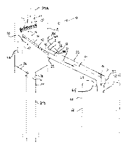
Referring to FIGURE 1, flow control mechanism 10 includes
CA 02325728 2000-11-10
4
a housing 12 that has an inlet 14, a first outlet 16, and a
second outlet 18. A primary flow path 20 is provided through
housing 12 between inlet 14 and first outlet 16 as indicated
by arrow 20. A first coupling 22 is provided for coupling
inlet 14 to an upper section 24A of eaves trough downspout 24.
A second coupling 26 is provided for coupling first outlet 16
to a lower section 24B of eaves trough downspout 24.
A tubular arm 28 extends from housing 12. Tubular arm 28
has a first end 30 and a second end 32. Tubular arm 28 has a
flange 63 positioned adjacent second end 32. Tubular arm 28
has a corrugated portion 29 at first end 30. Corrugated portion
29 provides flexibility so that tubular arm 28 can be lifted
enough to facilitate insertion and removal of tubular arm 28
in an opening 64 in a lid 62 of a rain barrel 60. A support
line 31 is provided that extends from a first anchoring member
33A positioned on housing 12 to a second anchoring member 33B
on tubular arm 28 so as to support tubular arm 28 in such a
manner that tubular arm 28 won't fall as a result of the
flexibility of corrugated portion 29. When tubular arm 28 is
to be raised to accommodate removal of rain barrel 60, support
line 31 can be disengaged from first anchor member 33A and
engaged to a third anchor member 33C positioned on housing 12
above first anchor member 33A. This enables tubular arm 28 to
be maintained in a slightly raised position while rain barrel
60 is properly positioned. When rain barrel 60 is properly
positioned, support line 31 is disengaged from third anchoring
member 33C, tubular arm 28 is lowered to the appropriate
position, and support line 31 is again engaged to first anchor
member 33A. Corrugated portion 29 at first end 30 of tubular
arm 28 is in fluid communication with second outlet 18. A
deflector 34 is pivotally secured within housing 12 for
movement between a deflecting position, as illustrated in
FIGURE l, and an inoperative position, as illustrated in FIGURE
2. Referring to FIGURE 1, in the deflecting position,
deflector 34 is adapted to deflect a liquid stream 36 flowing
along primary flow path 20 to a secondary flow path through
second outlet 18, indicated by arrow 38. Referring to FIGURE
CA 02325728 2000-11-10
2, in the inoperative position, deflector 34 is spaced from
primary flow path 20. Referring to FIGURE 1, deflector 34 has
an eccentrically positioned pivot axis 40 that biases deflector
34 into the deflecting position. The flow of water along
5 primary flow path 20 striking deflector 34, tends to maintain
deflector 34 in the deflecting position. A support 42 is
secured within housing 12 to support deflector 34 when in the
deflecting position. A rigid linkage 44 extends through
tubular arm 28. Linkage 44 has a first end 46 and a second end
48. First end 46 of linkage 44 is secured to deflector 34.
Linkage guides 50 are positioned within tubular arm 28, so as
to support and guide movement of linkage 44. A float 52 is
positioned at second end 32 of tubular arm 28 and is suspended
from second end 48 of linkage 44, such that movement of
deflector 34 between the deflecting position as illustrated in
FIGURE 1, and the inoperative position as illustrated in FIGURE
2, is tied by linkage 44 to the position of float 52. A his
screen 54 is positioned at an angle across primary flow path
upstream of deflector 34, to deflect debris 56 carried by
20 water 36 flowing along primary flow path 20 to a tertiary flow
path leading to first outlet 16, as indicated by arrow 58.
This prevents debris from being deflected by deflector 34 and
passing through second outlet 18.
Operation:
The use and operation of flow control mechanism 10 will
now be described with reference to FIGURES 1 through 2.
Referring to FIGURE 1, flow control mechanism 10, as defined
above, enables a collection container 60 such as a rain barrel
to be positioned at a distance from eaves trough downspout 24.
The ability to position rain barrel 60 at a distance from eaves
trough downspout 24 is made possible by linkage 44 that extends
through tubular arm 28. Movement of deflector 34 between the
deflecting position as illustrated in FIGURE 1, and the
inoperative position as illustrated in FIGURE 2, is tied by
linkage 44 to the position of float 52. Linkage 44 allows for
float 52 to function with deflector 34 so as to prevent an
CA 02325728 2000-11-10
6
overflow despite rain barrel 60 being placed at a distance from
eaves trough downspout 24.
Referring to FIGURE 1, in the illustrated embodiment, rain
barrel 60 has a lid 62 with an opening 64. Float 52 is
suspended from linkage 44 through opening 64 in lid 62. Flange
63 positioned adjacent second end 32 of tubular arm 28 rests
upon lid 62. Flange 63 prevents dirt and other debris from
entering rain barrel 60 through opening 64 in lid 62. When
liquid level 66 in rain barrel 60 is low, float 52 is suspended
above liquid level 66. The weight of float 52 in conjunction
with gravity, pulls linkage 44 which in turn moves deflector
34 into the deflecting position. When in the deflecting
position, water 36 entering flow control mechanism 10 though
inlet 14 is directed by deflector 34 toward second outlet 18
along secondary flow path 38 through tubular arm 28 and into
rain barrel 60. As water 36 flows into rain barrel 60, liquid
level 66 rises in rain barrel 60. When liquid level 66 reaches
float 52, float 52 then rises with liquid level 66 thereby
pushing up on linkage 44. Referring to FIGURE 2, when float
52 pushes on linkage 44, linkage 44 moves deflector 34 to the
inoperative position. With defector 34 in the inoperative
position, water 36 flows directly along primary flow path 20
into eaves trough downspout 24, bypassing rain barrel 60.
Referring to FIGURE 1, if liquid level 66 is lowered in rain
barrel 60 by more than a preset amount, deflector 34 is moved
to the deflecting position by downward movement of float 52 and
water 36 is permitted to flow along tubular arm 28 and into
rain barrel 60 again. Float can be made adjustable by means of
a screw style of adjustment in the same fashion as is commonly
used with a toilet float.
In this patent document, the word "comprising" is used in
its non-limiting sense to mean that items following the word
are included, but items not specifically mentioned are not
excluded. A reference to an element by the indefinite article
"a" does not exclude the possibility that more than one of the
element is present, unless the context clearly requires that
CA 02325728 2000-11-10
7
there be one and only one of the elements.
It will be apparent to one skilled in the art that
modifications may be made to the illustrated embodiment without
departing from the spirit and scope of the invention as
hereinafter defined in the Claims.