Note: Descriptions are shown in the official language in which they were submitted.
CA 02325979 2004-07-08
Docket No. 1202P-0002261CPD
ALL-LINKAGE RECLINING CHAIR
WITH IMPROVED TENSIONING MECHANIShI
BACKGROUND OF THE INVENTION
1. Technical Field
The present invention relates generally to an all-linkage wail proximity
reclining
mechanism for a chair and more particularly to a tensioning mechanism for
adjusting
the effort associated with the reclining motion.
2. Description of Related Art
Wall proximity reclining chairs are known within the art; and are becoming
increasingly popular as it becomes more desirable to integrate comfort and
reclining
functions into various articles and styles of furniture including chairs, love
seats and
sofas. Many of the first developed designs were based upon all-linkage
mechanisms.
However, these all-linkage mechanisms typically did not provide a smooth
reclining
motion. To overcome this problem, wall proximity reclining mechanisms
utilizing track
and roller assemblies were developed to provide a smoother reclining motion.
-1-
CA 02325979 2004-07-08
Presently, the reclining mechanisms utilizing track and rollers are relatively
complex
and are thus expensive to manufacture.
An exemplary track and roller reclining chair mechanism which was developed
to provide of smoother reclining motion is that disclosed in U.S. Patent No.
5,011,220,
entitled "Chair Mechanism", which is commonly owned by the assignee of the
present
invention. This mechanism utilizes a short inclined track and roller to
provide the
reclining motion of the wall proximity reclining chair. While this chair
mechanism
achieved the goal of providing smoother reclining operation, the design of
this
mechanism presents several disadvantages. First, this mechanism is limited to
only two
operative positions, namely the upright position, and the fully-reclined
position.
Additionally, this chair design does not allow the chair arms to move along
with the seat
assembly. Thus, this chair design requires a chair frame having more forwardly
extending arm rests for providing adequate support when the chair mechanism is
in the
fully reclined position.
Another exemplary wall proximity reclining chair is that disclosed in U.S.
Patent
No. 5,217,276, entitled "Chair Mechanism", which is commonly owned by the
assignee
of the present invention. This chair' mechanism design provides several
improvements
over those mechanisms known within the art. However, this mechanism also
relies
upon a track and roller system for providing smooth reclining motion.
Additionally, this
chair is limited to only two reclining positions, and requires manual
actuation via a hand
-2-
CA 02325979 2004-07-08
operated lever. Accordingly, this design limits the types of furniture within
which this
mechanism can be integrated.
Yet another type of wall proximity reclining chair is that illustrated in U.S.
Patent
No. 5,323,526, entitled "Method for Assembling A Modular Wall Proximity
Reclining
Chair", which is commonly owned by the assignee of the present invention. This
chair
was developed for reducing the complexity of the reclining mechanism, and the
method
for assembling the reclining mechanism. This chair mechanism surmounted the
disadvantages of the prior art designs by providing a side frame and arm rest
assembly
that moves in conjunction with the seat assembly for providing adequate arm
rest
support. However, this mechanism design also relies upon a full length track
and roller
assembly for providing the desired smoothness in the reclining operation. The
requirement for a bearing based roller assembly also increases the cost of the
mechanism. Additionally, the design of this mechanism limits this chair to a
single
reclining chair and further prevents this mechanism from being used in larger
articles
of furniture, such as loveseats, sofas and modular sofa assemblies.
The all-linkage reclining chair mechanisms known within the art also do not
provide. adequate adjustment features for accommodating seat occupants of
varying
stature. In view of the growing popularity of wall proximity chairs, there is
an increasing
need to develop a wall proximity reclining chair mechanism which can be
utilized with
various types of furniture at a considerably lower cost and that provides the
comfort
features demanded by consumers. As such, it is desirable to provide an all-
linkage wall
proximity reclining chair which delivers smooth reclining motion and
-3-
CA 02325979 2000-11-15
Docket No. 1202P-000226/CPD
includes an adjustment feature~for accommodating various sized seat occupants.
It
is also desirable to provide an all-linkage reclining chair mechanism which is
designed to be primarily gravity driven with the assistance of a spring
biasing
mechanism, rather than manually driven by the occupant using an externally
mounted
operating handle. Such a design would simplify the operation of the chair. It
is
further desirable to provide an all-linkage reclining chair mechanism
adaptable for use
in a wide variety of motion furniture such as chairs, love seats and sofas. It
is also
desirable to provide a wall proximity reclining chair mechanism in which the
leg rest
assembly can be fully extended by actuating a compact trigger release
assembly, and
can be retracted by the occupant merely moving the leg rest assembly back into
the
chair mechanism by leaning forward and placing a small amount of force onto
the leg
rest assembly. Finally, it is desirable to provide a reclining mechanism in
which the
leg rest assembly can be replaced in the field, if damaged during use, without
disassembling the entire chair mechanism.
SUMMARY OF THE INVENTION
In accordance with the principles of the present invention, an all-linkage
wall
proximity reclining chair is disclosed which can be readily incorporated into
several
different types of furniture. The reclining chair includes a base, and a
support linkage
assembly pivotally supported from the base. A longitudinal link is operably
interconnected to the support linkage assembly. A recline linkage assembly is
operably coupled to the longitudinal link and to the base for controlling
movement of
the longitudinal link from an upright position to at least one reclined
position. A
-4-
CA 02325979 2004-07-08
rotatable drive shaft is journally supported by the longitudinal link. The
reclining chair
further includes a leg rest assembly supported from the longitudinal link and
operably
coupled to the drive shaft for movement from a retracted position to an
extended
position in response to rotation of the drive shaft. A tensioning mechanism is
operably
disposed between the base and the support linkage for biasing the longitudinal
link
toward the reclined position. The tensioning mechanism is adjustable for
varying the
biasing force associated therewith.
In a broad aspect, then, the present invention relates to a reclining
mechanism
comprising: a base frame; a support linkage assembly including a first support
linkage
pivotally coupled to said base frame, a second support linkage pivotally
coupled to said
base frame, and a cross member pivotally coupled to said first support linkage
at a first
pivot and pivotally coupled to said second support linkage at a second pivot;
and an
adjustable drive spring assembly operably disposed between said base frame and
said
rear cross member to forwardly bias said support linkage assembly, said drive
spring
assembly including a spring member having a first end connected to said base
frame
and a second end operably coupled to said rear cross member and a continuous
tension adjusting mechanism for continuously adjusting the tension in said
spring
member.
In another broad aspect, then, the present invention relates to a reclining
mechanism comprising: a base frame having a pair of longitudinal base rails
and a
cross member; a support linkage assembly having a first intermediate link, a
first
support linkage including a pair of first support links pivotally coupled at a
first end to
one of said pair of longitudinal base rails and pivotally coupled to said
first intermediate
link at a second end, and a second support linkage including a pair of second
support
CA 02325979 2004-07-08
links interconnected by said cross member, said pair of second support links
pivotally
coupled at a first end to the other of said pair of longitudinal base rails
and pivotally
coupled to a second intermediate fink at a second end; and an adjustable drive
spring
assembly including a continuous tension adjusting mechanism supported by said
cross
member and positionable relative to said cross member and a spring member
having
a first end connected to said cross rail of said base frame and a second end
operably
coupled to said continuous tension adjusting mechanism such that tension in
said
spring member may be selectively set.
Additional objects, advantages and features of the present invention will
become
apparent from the following description and appended claims, taken in
conjunction with
the accompanying drawings.
DESCRIPTION OF THE DRAWINGS
Figures 1A through 1C are perspective views of an exemplary wall proximity
recliner showing the various operative positions, including an upright
position with the
leg rest assembly retracted, a partially reclined position with the leg rest
assembly fully
extended, and a fully reclined position with the leg rest assembly extended
and the seat
back fully reclined;
Figure 2 is an outside elevational view of an all-linkage mechanism in
accordance with a preferred embodiment of the present invention with the
upholstery,
springs and other parts removed from the reclining mechanism for illustrating
the
integrated and inter-dependent association of the linkage components;
-5a-
CA 02325979 2000-11-15
i
Docket No. 1202P-000226/CPD
Figure 3 is a top plan view showing the all-linkage mechanism interconnected
with various cross members and the adjustable tensioning mechanism in
accordance
with a preferred embodiment of the present invention;
Figure 4 is a partial cross-sectional view of the all-linkage mechanism in an
upright position and further illustrating the adjustable tensioning mechanism
in
accordance with a preferred embodiment of the present invention;
Figure 5 is a partial cross-sectional view similar to Figure 4 showing the all-
linkage mechanism in a reclined position;
Figure 6 is a cross-section taken along line VI-VI illustrated in Figure 5;
Figure 7 is a cross-section taken along line VII-VII illustrated in Figure 4;
Figure 8 is a partial perspective view of the all-linkage mechanism
illustrating
the seat back attachment bracket in a first configuration; and
Figure 9 is a partial perspective view of the all-linkage mechanism
illustrating
the seat back attachment bracket in a second configuration.
DETAILED DESCRIPTION OF THE INVENTION
In accordance with the teachings of the present invention, an all-linkage wall
proximity recliner adapted for use in various articles of motion furniture is
disclosed.
In a preferred embodiment, a pair of all-linkage recliners 20, 20' are
integrated into
a love seat in which the recliners 20, 20' independently recline. However, it
should
be understood that the all-linkage mechanisms of the present invention can be
incorporated into a variety of motion furniture designs. With particular
reference now
-6-
CA 02325979 2000-11-15
Docket No. 1202P-000226/CPD
to the drawings, the structural and functional aspects of the present
invention are
described with more particular detail.
With reference now to Figures 1A through 1 C, wall proximity reclining chair
20
includes a seat frame 22 having an arm rest or side frame 24, and further
includes
a reclinable seat back 26 and movable leg rest assembly 28. Figure 1A
illustrates
wall proximity reclining chair 20 in its upright position, with leg rest
assembly 28
retracted within the chair. Figure 1 B illustrates the wall proximity
reclining chair 20
in its partially reclined or intermediate position, in which leg rest assembly
28 is fully
extended and seat back 26 is partially reclined. Leg rest assembly 28 is
positionable
between a retracted position shown in Figure 1A and an extended position as
shown
in Figures 1 B and 1 C. Figure 1 B further illustrates the wall proximity
feature in that
seat frame 22, side frame 24, and seat back 26 move forwardly along with leg
rest
assembly 28 when the wall proximity reclining chair 20 is moved from its
upright
position to its partially reclined position. Finally, Figure 1 C illustrates
wall proximity
reclining chair 20 in its fully reclined position. It should be noted that leg
rest
assembly 28 must be fully extended before seat back 26 can begin reclining. As
will
be appreciated from Figure 1 C and the following detailed description, when
wall
proximity reclining chair 20 is in the partially reclined position, additional
rearward
pressure placed against seat back 26 by the occupant, correspondingly forces
the
seat frame 22, side frame 24 and leg rest assembly 28 forward. Accordingly,
the all-
linkage mechanism is designed to allow seat back 26 to be placed within
approximately 5-6 inches (12-15 cm) of a wall surface and achieve a fully
reclined
position without seat back 26 making contact with the proximal wall surface.
-7-
CA 02325979 2000-11-15
Docket No. 1202P-0002261CPD
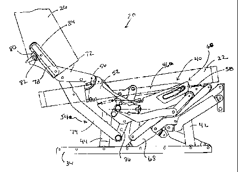
Referring now to Figures 2 and 3, the preferred embodiment of the present
invention is illustrated in more detail. Wall proximity reclining chair 20
includes right
and left all-linkage mechanisms 30, 32. It should be understood that the all-
linkage
mechanisms 30, 32 are mirror images of each other. Each all-linkage mechanism
30,
32 is pivotably secured to a longitudinal "L-shaped" base rail 34. Referring
briefly to
Figure 3, the pair of longitudinal base rails 34 are then secured to front and
rear "L-
shaped" frame rails 36, 38.
Referring again to Figures 2 and 3, the individual components forming each
all-linkage mechanism are described in more detail. Each all-linkage mechanism
30,
32 is generally supported from its longitudinal base rail 34 by a four-bar
linkage
assembly 40. More specifically, the four-bar linkage assembly 40 includes a
front
support link 42 and a rear support link 44 which are pivotably coupled at
their lower
ends to the vertical flange of the longitudinal base rail 34. Additionally,
the front
support link 42 and the rear support link 44 are pivotably coupled at their
upper ends
to the secondary longitudinal or intermediate link 46. The right and left all-
linkage
mechanisms 30, 32 are interconnected to each other by a front cross member 48
which connects between the front support links 42, and a rear cross member 50
which connects between the rear support links 44.
The prominent link of each all-linkage mechanism 30, 32 is the main
longitudinal link 52 which supports the seat frame 22 and side frame or frames
24.
The forward end of main longitudinal link 52 is directly supported by the
front support
link 42, and the rearward end of longitudinal link 52 is indirectly supported
by the
recline linkage assembly 54. The main longitudinal link 52 further includes
front and
_g_
' CA 02325979 2004-07-08
Docket No. 1202P-0002261CPD
rear flanges 56, 58 which protrude outwardly from the main longitudinal link
52 for
supporting and securing the seat frame 22 and side frame 24.
The adjustable seat slide 60 controls how easily the main longitudinal link 52
can move with respect to front support link 42. Thus, the adjustable seat
slide 60
controls the amount of friction between longitudinal link 52 and support link
42 during
the reclining motion. Each all-linkage mechanism 30, 32 further includes a
recline
linkage assembly 54 which is defined by a first position recline linkage 62,
and a
second position recline linkage 64. The first position recline linkage 62
includes a
first connecting link 66, a base connecting link 68 and a second connecting
link 70.
9 0 The primary function of the first position recline linkage 62 is to
control the forward
motion of the four-bar linkage 40 supporting the main longitudinal link 52 as
the chair
20 reclines away from the wall surface into the intermediate position.
The second position recline linkage 64 includes a seat back support link 72,
a recline connecting link 74, and a vertical pivoting drive link 76. The
primary
function of the second position recline linkage 64 is to control the forward
motion of
the main longitudinal link 52 from the intermediate position to the fully
reclined
position, and to control the reclining motion of the seat back 26. The
upstanding
portion 78 of the seat back supporting link 72 includes a rearward facing
notch 80 for
receiving the locking cam mechanism 82 of the seat back connecting bracket 84.
The seat back connecting bracket 84 is secured to the upright side frame
member of
the detachable seat back 26 with suitable fasteners. A more detailed
description of
the components associated with the seat back connecting bracket 84 can be
found
in U.S. Patent No. 5,184,871, entitled "Detachable Chair Back",
_g_
CA 02325979 2004-07-08
Docket No. 1202P-0002261CPD
which is commonly owned by the Assignee of the present invention.
With reference now to Figures 3-7, the wall proximity reclining chair 20 is
also
provided with an adjustable drive spring assembly 86 which provides a forward
bias
to the four-bar linkage 40, and assists in the reclining of the chair 20.
Adjustable
drive spring assembly 86 includes spring member 88 operably coupled between
front
frame rail 36 and rear cross member 50. Tensioning mechanism 90 is supported
by
rear cross member 50 and connects to the rear end of spring member 88.
Tensioning mechanism 90 includes bushing 92 inserted within an aperture 94
formed
in rear cross member 50 and rotatably supports threaded stud 96. Adjusting
wheel
98 is threadingly received on stud 96 and cooperates with bushing 92 for
selectively
adjusting the length of tensioning mechanism 90. An aperture 102 formed
through
threaded stud 96 on an end opposite adjusting wheel 98 receives a retaining
clip 100
for operably coupling spring member 88 to tensioning mechanism 90. A retaining
washer 104 is used on clip 100 for preventing uncoupling of tensioning
mechanism
90 from spring 88.
Adjustable drive spring assembly 86 is operable to increase or decrease, and
thereby adjust, the preload in spring member 88 for providing a forward bias
to the
four-bar linkage 40. More specifically, by adjusting the effective length of
tensioning
mechanism 90 between rear cross rail 50 and spring member 88, the preload may
be adjusted. To this end, wheel 98 is provided with a set of female threads
which are
complementary to the male threads formed on threaded stud 96. As presently
preferred, a suitable power transfer thread configuration such as an Acme
thread is
-10_
CA 02325979 2004-07-08
Docket No. 1202P-000226/CPD
utilized to provide adequate mechanical advantage while minimizing the number
of
turns required to adjust the effective length of tensioning mechanism 90. For
example, an Acme thread having a pitch of eight (8) threads per inch is
presently
preferred.
As best seen in Figure 6, bushing 92 and stud 96 are provided with flat side
walls which are complementary to aperture 94 formed through cross member 50 to
prevent rotation of bushing 92 and stud 96 upon rotation of wheel 98. In
addition,
bushing 92 is provided with a tapered shoulder 106 which engages a rear
surface of
the web 108 formed on cross member 50. As seen in Figure 4, only the thick
portion
of shoulder 106 formed on bushing 92 engages web 108 when the reclining chair
is
in an upright position. In this orientation, adjusting wheel 98 is
substantially parallel
with the web 108 of rear cross member 50. As the reclining chair moves to a
reclined
position, cross member 50 rotates downwardly off vertical. As a result,
bushing 92
rotates within aperture 94 such that the entire length of shoulder 106 engages
web
108. Adjusting wheel 98 takes on an angular orientation with respect to web
108,
shoulder 106 functions to maintain adequate spacing between adjusting wheel 98
and
web 108 to provide free manipulation thereof.
Turning now to Figures 8 and 9, yet another aspect of the present invention
is illustrated which provides additional flexibility and adaptability of the
all-linkage
reclining mechanism for use in various furniture configurations. More
specifically,
seat back support link 72 may be operably coupled to main longitudinal link 52
and
recline connecting link 74 in a manner to significantly adjust the seat back
width
accommodated thereby. For example, as illustrated in Figure 8, seat back
support
-11-
CA 02325979 2004-07-08
Docket No. 9202P-0002261CPD
link 72 may be pivotally coupled on an outboard side of main longitudinal link
52 and
recline connecting link 74 by threaded rivets 110 and 112, respectively. With
reference now to Figure 9, seat back support link 72 may also be positioned in
an
alternate configuration for accommodating a relatively narrow seat back. More
specifically, by locating seat back support link 72 on the inboard side of
main
longitudinal link 52 the distance between left and right upstanding portions
78 may
accommodate a more narrow seat back frame. Seat back support link 72 is
pivotally
coupled to an inboard side of main longitudinal link 52 and recline connecting
link 74
by threaded rivets 110, 112, respectively. To further enhance the adaptability
of all-
linkage reclining mechanism 30, a threaded rivet stop 114 may be utilized on
either
the outboard side of main longitudinal link 52 as illustrated in Figure 8 or
the inboard
side of main longitudinal link 52 as illustrated in Figure 9. Stop 114 limits
the
movement of seat back support link 72.
With continued reference to Figures 2 and 3, in view of Figures 1A through 1
G,
the functional operation of wall proximity reclining chair 20 is described in
general
detail. A more specific description of the functional operation of the wall
proximity
chair 20, as well as additional detail regarding the components not fully
described
herein can be found in U.S. Patent No. 5,992,930, U.S. Patent No. 5,975,627,
and
U. S. Patent No. 6,145,924, all of which are commonly owned by the assignee of
the
present invention. Each all-linkage mechanism 30, 32 is maintained in its
upright
position by spring assist drive linkage 120. More specifically, the biasing
spring 122
operably coupled between front frame rail 36 and square drive rod 124 forces
drive
-12-
CA 02325979 2000-11-15
Docket No. 1202P-0002261CPD
rod 124 into its retracted position through over-center mechanism 126, thereby
locking the reclining chair 20 in the upright position.
Upon initiating a trip link assembly, the leg rest assembly 28 begins to
extend,
and the main longitudinal link 52 moves forwardly via the front and rear
support links
42, 44. Adjustable drive spring assembly 86 functions to bias all-linkage
mechanisms
30, 32 towards the reclined position. The effect of that biasing force is
adjustable to
accommodate seated occupants of widely varying weight, strength and stature.
As
the main longitudinal link 52 moves forwardly into the partially reclined
position, the
rear portion of the main longitudinal link 52 moves forwardly and downwardly
as the
tripartite linkage formed by the rear support link 44, first connecting link
66, base
connecting link 68, and second connecting link 70, rotates downwardly to
contact the
horizontal flange of the longitudinal base rail 34. Eventually, the tripartite
linkage
assembly, and especially the base connecting link 68, bottoms out against the
longitudinal base rail 34. The mechanism is designed so that the leg rest
assembly
28 is fully extended when the base connecting link 68 contacts the base rail
34. The
forward and downward motion of the rear portion of the main longitudinal link
52
causes the seat back 26 to also move downwardly and to be tipped rearwardly
through the seat back support link 72 and recline connecting link 74.
The second recline phase is initiated by rearward and downward pressure on
the seat back 26, which rotates the seat back support link 72 downwardly with
respect to the main longitudinal link 52. The recline connecting link 74 is
then driven
forwardly. The forward driving motion of the recline connecting link 74 causes
the
vertical pivoting drive link 76 to rotate in a counter clockwise direction
about a middle
-13-
CA 02325979 2000-11-15
Docket No. 1202P-0002261CPD
pivot with the lower portion of the main longitudinal link 52. Accordingly,
the force
provided by the seat occupant leaning back into seat back 26 provides the
requisite
leveraging force through the second position recline linkage 64 to the recline
connecting link 74 and the vertical pivoting drive link 76 to forwardly drive
the main
longitudinal link 52 with respect to the adjustable seat slide 60. The second
position
recline linkage 64 and the adjustable seat slide 60 further allow the seat
occupant to
achieve an infinite number of positions within the range of motion provided by
the lost
motion slot.
The front and rear support links 42, 44 remain completely stationary while the
main longitudinal link 52 is driven forwardly and upwardly via the front seat
slide 60
and second position recline linkage 64 when the all-linkage mechanism 30, 32
is fully
reclined. Additionally, the first connecting link 66 and base connecting link
68 of the
tripartite linkage assembly also remain stationary during the second recline
phase.
The chair 20 is moved from the fully reclined position to the intermediate
position by the seat occupant leaning forward so that the main longitudinal
link 52
slides rearwardly about front seat slide 60 and second position recline
linkage 64.
Once in this position, the leg rest assembly 28 can be retracted by the seat
occupant
to move and lock the reclining mechanisms 30, 32 into the upright position.
This is
accomplished by the seat occupant placing downward and rearward pressure on
the
leg rest assembly 28, which causes the leg rest assembly 28 to retract and the
chair
20 to move from the intermediate position to the upright position. When the
leg rest
assembly 28 is fully retracted, the outboard drive link 160 is moved into its
over
center position, thereby locking the all-linkage mechanisms 30, 32 into the
upright
-14-
CA 02325979 2000-11-15
Docket No. 1202P-000226/CPD
position. Extension of the leg rest assembly 28 can then be initiated by
activating the
trip link assembly 234.
The foregoing discussion discloses and describes exemplary embodiments of
the present invention. One skilled in the art will readily recognize from such
discussion, and from the accompanying drawings and claims, that various
changes,
modifications and variations can be made therein without departing from the
spirit and
scope of the invention as defined in the following claims.
- 15-