Note: Descriptions are shown in the official language in which they were submitted.
I ~ CA 02326559 2000-09-29
,,
WO 99/51429 PCT/US98/06560
1
MULTIPLE ZONE MEMBER
to FIELD OF THE INVENTION
The present invention relates to a member having multiple zones, the member is
particularly useful in disposable absorbent articles such as diapers, adult
incontinence
products, sanitary napkins and the like.
t5 BACKGROUND OF THE INVENTION
Disposable absorbent articles such as diapers and adult incontinence product
are
well known in the art. Such disposable absorbent articles collect and retain
urine and
fecal material deposited thereon by the wearer.
2o To date, most attempts in the art to handle the urine and fecal material
collected
and retained in the disposable absorbent article have been directed to
handling urine.
Dealing with fecal material collected by the disposable absorbent article is
simply more
difficult than dealing with urine, due to the complex Theology of fecal
material.
Exemplary of the urine handling prior art are several attempts to provide
25 disposable absorbent articles having a first topsheet which faces towards
and contacts the
body of the wearer, and a secondary topsheet under the first topsheet, which
either
absorbs urine, or transfers the urine to an underlying core for storage until
the disposable
absorbent article is removed from the wearer.
Typically, the first topsheet and secondary topsheet have different material
3o properties. The secondary topsheet may have a smaller pore size than the
first topsheet, to
assist in transfer of the urine through the topsheet. The first topsheet may
be hydrophobic
CA 02326559 2000-09-29
i ~ . ~ , «,
WO 99/51429 PCT/US98/06560
and more resilient when wetted than the secondary topsheet, in order to pass
fluids
through the first topsheet to the secondary topsheet.
In yet another attempt in the prior art, the disposable absorbent article has
a first
topsheet, secondary topsheet and core. The secondary topsheet consists
essentially of
meltblown hydrophilic fibers and has a pore size greater than the pore size of
the core.
This arrangement allegedly allows the secondary topsheet to rapidly receive
multiple
liquid insults and distribute the liquid in the X-Y plane prior to absorption
by the core. In
yet another attempt, improved vertical wicking capability for urine has been
allegedly
achieved using inflated cellulose fibers which are free of a surface finish or
are
t 0 crosslinked to one another.
In another attempt in the prior art. an absorbent core suitable for acquiring
and
containing liquids such as urine in a particularly effective and efficient
manner comprises
multiple layers. The first layer, which is closest to the wearer, comprises
hydrophilic
fibrous material and has an acquisition zone of a relatively lower average
density than
other portions of this layer, in order to quickly acquire discharged liquids.
Below the first
layer is a liquid handling layer comprising a resilient, low density high void
volume
material that is moisture insensitive in order to rapidly acquire liquid
insults into itself
through the acquisition zone and distribute these liquids throughout the
liquid handling
layer to a storage layer. The storage layer comprises a combination of fibrous
material
2o and discrete particles of absorbent gelling material, and allows the liquid
handling layer to
be drained of the liquids it has acquired, so that the liquid handling layer
may have
sufficient capacity to acquire and distribute subsequent loadings of liquids.
Examples of such attempts in the prior art include U.S. Patents 4,047,531
issued
September 13, 1977 to Karami; 4,798,603 issued January 17, 1989 to Meyer et
al.;
5,037,409 issued August 6, 1991 to Chen et al.; 5,124,197 issued June 23, 1992
to
Bernardin et al.; and 5,134,007 issued July 28, 1992 to Reising et al.
Of course, absorbent gelling materials are also now well known in the prior
art for
their urine handling capability. Absorbent gelling materials are polymeric
materials
capable of absorbing large quantities of fluids, such as urine, and retaining
such absorbed
fluids under moderate pressure. The effectiveness of the absorbent gelling
materials is
CA 02326559 2000-09-29
WO 99151429 PCT/US98/06560
3
quite dependent upon the form, position, and weight percentage of the
absorbent gelling
materials which are incorporated into the core of the disposable absorbent
article.
Recent attempts have been made in the art to provide absorbent gelling
materials
which have the ability to swell against pressure. These teachings allege to
provide the
advantage that the absorbent gelling materials absorb fluid under actual
pressures exerted
by the body during use. Yet other teachings in the art provide absorbent
gelling materials
having a particular free swell rate and absorbency under load. Alleged
advantages of such
an absorbent gelling materials are lower volume and mass with approximately
the same
absorbent capacity, the ability to rapidly absorb a discharged liquid under
pressures
1o typically encountered during use, and the ability to retain the absorbed
liquid under
pressures typically encountered during use.
Examples of such attempts in the prior art include U.S. Patents 5,147,343
issued
September 15, 1992 to Kellenberger and 5,149,335 issued September 22, 1992 to
Kellenberger et al.
However, all of these attempts to handle urine do little, if anything, to
improve
handling of low-viscosity fecal material which may also be present in the
disposable
absorbent article. Attempts to deal with fecal material include providing a
first topsheet
which conforms closely to the wearer and has an aperture. The aperture is
hopefully
registered with the anal opening, so that fecal material passes therethrough
into a void
2o space. The first topsheet may comprise various elastic panels in order to
closely conform
to the skin of the wearer, and/or may have linear elastic strands.
Improvements have been
made in this area of the prior art, such as optimizing the material properties
of the first
topsheet. Such optimization makes the first topsheet more comfortable to the
wearer and
allows a single disposable absorbent article to fit a larger range of sizes of
wearers.
Yet other attempts have been made in this area of the prior art to provide an
absorbent core with a hole therein, in order to receive the fecal material.
The hole may be
oblate shaped, so that it is longer and narrower than the aperture in the
first topsheet, or
may be diamond shaped. The hole in the core may be positioned below an
aperture which
has elastic strips around its edge.
CA 02326559 2000-09-29
WO 99/51429 PCT/US98/06560
4
Improvements to this genre of the prior art disposable absorbent articles also
include the addition of spacers. Spacers may be interposed between the first
topsheet and
the core, in order to ensure a void space is present to receive the fecal
material.
Yet other attempts have been made in this genre of the prior art to provide
barriers
which limit the movement of fecal material to particular portions of the
disposable
absorbent article. The barriers limit the contact of the fecal material to a
lesser portion of
the skin of the wearer, than a comparable disposable absorbent article which
has no
barriers.
Still other attempts in the prior art provide barrier leg cuffs which are
upstanding
from the plane of the topsheet. The barrier leg cuffs prevent fecal material
from
breaching the perimeter of the disposable absorbent article.
Examples of such attempts to handle fecal material include U.S. Patent
4,892,536
issued January 9, 1990 to DesMarais et al.; U.S. Patent 4,909,803 issued March
20, 1990
to Aziz et al.; U.S. Patent 4,968,312 issued November 6, 1990 to Khan;
commonly
t5 assigned U.S. Patent 4,990,147 issued February S, 1991 to Freeland;
commonly assigned
U.S. Patent 5,037,416 issued August 6, 1991 to Allen et al.; U.S. Patent
5,062,840 issued
November 5, 1991 to Holt et al.; commonly assigned U.S. Patent 5,171,236
issued
December 15, 1992 to Dreier et al.; and European Patent Application 0,355,740
A2
published February 28, 1990 to Enloe.
2o However, none of these attempts to handle fecal material solve the problem
of low-
viscosity fecal material which is prevalent in younger children, particularly
those who are
breast fed. Low-viscosity fecal material easily migrates within the disposable
absorbent
article under the influences of gravity and motion or pressure by the wearer.
The migration of the fecal material often moves it towards the perimeter of
the
25 disposable absorbent article, increasing the likelihood of leakage. The
migration of the
fecal material also smears it against the skin of the wearer, making cleanup
more difficult.
In order to clean the wearer, the caretaker must wipe the entire area of the
skin which has
encountered the fecal material and typically has to deal with a relatively
large soiled area.
One attempt in the art to handle low-viscosity fecal material is found in U.S.
Patent
3o Application Serial No. 08/076,713 filed June 11, 1993 in the name of Roe.
This
CA 02326559 2000-09-29
WO 99/51429 PCT/US98/06560
application is a disposable absorbent article having a first topsheet with a
high trans-
topsheet penetration overlaying a secondary topsheet having a lesser trans-
topsheet
penetration.
Accordingly, it is an object of this invention to provide a disposable
absorbent
5 article which reduces leakage of fecal material from the disposable
absorbent article and
minimizes the amount of low-viscosity fecal material remaining on the skin of
the wearer
once the disposable absorbent article is removed. It is further an object of
this invention
to provide a disposable absorbent article which separates the fecal material
into
components.
l0
SUMMARY OF THE 1NVENTION
The present invention is directed to a multiple zone member having at least a
first
zone and a second zone which is particularly well suited for use as a topsheet
or a fecal
management member in a disposable absorbent article. The multiple zone member
comprises a backing and a sheet of fibers, the sheet of fibers in the first
zone having
anchor portions in the backing at spaced bonding locations and having arcuate
portions of
the sheet projecting from the backing between bonding locations. The arcuate
portions in
the first zone having a height from the backing. The sheet of fibers in the
second zone
having anchor portions in the backing at spaced bonding locations and having
arcuate
2o portions of the sheet projecting from the backing between bonding
locations. The arcuate
portions in the second zone having a height from the backing which is less
than the height
of the arcuate portions from the backing in the first zone.
BRIEF DESCRIPTION OF THE DRAWINGS
While the specification concludes with claims particularly pointing out and
distinctly claiming the subject matter which is regarded as the present
invention, it is
believed that the description will be better understood from the following
descriptions
which are taken in conjunction with the accompanying drawings in which like
designations are used to designate substantially identical elements.
CA 02326559 2000-09-29
WO 99/51429 PCT/US98/06560
6
Figure 1 is a perspective illustration of a multiple zone member of the
present
invention.
Figure 2 is a perspective illustration of a second embodiment of a multiple
zone
member of the present invention.
Figure 3 is a perspective illustration of a third embodiment of a multiple
zone
member of the present invention.
Figure 4 is a plan view illustration of another embodiment of a multiple zone
member of the present invention.
Figure 5 is a plan view illustration of another embodiment of a multiple zone
1 o member of the present invention.
Figure 6 is a schematic illustration of a method and equipment for making the
multiple zone member of the present invention.
Figure 7 is a schematic illustration of another embodiment of a method and
equipment for making the multiple zone member of the present invention.
Figure 8 is a plan view of an absorbent article embodiment of the present
invention having portions cut away to reveal the underlying structure, the
garment-facing
surface of the diaper facing the viewer.
DETAILED DESCRIPTION OF THE 1NVENTION
2o While the present invention will be described in the context of providing a
multiple zone member suitable for use as a topsheet or a fecal management
member in a
disposable absorbent article, the present invention is in no way limited to
such
application. The description of the multiple zone member and its use as a
topsheet or a
fecal management member will allow one skilled in the art to readily adapt the
invention
to other devices and for other uses.
As used herein, the term "absorbent article" refers to devices which absorb
and
contain body exudates, and more specifically, refers to devices which are
placed against
or in proximity to the body of the wearer to absorb and contain the various
exudates
discharged from the body. The term "disposable" is used herein to describe
absorbent
3o articles which generally are not intended to be laundered or otherwise
restored or reused
CA 02326559 2000-09-29
WO 99/51429 PCT/US98/06560
7
as an absorbent article (i.e., they are intended to be discarded after a
single use and,
preferably, to be recycled, composted or otherwise disposed of in an
environmentally
compatible manner). (As used herein, the term "disposed" is used to mean that
an
elements) of the diaper is formed (joined and positioned) in a particular
place or position
as a unitary structure with other elements of the diaper or as a separate
element joined to
another element of the diaper. As used herein, the term "joined" encompasses
configurations whereby an element is directly secured to another element by
affixing the
element directly to the other element, and configurations whereby an element
is indirectly
secured to another element by affixing the element to intermediate members)
which in
to turn are affixed to the other element.) A "unitary" absorbent article
refers to absorbent
articles which are formed of separate parts united together to form a
coordinated entity so
that they do not require separate manipulative parts like a separate holder
and liner. As
used herein, the term "diaper" refers to an absorbent article generally worn
by infants and
incontinent persons about the lower torso.
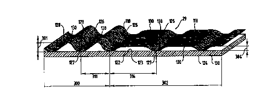
FIG. 1 illustrates a first embodiment of a multiple zone member according to
the
present invention, generally designated by the reference numeral 29. Generally
the
multiple zone member 29 comprises a sheet of loop material 118 having a
backing 120
preferably comprising a thermoplastic backing layer 122 (e.g., of
polypropylene) having
front and rear major surfaces 123 and 124, and a multiplicity of
longitudinally oriented
2o fibers in a specially formed sheet of fibers 126. Multiple zone member 29
comprises at
least two distinct zones. In the embodiment shown in Figure 1, the multiple
zone member
29 has a first zone 300 and a second zone 302. While Figure 1 shows a multiple
zone
member 29 having two distinct zones, multiple zone member 29 may have even
more
zones, e.g., 3, 4, 10, 1000, etc. Sheet of fibers 126 have anchor generally
non-deformed
anchor portions 127 bonded by being fixed to the backing layer 122 at spaced
elongate
generally parallel bonding locations 128 that are continuous in one direction
along the
front surface 123 with arcuate portions 130 of the sheet of fibers 126
projecting from the
front surface 123 of the backing layer 122 between the bonding locations 128
in
continuous rows also extending transversely across the sheet of loop material
118. While
CA 02326559 2000-09-29
WO 99/51429 PCT/US98/06560
8
the individual fibers in the sheet of fibers 126 may be of any size, the
individual fibers
preferably have denier in the range of 1 to 30.
Sheet of fibers 126 preferably has a hydrophilicity which is less than the
hydrophilicity of the backing 120. In a preferred embodiment, the sheet of
fibers
themselves have a hydrophilicity gradient wherein the arcuate portions 130
have a
hydrophilicity which is less than the hydrophilicity of the bonded locations
128. Even in
this configuration it is preferred that the bonded locations 128 of the sheet
of fibers 126
have a hydrophilicity which is less than the hydrophilicity of the backing
120.
Suitable materials for use as the backing 120 include but are not limited to
thermoplastic films, strips of thermoplastic film, porous films, apertured
films, apertured
formed films, unapertured formed films, nonwoven webs, strips of nonwoven
material,
hotmelt material, strips of hotmelt material, breathable materials, such as
breathable films,
including but not limited to microporous films, apertured nonwoven webs and
the like.
The backing 120 is preferably a relatively thin layer having a thickness in
the range of
about 0.00125 to 0.025 centimeters.
As can be seen in Figure 1, the arcuate portions 130 in the second zone 302
have a
height 304 from the backing 120 which is less than the height 301 of the
arcuate portions
130 from the backing 120 in the first zone 300. The arcuate portions 130 in
the first zone
300 have a generally uniform height 301 from the backing layer 122 of greater
than about
0.5 millimeters, preferably greater than about 1.0 millimeter, and more
preferably greater
than about 2.0 millimeters. Of course, the arcuate portions 130 in the first
zone 300 may
have even greater heights from the backing layer 122, e.g., heights of greater
than 3.0
millimeters or more.
As a result of the differences in the height of the arcuate portions within
the first
and second zones, the sheet of fibers 126 in the first zone 300 has a basis
weight greater
than the basis weight of the sheet of fibers 126 in the second zone 302. If
the backing 120 ,
is of the same basis weight in the first and second zones, the multiple zone
member 29
will then have a greater basis weight in the first zone 300 than in the second
zone 302.
The sheet of fibers 126 in the first zone 300 preferably has a basis weight in
the range of 5
CA 02326559 2000-09-29
WO 99/51429 PCT/US98/06560
9
to 300 grams per square meter (and more preferably in the range of I S to 100
grams per
square meter) measured along the first surface 123.
As can be seen in Figure 1 the spacing 311 between bonding locations 128 in
first
zone 300 is less than the spacing 314 between bonding locations 128 in the
second zone
302, i.e., the bonding locations are closer together in the first zone 300
than they are in the
second zone 302. However, the spacing 311 between bonding locations 128 in
first zone
300 may be the same, or greater than the spacing 314 between bonding locations
128 in
the second zone 302 as long as the multiple zone member 29 has the
aforementioned
height differences between the first zone 300 and the second 302.
The fibers in the sheet of fibers 126 can be disposed in various directions
with
respect to the parallel bonding locations 128 and may or may not be bonded
together at
crossover points in the arcuate portions 130; can be disposed in various
directions with
respect to the parallel bonding locations 128 with the majority of the fibers
in the sheet of
fibers 126 (i.e., over 80 or 90 percent) extending in directions at about a
right angle to the
bonding locations 128; or all of the individual fibers in the sheet of fibers
126 can extend
in directions generally at right angles to the spaced generally parallel
bonding locations
128.
The anchor portions 127 are preferably of such dimension that a planar circle
having a diameter of from about 0.2 millimeters to about 20 millimeters may be
inscribed
2o thereon, more preferably, the anchor portions 127 are preferably of such
dimension that a
planar circle having a diameter of from about 0.4 millimeters to about 10
millimeters may
be inscribed thereon, and most preferably, the anchor portions 127 are
preferably of such
dimension that a planar circle having a diameter of from about 0.8 millimeters
to about 5
millimeters may be inscribed thereon.
FIG. 2 illustrates a second embodiment of a multiple zone member according to
the present invention, generally designated by the reference numeral 140,
which multiple
zone member 140 has the same structure as the multiple zone member 29 (the
same
reference numerals being used with respect to the corresponding portions
thereof) except
that backing 14~ of the sheet of loop material 118 includes a second sheet of
backing
3o material 147, which second sheet of backing material 147 is adhered on the
side 124 of
CA 02326559 2000-09-29
. , . , ,
WO 99/51429 PCT/US98/06560
the backing layer 122 opposite the sheet of fibers 126. The second sheet of
backing
material 147 in the backing 145 of the sheet of loop material 118 may be a
polymeric
film. Other suitable materials for use as the second sheet of backing material
147 include
but are not limited to porous films, apertured films, apertured formed films,
unapertured
5 formed films, nonwoven webs, breathable materials, such as breathable films,
including
but not limited to microporous films, apertured nonwoven webs and the like.
The second
sheet of backing material 147 is preferably a relatively thin layer having a
thickness in the
range of about 0.00125 to 0.025 centimeters.
FIG. 3 illustrates a third embodiment of a multiple zone member according to
the
10 present invention, generally designated by the reference numeral 150, which
multiple
zone member 150 has the same structure as the multiple zone member 29 (the
same
reference numerals being used with respect to the corresponding portions
thereof) except
that backing 155 of the sheet of loop material 118 includes a plurality of
fibers 157.
Fibers 157 of backing 155 can be disposed in various directions with respect
to the
parallel bonding locations 128 and may or may not be bonded together; can be
disposed
in various directions with respect to the parallel bonding locations 128 with
the majority
of the fibers in the backing 155 (i.e., over 80 or 90 percent) extending in
directions at
about a right angle to the bonding locations 128; or all of the individual
fibers 157 in the
backing 155 can extend in directions generally at right angles to the spaced
generally
2o parallel bonding locations 128. Preferably, the individual fibers 157 are
not bonded
together and are spaced from one another by a distance of from about 0.01 mm
to about
10.0 mm. The fibers 157 have a denier within the range of about 0 - 50.
FIG. 4 is a top plan view of another embodiment of a fecal management member
202 of the present invention. Fecal management member 202 depicts one of many
possible configuration for the arrangement of the rows of arcuate portions
203.
FIG. 5 is a top plan view of another embodiment of a fecal management member
204 of the present invention. Fecal management member 204 depicts one of many
possible configuration for the arrangement of the rows of arcuate portions
205.
In addition to the configurations shown in FIGS. 4 and ~, other possible
configurations for the arrangement of the rows of arcuate portions may also be
used.
CA 02326559 2000-09-29
WO 99/51429 PCT/1JS98/06560
In another embodiment, the respective zones may have different configurations
for
the arcuate portions. For example, the first zone may comprise arcuate
portions as shown
in Figure 1, while the second zone comprises arcuate portions as shown in
Figure 4. Of
course, other combinations may also be used.
While the present invention has been described as a single material having two
distinct zones, it is also contemplated that one may achieve the same results
by bonding
together two materials each having the characteristics of the first and second
zones
respectively.
FIG. 6 schematically illustrates a method and equipment for forming the
multiple
to zone member 29. The method illustrated in FIG. 6 generally comprises
forming
longitudinally oriented polymeric fibers into a sheet of fibers 126, forming
the sheet of
fibers 126 so that it has arcuate portions 130 projecting in the same
direction from the
spaced generally parallel anchor portions 127 of the sheet of fibers 126, and
bonding the
spaced generally parallel anchor portions 127 of the sheet of fibers 126
projecting from
~5 the front surface 123 of the backing 120. This method is performed by
providing first and
second corrugating members or rollers 226 and 227 each having an axis and
including a
plurality of circumferentially spaced generally axially extending ridges 228
around and
defining its periphery, with the ridges 228 having outer surfaces and defining
spaces
between the ridges 228 adapted to receive portions of the ridges 228 of the
other
2o corrugating member 226 or 227 in meshing relationship with the sheet of
fibers 126
between the meshed ridges 228 and to afford rolling engagement between the
ridges 228
and spaces of the corrugating members in the manner of gear teeth. First and
second
corrugating members or rollers 226 and 227 may optionally be heated. The
corrugating
members 226 and 227 are mounted in axially parallel relationship with portions
of the
25 ridges 228 of the corrugating members 226 and 27 meshing generally in the
manner of
gear teeth; at least one of the corrugating members 226 or 227 is rotated; and
the sheet of
fibers 126 is fed between the meshed portions of the ridges 228 of the
corrugating
members 226 and 227 to generally conform the sheet of fibers 126 to the
periphery of the
first corrugating member 226 and form the arcuate portions 130 of the sheet of
fibers 126
3o in the spaces between the ridges 228 of the first corrugating member 226
and the
CA 02326559 2000-09-29 ~ , ,
WO 99/51429 PCT/US98/06560
12
generally parallel anchor portions 127 of the sheet of fibers 126 along the
outer surfaces
of the ridges 228 on the first corrugating member 226. The formed sheet of
fibers 126 is
retained along the periphery of the first corrugating member 226 after it has
moved past
the meshed portions of the ridges 228. The thermoplastic backing layer 120 is
formed and
bonded to the anchor portions 127 of the sheet of fibers 126 on the end
surfaces of the
ridges 228 on the first corrugating member 226 by extruding the thermoplastic
backing
layer 120 (e.g., polypropylene) in a molten state from a die 240 into a nip
between the
anchor portions 127 of the sheet of fibers 126 on the periphery of the first
corrugating
member 226 and a cooling roll 250 after which the multiple zone member 29 is
separated
1o from the first corrugating member 226 and carried partially around the
cooling roll 250
and through a nip between the cooling roller and a pinch roller 260 to
complete cooling
and solidification of the thermoplastic backing layer 120.
The sheet of fibers 126 fed between the meshed portions of the ridges 228 of
the
corrugating members 226 and 227 can be in the form of yarns distributed so
that the fibers
in the sheet of fibers 126 fed between the meshed ridges 228 of the
corrugating members
226 and 227 are uniformly distributed across the width of the sheet of fibers
i 26 and all
extend generally perpendicular to the axes of the corrugating members 226 and
227, or
the fibers in the sheet of fibers 126 can be disposed in random orientation as
in a non
woven web or sheet. Such a nonwoven sheet of randomly oriented fibers 126 with
no
2o internal bonding except for the friction between the fibers can be formed
from loose fibers
using a carding machine 270 as illustrated, which nonwoven sheet of randomly
oriented
fibers 126 has enough integrity to be fed from the carding machine 270 into
the nip
between the corrugating members 226 and 227 (if needed, a conveyer (not shown)
could
be provided to help support and guide the non woven sheet of randomly oriented
fibers
126 is used, preferably the first corrugating member 226 has a rough finish
(e.g., formed
by sand blasting), the second corrugating member 227 has a smooth polished
finish, and
the first corrugating member 226 is heated to a temperature slightly above the
temperature
of the second corrugating member 226 so that the nonwoven sheet of fibers 126
will
preferentially stay along the surface of the first corrugating member 226 and
be carried to
3o the nip between the first corrugating member and the cooling roller 250
after passing
CA 02326559 2000-09-29
WO 99/51429 PCT/US98106560
13
through the nip between the corrugating members 226 and 227. Alternatively,
instead of
feeding fibers from a carding machine 270, a sheet of bonded fibers, such as a
spunbond
web or other suitable web, may be fed from a roll to the corrugating members
226 and
227.
Corrugating members 226 and 227 adapted to have such a sheet of fibers 126 fed
into them can have their ridges 228 oriented generally in the range of 0 to 90
degrees with
respect to their axes, but preferably have their ridges 228 oriented at 0
degrees with
respect to (or parallel to) their axes which simplifies making of the
corrugating members
226 and 227.
to Instead of extruding a solid thermoplastic sheet 120 from die 240, a
plurality of
fibers may be extruded from a die to form a backing layer, such as backing
layer 1 SS
illustrated in FIG. 3.
Instead of extruding a thermoplastic material from a die such as die 240, a
non
molten backing maybe used. The roller 250 is then heated to thermo-bond the
backing to
the sheet of fibers.
As can be seen in Figure 6, rollers 226 and 227 each have a region
corresponding
to the first zone and second zones of the multiple zone material. Rollers 226
and 227
each have a first region 500 corresponding to first zone 300 and a second
region 502
corresponding to second zone 302. The dimension of the extending ridges 228 is
greater
2o in the first region 500 than in the second region 502. The spacing between
the ridges is
greater in the second region 502 than in the first region 500. Such a
configuration
produces the multiple zone member as shown in Figure 1.
FIG. 7 schematically illustrates another embodiment of a method and equipment
according to the present invention for forming the fecal management member
140, which
method is generally the same and uses much of the same equipment as is
illustrated in
FIG. 6 (with similar portions of that equipment having the same reference
numerals),
except for the addition of means including a pinch roller 340 for feeding the
sheet of
backing material 147 into the nip between the first corrugating roller 226 and
the cooling
roller 250 along the surface of the cooling roller 250 which results in the
extruded molten
3o thermoplastic backing layer 120 from the die 240 being deposited between
the formed
CA 02326559 2000-09-29
WO 99/51429 PCTNS98/06560
14
sheet of fibers 126 along the periphery of the first corrugating member 226
and the sheet
of backing material 120 along the surface of the cooling roll 250 so that the
molten
thermoplastic backing layer 120 envelopes and adheres the anchor portions 127
of the
sheet of fibers 126 to the sheet of backing material 147 after which the fecal
management
member 140 is separated from the first corrugating member 226 and carried
partially
around the cooling roll 250 with its backing 145 against the cooling roll 250
to complete
cooling and solidification of its thermoplastic backing layer 120. The molten
thermoplastic backing layer 120 can be extruded into the nip, onto the anchor
portions
127 of the sheet of fibers on the first corrugating member 226 prior to the
nip, or onto the
sheet of backing material 147 along the periphery of the cooling roller just
prior to the nip
as may work best for any given application. The cooling roll 250 can be water
cooled
and have a chrome plated periphery which is particularly useful for forming
the fecal
management member 140 because of the high rate of heat transfer such a cooling
roll 250
affords from the molten thermoplastic backing layer 120, through the sheet of
polymeric
backing material 147 and into the cooling roll 250. Alternatively, the cooling
roll 250
may have an outer rubber layer defining its surface which may be preferred for
forming
the fecal management member I40 if the sheet of backing material is of a
material (e.g.,
paper) that tends to restrict such heat transfer into the cooling roll 250,
whereupon the
rubber layer provides an alternative advantage of deforming adjacent its nip
with the first
corrugating roller 226 to provide intimate contact of the molten thermoplastic
backing
layer 120 with the anchor portions I27 of the sheet of fibers I 26 and the
sheet of backing
material 147.
The sheet of backing material l47 incorporated in the backing 145 could be a
woven, knitted, random woven, needle punched, nonwoven or other solid or
porous layer
of intertwined fibers, or could be a continuous polymeric film. Such film used
for the
sheet of backing material 21 may be a single layer of a polymeric material
such as
polypropylene, polyester, or polyamide; or may have a plurality of layers such
as a central
layer of a relatively high strength material such as polyester, a layer
defining the first
surface of a material more easily bonded to the layer of thermoplastic
material 120 such
as ethylene vinyl acetate or polyethylene, and a layer defining the outer
surface of the
CA 02326559 2000-09-29
WO 99/51429 PCT/US98/06560
backing 147 adapted to adhere the backing to a substrate such as polyethylene
or a
bonding layer of room-temperature non-tacky thermoplastic material. The sheet
of
backing material could also be a layer of pressure sensitive adhesive along a
release liner
disposed so that the release liner contacts the cooling roller 250, resulting
in the layer of
5 pressure sensitive adhesive being disposed along the rear surface of the
layer of
thermoplastic material 120 with the release liner over the layer of pressure
sensitive
adhesive and removable so that the pressure sensitive adhesive could be used
to adhere
the fecal management member to a substrate.
Preferably, the drives for the corrugating member 226 and 227 and for the
cooling
l0 roller 250 are separately controllable so that the cooling roller 250 can
be rotated at a
surface speed that is the same as or different than the surface speed of the
first corrugating
member 226. When the cooling roller 250 and the Frst corrugating member 226
are
rotated so that the cooling roller has a surface speed that is slower than the
surface speed
of the first corrugating member 226 the anchor portions 127 of the sheet of
fibers 126
15 will be moved closer together in the backing layer 120 at the nip between
the cooling
roller 250 and the first corrugating member 226, resulting in greater density
of the loop
portions 130 along the backing 120 than when the cooling roller 250 and the
first
corrugating member 226 are rotated so that they have the same surface speed.
In another alternative embodiment for making the multiple zone member to those
2o shown in Figures 6 and 7, the method and equipment may be the same as shown
in
Figures 6 and 7 except that the rollers 226 and 227 have just one region where
the spacing
and dimension of ridges 228 is uniform throughout the periphery of rollers 226
and 227.
The member produced with such a method will have arcuate portions which are
have the
same dimension. The member may then be subjected to selective stretching such
that a
portion thereof is elongated. The arcuate portions within the elongated
portion will have
a height dimension which is less than the height dimension of the arcuate
portions within
the non-elongated portion. Similarly, the spacing between the bonding
locations will be
greater in the elongated portion than in the non-elongated. The member may be
selectively stretched using known stretching techniques such as incremental
stretching
CA 02326559 2000-09-29
WO 99/51429 PCT/US98/06560
16
with corrugated stretching rollers, or other methods. Heat may also be used
during the
stretching operation.
Figure 8 is a plan view of the diaper 20 of the present invention in a flat-
out, state
with portions of the structure being cut-away to more clearly show the
construction of the
diaper 20. The portion of the diaper 20 which faces the wearer is oriented
towards the
viewer. As shown in Figure 8, the diaper 20 preferably comprises a liquid
pervious
topsheet 24; a liquid impervious backsheet 26; an absorbent core 28, which is
preferably
positioned between at least a portion of the topsheet 24 and the backsheet 26;
a fecal
management member 27 positioned between the topsheet 24 and the absorbent core
28;
l0 side panels 30; elasticized leg cuffs 32; an elastic waist feature 34; and
a fastening system
generally designated 40. Diaper 20 is shown in Figure 8 to have a front waist
region 36, a
rear waist region 38 opposed to the front waist region 36 and a crotch region
37 located
between the front waist region and the rear waist region. The periphery of the
diaper 20 is
defined by the outer edges of the diaper 20 in which the longitudinal edges 50
run
generally parallel to the longitudinal centerline 100 of the diaper 20 and the
end edges 52
run between the longitudinal edges 50 generally parallel to the lateral
centerline 110 of
the diaper 20.
The chassis 22 of the diaper 20 comprises the main body of the diaper 20. The
chassis 22 comprises at least a portion of the absorbent core 28 and
preferably an outer
2o covering layer including the topsheet 24 and the backsheet 26. If the
absorbent article
comprises a separate holder and a liner, the chassis 22 generally comprises
the holder and
the liner. (For example, the holder may comprise one or more layers of
material to form
the outer cover of the article and the liner may comprise an absorbent
assembly including
a topsheet, a backsheet, and an absorbent core. In such cases, the holder
and/or the liner
may include a fastening element which is used to hold the liner in place
throughout the
time of use.) For unitary absorbent articles, the chassis 22 comprises the
main structure
of the diaper with other features added to form the composite diaper
structure. While the
topsheet 24, the backsheet 26, and the chassis 22 may be assembled in a
variety of well
known configurations, preferred diaper configurations are described generally
in U.S.
3o Patent 3,860,003; U.S. Pat. No. 5,151,092; and U.S. Pat. No. 5,221,274
issued to Buell on
CA 02326559 2000-09-29
WO 99/51429 PCT/US98/06560
17
June 22, 1993. Other suitable diaper chassis design are disclosed in U.S. Pat.
No.
5,569,232; U.S. Pat. No. 5,554,144; U.S. Pat. No. 5,554; U.S. Pat. No.
5,554,145; U.S.
Pat. No. 5,556,394. Each of these references is hereby incorporated by
reference herein.
The backsheet 26 is generally that portion of the diaper 20 positioned
adjacent the
garment facing surface 45 of the absorbent core 28 which prevents the exudates
absorbed
and contained therein from soiling articles which may contact the diaper 20,
such as
bedsheets and undergarments. In preferred embodiments, the backsheet 26 is
impervious
to liquids (e.g., urine) and comprises a thin plastic film such as a
thermoplastic film
having a thickness of about 0.012 mm (0.5 mil) to about 0.051 mm (2.0 mils).
Suitable
1 o backsheet films include those manufactured by Tredegar Industries Inc. of
Terre Haute,
IN and sold under the trade names X15306, X10962 and X10964. Other suitable
backsheet materials may include breathable materials which permit vapors to
escape from
the diaper 20 while still preventing exudates from passing through the
backsheet 26.
Exemplary breathable materials may include materials such as woven webs,
nonwoven
webs, composite materials such as film-coated nonwoven webs, and microporous
films
such as manufactured by Mitsui Toatsu Co., of Japan under the designation
ESPOIR NO
and by EXXON Chemical Co., of Bay City, TX, under the designation EXXAIRE.
Suitable breathable composite materials comprising polymer blends are
available from
Clopay Corporation, Cincinnati, OH under the name HYTREL blend P18-3097. Such
2o breathable composite materials are described in greater detail in PCT
Application No.
WO 95/16746, published on June 22, 1995 in the name of E. I. DuPont and
copending
U.S. Patent Application Serial No. 08/744,487, filed on November 6, 1996 in
the name of
Curro. Other breathable backsheets including nonwoven webs and apertured
formed
films are described in U.S. Pat. No. 5,571,096 issued to Dobrin et al. on
November 5,
1996. Each of these references is hereby incorporated by reference herein.
The backsheet 26 may be joined to the topsheet 24, the absorbent core 28 or
any
other element of the diaper 20 by any attachment means known in the art. For
example,
the attachment means may include a uniform continuous layer of adhesive, a
patterned
layer of adhesive, or an array of separate lines, spirals, or spots of
adhesive. One
3o preferred attachment means comprises an open pattern network of filaments
of adhesive
CA 02326559 2000-09-29
WO 99/51429 PCT/US98/06560
l8
as disclosed in U.S. Patent 4,573,986 entitled "Disposable Waste-Containment
Garment",
which issued to Minetoia et al. on March 4, 1986. Other suitable attachment
means
include several lines of adhesive filaments which a:e swirled into a spiral
pattern, as is
illustrated by the apparatus and methods shown in U.S. Patent 3,911,173 issued
to
Sprague, Jr. on October 7, 1975; U.S. Patent 4,785,996 issued to Ziecker, et
al. on
November 22, 1978; and U.S. Patent 4,842,666 issued to Werenicz on June 27,
1989.
Each of these patents are incorporated herein by reference. Adhesives which
have been
found to be satisfactory are manufactured by H. B. Fuller Company of St. Paul,
Minnesota and marketed as HL-1258. Alternatively, the attachment means may
comprise
heat bonds, pressure bonds, ultrasonic bonds, dynamic mechanical bonds, or any
other
suitable attachment means or combinations of these attachment means as are
known in the
art.
The topsheet 24 is preferably positioned adjacent the body surface 47 of the
absorbent core 28 and may be joined thereto and/or to the backsheet 26 by any
attachment
means known in the art. Suitable attachment means are described above with
respect to
means for joining the backsheet 26 to other elements of the diaper 20. In one
preferred
embodiment of the present invention, the topsheet 24 and the backsheet 26 are
joined
directly to each other in some locations and are indirectly joined together in
other
locations by directly joining them to other elements of the diaper 20.
2o The topsheet 24 is preferably compliant, soft feeling, and non-irritating
to the
wearer's skin. Further, at least a portion of the topsheet 24 is liquid
pervious, permitting
liquids to readily penetrate through its thickness. A suitable topsheet 24 may
be
manufactured from a wide range of materials, such as porous foams; reticulated
foams;
apertured plastic films; woven or nonwoven webs of natural fibers (e.g., wood
or cotton
fibers), synthetic fibers (e.g., polyester or polypropylene fibers), or a
combination of
natural and synthetic fibers; or apertured nonwoven webs. If the absorbent
assemblies
include fibers, the fibers may be spunbond, carded, wet-laid, meltblown,
hydroentangled,
or otherwise processed as is known in the art. One suitable topsheet 24
comprising a web
of staple length polypropylene fibers is manufactured by Veratec, Inc., a
Division of
3o International Paper Company, of Walpole, Massachusetts under the
designation P-8.
CA 02326559 2000-09-29
WO 99/51429 PCT/US98/06560
19
Another suitable topsheet 24 is the multiple zone member 29 of the present
invention. Preferably, the first zone 300 of the multiple zone member 29 is
positioned in
the rear waist region 38 of the diaper 20 such that the first zone 300 is
aligned with the
wearer's anus where it can be most effective in the management of fecal
material
deposited onto the diaper 20. The second zone 302 is preferably positioned
within the
crotch region 37 and extend into the front waist region 36. In some
embodiments it may
also be desirable to have the first zone 300 extend from the rear waist region
38 into the
crotch region 37 either up to or just beyond the transverse centerline 110. Of
course, the
multiple zone member topsheet may be designed to any desired configuration,
such as, for
to male and female anatomies.
Suitable formed film topsheets are described in U.S. Pat. No. 3,929,135; U.S.
fat.
No. 4,324,246; U.S. Patent 4,342,314; U.S. Pat. No. 4,463,045; and U.S. Pat.
No.
5,006,394. Other suitable topsheets 30 are made in accordance with U.S. Pat.
Nos.
4,609,518 and 4,629,643. Such formed films are available from The Procter &
Gamble
Company of Cincinnati, Ohio as "DRI-WEAVE" and from Tredegar Corporation of
Terre
Haute, Indiana as "CLIFF-T."
The absorbent core 28 may comprise any absorbent material which is generally
compressible, conformable, non-irritating to the wearer's skin, and capable of
absorbing
and retaining liquids such as urine and other certain body exudates. The
absorbent core
28 may be manufactured in a wide variety of sizes and shapes (e.g.,
rectangular,
hourglass, "T"-shaped, asymmetric, etc.) and may comprise a wide variety of
liquid-
absorbent materials commonly used in disposable diapers and other absorbent
articles
such as comminuted wood pulp, which is generally referred to as airfelt.
Examples of
other suitable absorbent materials include creped cellulose wadding; meltblown
polymers,
including coform; chemically stiffened, modified or cross-linked cellulosic
fibers; tissue,
including tissue wraps and tissue laminates; absorbent foams; absorbent
sponges;
superabsorbent polymers; absorbent gelling materials; or any other known
absorbent
material or combinations of materials.
The configuration and construction of the absorbent core 28 may also be varied
(e.g., the absorbent cores) or other absorbent structures) may have varying
caliper zones,
CA 02326559 2000-09-29
WO 99/51429 PCT/US98/06560
a hydrophilic gradient, a superabsorbent gradient, or lower average density
and lower
average basis weight acquisition zones; or may comprise one or more layers or
structures). However, the total absorbent capacity of the absorbent core 28
should be
compatible with the design loading and the intended use of the diaper 20.
5 Exemplary absorbent structures for use as the absorbent assemblies are
described
in U.S. Patent 4,610,678; U.S. Patent 4.834,735; U.S. Patent 4,888,231; U.S.
Pat. No.
5,137,537; U.S. Patent 5,147,345; and U.S. Pat. No. 5,342,338. Each of these
patents is
incorporated herein by reference.
The fecal management member 27 is shown in Figure 8 to be positioned just
1o beneath the topsheet 24. Prefereably, the fecal management member is
positioned
between the topsheet 24 and the absorbent core 28. The fecal management member
27
may be secured to the topsheet 24 and/or the absorbent core 28. The fecal
management
member 27 preferably comprises the multiple zone member 29. Preferably, the
first zone
300 of the multiple zone member 29 is positioned in the rear waist region 38
of the diaper
t5 20 such that the first zone 300 is aligned with the wearer's anus where it
can be most
effective in the management of fecal material deposited onto the diaper 20.
The second
zone 302 is preferably positioned within the crotch region 37 and extend into
the front
waist region 36. In some embodiments it may also be desirable to have the
first zone 300
extend from the rear waist region 38 into the crotch region 37 either up to or
just beyond
2o the transverse centerline 110. Of course, the fecal management member may
be designed
to any desired configuration, such as, for male and female anatomies.
While particular embodiments of the present invention have been illustrated
and
described, it would be obvious to those skilled in the art that various other
changes and
modifications can be made without departing from the spirit and scope of the
invention.
It is therefore intended to cover in the appended claims all such changes and
modifications that are within the scope of this invention.