Note: Descriptions are shown in the official language in which they were submitted.
CA 02326593 2004-02-05
COUPLING SHOCK RESISTANT (CSR) COUPLER
FIELD OF THE INVENTION
The present invention relates, in general, to vehicular
type couplers and, more particularly, this invention relates to
robust, flexible type vehicular couplers that provide a
substantially equalized shear bolt load and preload under
conditions of unequal coupling forces.
BACKGROUND OF THE INVENTION
As is generally well recognized in the railway coupling
art, light rail vehicle (LRV) couplers make use of emergency
release bolts. These emergency release bolts extend radially
through a draft gear tube and into a hollow shank member
located behind and extending rearwardly from a coupling head.
Such hollow shank member contains an energy absorbing and
dissipation means. There is a coupling head disposed on a
first LRV car that engages and mechanically couples to a
coupling head disposed on a second LRV car. The draft gear
tube disposed on each respective car is mechanically secured to
the underside of its associated car.
Existing couplers normally employ a rigid hollow coupling
head shank portion suspended in a draft gear tube by radially
extending shear bolts. These shear bolts are designed to shear
and break in two when the coupling forces between two cars
which are coupled together exceeds a predetermined coupling
load limit, as provided by the strength of the shear bolts.
1
CA 02326593 2004-02-05
Normally, the coupling forces that occur when a train of
LRV cars is being assembled and connected together for travel
with a locomotive, or lead car, generally exert less load on
such shear bolts than the predetermined limit so that the
coupling shank/draft gear tube assembly remains intact.
In contrast thereto, hard couplings or collisions between
cars will exert loads in excess of the predetermined limit.
When this excess load occurs the bolts shear. This allows the
coupler shank portion to slide into the draft gear tube and
engage and compress the energy dissipation means located in the
draft gear tube. As is known in the art, such compression of
the energy dissipation means helps to absorb the energy of the
collision between the cars by deformation work.
In such existing couplers, the outside diameter of the
coupler shank portion is less than the inside diameter of the
draft gear tube in order to allow assembly of the two
components and travel of such coupler shank portion into the
draft gear tube during the above described collision couplings.
As such, the shear bolts effect suspension of the coupler
shank portion in the draft gear tube. The coupler shank
portion and an integral collar do not contact the inside
surface of the draft gear tube.
The shear bolts provide all the support for the coupler
shank portion and are unevenly loaded when the coupler heads of
two LRV cars do not contact each other squarely. An angled
contact of the face portions of the coupler heads tend to place
2
CA 02326593 2004-02-05
the majority of the contacting load on one side of the coupler
shank portion and on those shear bolts located on that side.
This occurrence can cause such shear bolts to shear prematurely
and fatigue more rapidly during normal car couplings.
The above and following description is directed to light
rail vehicle (LRV) type coupling, although it is believed the
principles of the present invention would be useful in coupling
other types of vehicles, particularly, passenger transit type
railway vehicles.
BRIEF SUMMARY OF THE INVENTION
The present invention solves the above described problem
of uneven coupling forces by providing a coupler tube shank
portion with longitudinal slots. Such longitudinal slots
permit the wall of the coupler tube shank portion to expand
outwardly and engage the inside surface of the draft gear tube
when radially extending shear bolts are threaded into the shank
wall. This arrangement will place the shear bolts in a
virtually pure shear configuration, while engagement of the
shank and draft gear walls help to equalize the loads during an
angled coupling to provide a more consistent emergency release
operation.
In addition, consistent emergency release shear bolt
operation is further enhanced by equalizing the torque applied
to the shear bolts when they are tightened in the process of
assembling the coupler shank portion and draft gear tube
components.
3
CA 02326593 2004-02-05
OBJECTS OF THE INVENTION
It is, therefore, one of the primary objects of the
present invention to provide an improved shock resistant
coupler which will substantially equalize uneven coupling
forces on shear bolts when vehicles are mechanically coupled
together.
Another object of the present invention is to provide an
improved shock resistant coupler in which such equalization is
achieved in a relatively low cost manner by simply
longitudinally slotting the tube of the coupler shank portion
to allow the walls of such tube to expand and engage the inside
surface of the draft gear tube.
Still another object of the present invention is to
provide an improved shock resistant coupler in which such
equalization can be enhanced by providing longitudinal relief
grooves in a collar that is located at the end of the coupler
head shank.
A further object of the present invention is to provide an
improved shock resistant coupler in which such slots and
grooves can be machined in the shank and collar portions or
they can be formed during casting of the shank and collar
portions.
Yet another object of the present invention is to provide
an improved shock resistant coupler that will equally preload
the release bolts when the coupler shank and draft gear tube
portions are assembled.
4
CA 02326593 2004-02-05
In addition to the various objects and advantages of the
present invention that have been discussed in some specific
detail above, various other objects and advantages of the
invention will become more readily apparent to those persons
who are skilled in the relevant art from the following more
detailed description of the invention, particularly, when such
description is taken in conjunction with the attached drawing
Figures and with the appended claims.
BRIEF DESCRIPTION OF THE DRAWINGS
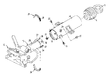
Figure 1 is an exploded, isometric view of the coupler
shank and draft gear assembly according to a presently
preferred embodiment of the invention;
Figure 2 is a top view, partially in longitudinal cross-
section, of the assembly illustrated in Figure 1; and
Figure 3 is a cross-sectional view of the assembly taken
along lines III-III in Figure 2 which illustrates the slots
provided in the coupler shank and in a collar of the coupler
shank, as well as relief grooves provided in the collar.
BRIEF DESCRIPTION OF A PRESENTLY PREFERRED EMBODIMENT
Prior to proceeding to the more detailed description of
the invention, it should be noted that identical components
having identical functions have been identified with identical
reference numerals throughout the several Figures illustrated
in the drawings, for the sake of clarity and understanding of
such invention.
CA 02326593 2004-02-05
Referring now to Figure 1 of the drawings, a coupler head
and a shank portion 12 of the coupler head 10 are
illustrated ready for assembly with a draft gear tube 14. The
assembly, preferably, is mechanically connected to the
underside of a vehicle (not shown) via a circular bushing 15.
Such circular bushing 15 is, also, connected to an energy
absorbing and dissipating means 16. Such energy absorbing and
dissipating means 16 is disposed for containment within the
draft gear tube 14. The draft gear tube 14 has, in addition, a
threaded mouth portion 18 located at the forward end of such
draft gear tube 14 for the purposes to be discussed in more
detail hereinafter.
Shank portion 12 is a substantially hollow tube-like
structure provided as an integral part of coupler head 10. The
shank portion 12 extends rearwardly from the coupler head 10
and is sized to fit into draft gear tube 14.
An integral collar member 20 is located at the distant end
of the shank portion 12, i.e., at the end of the shank portion
12 that is remote from the structure of the coupler head 10.
The integral collar member 20 is, also, sized to fit and extend
into such draft gear tube 14 and to engage the inside surface
of the draft gear tube 14 when a plurality of radially
extending shear bolts 22 are threaded into and through threaded
openings 24 provided in draft gear tube 14 and into threaded
holes 26 provided in integral collar member 20, in a manner
presently to be explained.
6
CA 02326593 2004-02-05
More particularly, the shank portion 12 and integral
collar member 20 are provided with at least two longitudinally
extending slots 28. These longitudinally extending slots 28,
preferably, form two resilient, flexible spring-like circular
wall portions 30 and two circular collar sections 32.
As can best seen in Figure 2, such longitudinally
extending slots 28 are shown diametrically opposed so that the
circular wall portions 30 are the same size and diametrically
opposed. The number of longitudinally extending slots 28 and
circular wall portions 30 are chosen to maintain the strength
and integrity of the shank portion 12 and integral collar
member 20 while at the same time providing a spring-like
resiliency to the circular wall portions 30.
In the process of threading shear bolts 22 into openings
26, shear bolts 22 pull the distal ends of wall portions 30 of
the shank portion 12 and the integral collar member 20 toward
the inside surface of such draft gear tube 14. With continued
rotation of shear bolts 22, the integral collar member 20 is
drawn into contact with and engages the inside surface of the
draft gear tube 14 thereby stabilizing the integral collar
member 20 and shank portion 12 within draft gear tube 14 and
placing the shear bolts 22 in a substantially pure shear mode.
The pure shear mode of the shear bolts 22 is further
assisted and assured by providing longitudinally extending
relief grooves 34 in such integral collar member 20. Such
longitudinally extending relief grooves 34 providing the
7
CA 02326593 2004-02-05
integral collar member 20 with additional flexibility for
disposition against the inside surface of the draft gear tube
14. As can be further seen in Figure 3 of the drawings, the
grooves 34 do not extend through the thickness dimension of the
integral collar member 20, as is the case with the
longitudinally extending slots 28.
In this manner, the integrity of the integral collar
member 20 is not compromised, yet the integral collar
member 20 has been given the enhanced capability to evenly seat
against draft gear tube 14 for a more even stress on shear
bolts 22.
In Figure 3, two grooves 34 are shown diametrically
opposed to each other and are located between the
longitudinally extending slots 28 at generally equal
circumferential distances and angles from such longitudinally
extending slots 28.
After the shank portion 12 is inserted into the draft gear
tube 14, in the process of assembling together the apparatus of
the invention depicted in Figure 1, a two piece ring or bushing
36 is disposed and secured together about the shank portion 12
and at a location between the integral collar member 20 and
such coupling head 10. The outside peripheral surfaces of the
two pieces of such ring 36 are threaded at 38 and are sized for
threading into the threaded mouth 18 of such draft gear tube 14
when the two pieces of the ring 36 are secured together.
8
CA 02326593 2004-02-05
The purpose of ring 36 is to keep the shank portion 12 in
the draft gear tube 14 after the shear bolts 22 are sheared
from the shank portion 12. This is effected in the present
invention by the integral collar member 20 abutting against the
ring 36. This allows the vehicle containing the apparatus of
the invention to be towed after such shear bolts 22 are sheared
in two, because the shank portion 12 will be prevented from
being pulled from such draft gear tube 14 by the ring 36.
The vehicle can be towed to a repair shop, for example,
for refitting the apparatus of Figure 1 with new shear bolts
22. The "stub" ends of broken bolts can be removed by hand or
by an "easy out" thread extractor. Tapped holes are not
damaged when the bolts break so that there is no need to re-
tap. In other words, the holes do not need to be retapped for
receiving new shear bolts 22.
The threaded ring 36 disposed in the threaded mouth 18 of
the draft gear tube 14 permits the ring 36 to be unscrewed from
such draf t gear tube 14 by use of a peg spanner wrench that
engage holes provided in the ring 36. This allows the shank
portion 12 and such integral collar member 20 to be removed
from the draft gear tube 14 for repair purposes.
When the integral collar member 20 is reconditioned, by
removing the release bolt studs, it and shank portion 12 are
re-inserted into draft gear tube 14 and new shear bolts 22 are
threaded through the openings 24 provided in the draft gear
tube 14 and into the openings 26 provided in the integral
9
CA 02326593 2004-02-05
collar member 20. Ring 36 is now returned to mouth 18 of the
draft gear tube 14, with assembly of the invention now being
ready for re-use in coupling vehicles together.
While a presently preferred embodiment of carrying out the
instant invention has been set forth in detail above, those
persons skilled in the vehicle coupling art to which this
invention pertains will recognize various alternative ways of
practicing the invention without departing from the spirit and
scope of patent claims appended hereto.