Note: Descriptions are shown in the official language in which they were submitted.
CA 02326646 2000-09-29
WO 99/62674 PCT/CA99/00~19
RATCHETING WRENCH
FIELD OF THE INVENTION
This invention relates to wrenches. More particularly, the invention relates
to open-
ended wrenches having heads which provide a ratchet-like action so that a
fastener may be
turned without disengaging the wrench from the head of the fastener.
BACKGROUND OF THE INVENTION
The prior art includes numerous different designs for open-ended wrenches
capable of
working with a ratcheting action. All of the prior art wrenches known to the
inventors have
one or more significant defects which limit their usefi~lness and have
prevented their
widespread adoption. A particular disadvantage of many prior ratcheting open-
ended
wrenches is that they are bulky. This makes them incapable of being used in
tight quarters.
SAE has defined an envelope within which open-ended wrenches should fit. The
SAE
envelope is described in the SAE Aeronautical Drafting Manual, and in
Machiner~r's
Handbook 23rd Edition. Industrial Press Inc., N.Y., N.Y., 1988 at page 1299.
In most cases it is impossible to make bulky prior art ratcheting open-ended
wrenches
compact enough to comply with the SAE specifications without rendering them
too weak to
use reliably. There is a need for simple effective ratcheting open-ended
wrenches which are
sufficiently compact to comply with the SAE specifications for open-ended
wrenches.
The prior art open-ended ratcheting wrenches also suffer from other
disadvantages.
Some designs are very complicated. Wrenches according to these designs are
undesirable
because they have many parts which can fail and are also expensive to make.
Other prior
wrenches are not sufficiently robust to turn a fastener with sufficient
torque. Other prior art
wrenches are awkward to engage with the head of a fastener. Other prior art
wrenches will not
properly grip fasteners which have rounded corners. Some prior art wrenches
will slip on a
fastener unless the fastener is completely bottomed in the wrench opening.
Prior inventors have struggled to provide open ended ratcheting wrenches
having fine
ratchet increments such as 45 degrees, 30 degrees, or even 15 degrees. A fine
ratchet
increment can allow fastener drive heads to be turned in tight quarters.
However, in the quest
for fine ratchet increments the designers of such previous wrenches have
sacrificed simplicity,
durability and usability. Most prior art wrenches which have a fine ratchet
increment cannot be
used reliably to turn fastener heads which have rounded corners. Furthermore,
most such
CA 02326646 2000-09-29
WO 99/62674 PCT/CA99/00519
2
wrenches cannot be used effectively unless they are held perpendicular to the
axis of rotation
of the drive head being turned.
Some prior art ratcheting wrenches have no moving parts at all. These wrenches
suffer
from the disadvantage that they do not work well on fasteners with rounded
corners. These
wrenches must have one very short jaw. Consequently they can be used
effectively only when
a fastener is fully bottomed in the wrench opening.
Gajo, U.S. patent No. 5,582,082 shows a ratcheting open ended wrench having a
moving jaw which both slides and pivots. This wrench is not as durable as
would be desirable.
The sliding action of the movable jaw can result in excessive wear.
Furthermore, the movable
jaw can become permanently deformed if the wrench is used aggressively. The
Gajo design
requires slots in the jaw which create areas of weakness.
There are a large number of prior wrenches capable of operating with a
ratcheting
action which include an opening defined by a movable jaw pivotally attached to
a fixed jaw. In
many of these wrenches, and in contrast to the wrench of this invention, the
movable jaw
rotates about a pivot point located on the same side of the opening as the
gripping surfaces of
the movable jaw. Some examples of such wrenches are Hewitt et al, U.S. patent
No.
2,277,400; Hesse, U.S. patent No. 1,050,215; Halstead et al, U.S. patent No.
770,574; U.S.
patent No. 4,324,159; Wylie, U.S. patent No. 5,018,412; Page, Canadian patent
No. 271,730;
De Santis, U.S. patent No. 4,554,847; and Meyer, U.S. patent No. 1,015,504.
There are a large number of prior ratchet type wrenches having two
independently
movable jaws. These wrenches are generally undesirably complicated and are
therefore
expensive to make. Furthermore, they have numerous parts which can wear out.
some
examples of such wrenches are disclosed in Bartlett, Canadian patent No.
519,086; Dyck,
Canadian patent Nos. 850,359 and 1,004,514; Dyck et al., U.S. patent No.
3,921,474;
Ginsburg, U.S. patent No. 1,183,371; Wilson, U.S. patent No. 3,878,741; Meggs
et al., U.S.
patent No. 4,065,986; Logan, U.S. patent No. 4,584,913; and Nitschmann, U.S.
patent No.
4,718,315.
Despite the wide variety of ratcheting open ended wrenches described in the
prior art
there remains a need for a compact open ended wrench which is capable of
providing a
ratcheting action and yet improves on the capabilities of prior art wrenches.
CA 02326646 2000-09-29
WO 99/62674 PCT/CA99/00519
3
SUMMARY OF THE INVENTION
This invention provides a ratcheting wrench for turning hexagonal drive heads
such as
the heads of bolts, nuts, pipe fittings, flare nuts, or other fasteners. The
wrench comprises a
handle having first and second ends. A fixed jaw projects forwardly from the
first end of the
handle. A movable jaw is pivotally attached to the handle. The movable jaw is
pivotally
movable relative to the fixed jaw about a pivot axis. The fixed and movable
jaws define an
opening between themselves. A hexagonal drive head can be received in the
opening between
first and second nut-contacting surfaces on the fixed and movable jaws
respectively. The first
and second nut-contacting surfaces are generally parallel when the movable jaw
is in a first
position. A stop member is located on the fixed jaw. A rearward face on the
stop member
provides an elongated stop surface located to block the movable jaw from
pivoting past the
first position toward the fixed jaw. A forward face on the stop member
provides a backstop
for blocking a drive head from being inserted into the opening past the
backstop. The wrench
also comprises bias means disposed between the handle and the movable jaw for
biasing the
movable jaw toward the fixed jaw. The first and second nut-contacting surfaces
are spaced
apart by a distance D when in the first position. The pivot axis is located on
a side of the first
nut-contacting surface away from the movable jaw and is located forwardly of a
rear edge of
the first nut contacting surface by a distance of at least 0.17XD.
Preferably the first nut-contacting surface has a recessed inside portion. The
recessed
portion extends from the backstop along the first nut-contacting surface for a
distance of at
least 0.35 X D and most preferably for a distance of at least 0.39 x D. Most
preferably the
recessed portion has a concave arcuate contour.
In some preferred embodiments the movable jaw comprises a pair of side plates
separated by a slot and the slot receives a web portion connecting the handle
and the fixed
jaw.
A flare-nut style wrench may be made according to the invention. In flare nut
style
wrenches according to the invention the fixed jaw comprises an extension
projecting
outwardly from the outer end of the first surface. The extension bears an
additional surface
inclined at an angle of 60 degrees to the first surface and a second recessed
portion between
the first and additional surfaces. A portion of the backstop is recessed to
permit back-rotation
of a drive head in the opening. Preferably the backstop comprises a flat
surface adjacent the
CA 02326646 2000-09-29
WO 99/62674 PCT/CA99/00519
4
second recessed portion. The flat surface is disposed at an angle of 60
degrees to the first
surface and can assist in driving a drive head engaged in the opening of the
wrench. Most
preferably the stop surface and the backstop are substantially coextensive.
BRIEF DESCRIPTION OF THE DRAWINGS
In drawings which illustrate specific embodiments of the invention, but which
should
not be construed as restricting the spirit or scope of the invention in any
way:
Figure 1 is an isometric view of an open-ended ratcheting wrench according to
the
invention;
Figure 2 is an exploded isometric view thereof;
Figure 3 is a longitudinal elevational sectional view through the ratcheting
head portion
thereof;
Figure 4 is a side elevational view of the ratcheting head portion thereof;
Figure 5 is a side elevational view of the ratcheting head portion thereof
engaging the
head of a fastener;
Figure 6 is a side elevational view of the ratcheting head portion thereof
during the
first few degrees of back rotation;
Figure 7 is a side elevational view of the ratcheting head portion thereof
toward the
completion of back rotation;
Figure 8 is a side elevational view of a ratchet head according to the
invention
illustrating the location of a pivot point relative to the face of a drive
head engaged by the
ratcheting head;
Figure 9 is the view of Figure 8 with the drive head partially withdrawn;
Figure 10 is an exploded isometric view of a wrench according to an
alternative
embodiment of the invention wherein a movable jaw pivots about an axis defined
by mating
dimples and protrusions;
Figure 11 is a partial sectional view through the ratcheting head of the
wrench of
Figure 10, when assembled;
Figure 12 is a side elevational view of the ratcheting head of a wrench
according to an
alternative embodiment of the invention wherein the backstop has a recessed
portion and the
movable jaw is relieved;
CA 02326646 2000-09-29
WO 99/62674 PCT/CA99/00519
Figure 13 is an isometric view of the ratcheting head end of a flare-nut type
wrench
according to the invention;
Figure 14 is an exploded view of the ratcheting head of the wrench of Figure
13; and,
Figure 15 is a side elevational view of the ratcheting head of the flare-nut
wrench of
5 Figure 13.
DETAILED DESCRIPTION
This invention provides ratcheting wrenches for turning drive heads, such as
the
hexagonal heads of nut, bolts, pipe fittings and the like. Wrenches according
to the invention
may be made in different forms. For example, open ended spanner-type wrenches
according to
some embodiments of the invention are illustrated in Figures 1 through 12. A
flare nut style
wrench according to an alternative embodiment of the invention is illustrated
in Figures 13
through 15.
Figure 1 shows a spanner type wrench 20 according to the invention. Wrench 20
has a
handle 22, a conventional box end wrench 24 on one end of the handle, and a
ratcheting open-
ended head 26 according to the invention at the opposite end of handle 22.
Handle 22 is
preferably reasonably thick so that it is comfortable to hold and reasonably
long so that a user
can apply torque to a drive head being turned by wrench 20 without excessive
effort.
Head 26 defines an opening 28 for receiving drive heads such as the heads of
nuts,
bolts or other fasteners equipped with suitably dimensioned hexagonal heads.
Head 26 permits
a fastener to be turned through a large angle without disengaging the fastener
from opening
28.
Preferably, opening 28 is symmetrical about a line which is parallel to the
axis of
handle 22. That is, head 26 preferably permits opening 28 to be engaged with a
fastener head
by moving wrench 20 in a direction parallel to the axis of handle 22. This
type of insertion is
called "inline" insertion. Inline insertion is desirable because it makes
wrench 20 easier to use.
When a wrench 20 is used to turn a fastener drive head then the direction of
rotation of
the fastener drive head can be reversed by simply flipping the wrench 20 about
its longitudinal
axis. If the wrench is configured for inline insertion then opening 28 will
automatically be
oriented properly to receive the fastener drive head, without changing the
orientation of the
axis of handle 22, when the wrench 20 is flipped. Some prior art wrenches are
designed in a
CA 02326646 2000-09-29
WO 99/62674 PCT/CA99/00519
6
way which does not permit inline insertion and which does not permit
modification for inline
insertion. Those skilled in the art will realize that while an inline
insertion configuration is
highly desirable, the angle of opening 28 relative to handle 22 in a wrench
according to the
invention may be varied without affecting the ratcheting action of head 26.
Head 26 has a movable jaw 30 which is pivotally affixed to a fixed jaw 32.
Movable
jaw 30 can pivot about a pivot axis 34. Pivot axis 34 is defined, for example,
by a pivot pin 36
which passes through holes in movable jaw 30 and fixed jaw 32. A rivet, screw,
press-in pin,
or the like could be used for pivot pin 36.
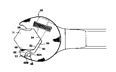
Fixed jaw 32 provides two nut-contacting surfaces 50, 52 (Fig. 5) for bearing
against two surfaces of the hexagonal drive head H of a fastener. Nut
contacting surface 50
may be termed a "first surface" . Nut contacting surface 52 may be termed a
"backstop" .
Nut-contacting surface 52 preferably includes a flat surface capable of
bearing against a
face of a drive head to help to grip and turn the drive head. Most preferably,
nut-contacting
surface 52 comprises a flat surface extending between nut-contacting surface
54 and recess
68 on nut-contacting surface 50.
Nut contacting surfaces 50 and 52 are disposed at an angle of 60 degrees to
one
another. Movable jaw 30 defines two additional nut contacting surfaces 54, 56
each also
capable of bearing against faces of the hexagonal drive head H. Nut contacting
surface 56
may be called a "second surface". Nut contacting surface 54 may be called a
"third
surface" . Nut contacting surfaces 54 and 56 are disposed at an angle of 60
degrees to one
another. Each of the nut contacting surfaces may be smooth, as illustrated, or
may be
serrated or otherwise textured to better grip a drive head. Opening 28 has an
internal shape
that generally follows 3'~Z sides of a regular hexagon when movable jaw 30 is
in its
"closed" position, as defined below.
Nut contacting surfaces 54, 56 on movable jaw 30 are on the opposite side of
opening 28 from pivot axis 34. This distinguishes wrenches according to this
invention
from wrenches of the type in which a movable jaw is pivoted on the same side
of the
opening as nut-contacting surfaces on the movable jaw.
As shown in Figure 2, movable jaw 30 preferably comprises a pair of side
plates 41
separated by a slot 38. Slot 38 receives the web 40 which connects fixed jaw
32 to handle
22. This arrangement provides a strong movable jaw 30 and prevents movable jaw
30 from
CA 02326646 2000-09-29
WO 99/62674 PCT/CA99/00519
7
twisting as torque is applied using ratchet head 26. Pivot pin 36 passes
through holes 37 in
side plates 41 and web 40. Movable jaw 30 is preferably fabricated in one
piece but may
comprise several pieces fastened together without departing from the
invention. Movable
jaw 30 should be strong so that it does not stretch significantly or become
otherwise
deformed during use.
As shown in Figure 3, a spring 42 extends between movable jaw 30 and web 40 so
that movable jaw 30 is biased to pivot away from handle 22 (i.e. movable jaw
is biased to
pivot in a counterclockwise direction when viewed as in Figure 3). Spring 42
is a
compression spring having first and second ends received in a cavity 46 in
movable jaw 30
and a recess 48 in web 40 respectively. Spring 42 lies within slot 38 and is
therefore
protected by side plates 41. A shutter portion 43 of movable jaw 30 is
preferably provided
to block dirt from entering the area around spring 42 from the outside end of
slot 38.
Spring 42 is located well away from pivot axis 34. One advantage of this
configuration is that a relatively light weight, spring 42 with a low spring
constant can
provide sufficient force to bias movable jaw 30 toward its "closed" position.
A second
advantage of this configuration is that recess 48 is located in a position
where it does not
unnecessarily weaken handle 22. Cavity 46 and recess 48 are preferably angled
slightly so
that spring 42 forms an arc, as shown. This helps to prevent spring 42 from
rubbing
excessively on side plates 41 and avoids jamming. The ends of spring 42 should
be squared
off so that spring 42 sits squarely in cavity 46 and recess 48.
As shown in Figure 4, the portion of fixed jaw 32 adjacent nut contacting
surface 52
defines an elongated, generally straight, stop member 59 which provides a pair
of stop
surfaces 60 on its rear side. One stop surface 60 projects outwardly on each
side of web 40.
Spring 42 biases movable jaw 30 into a "closed" position in which forward
surfaces of
plates 41 bear against stop surfaces 60. When movable jaw 30 is in its closed
position nut
contacting surfaces 52 and 54 are disposed at an angle of 60 degrees to one
another and
stop surfaces 60 prevent movable jaw 30 from rotating to further close opening
28. If
wrench 20 had no stop surfaces to prevent movable jaw 30 from closing too far
then great
forces would be applied to movable jaw 30 because of the close spacing between
pivot axis
34 and the portion of nut contacting surface 50 which bear against a drive
head being
turned by wrench 20. The handle then acts as a long lever arm which delivers
forces to
CA 02326646 2000-09-29
WO 99/62674 PCT/CA99/00519
8
movable jaw 30 through a very short lever arm. The resulting leverage could
cause
tremendous stresses in movable jaw 30 while wrench 20 is in use.
As described below, substantial forces are applied to stop surfaces 60 when a
fastener is being tightened. Providing extended stop surfaces 60, which bear
against the
forward surfaces of plates 41, distributes these forces over the extended
regions in which
plates 41 contact stop surfaces 60. Preferably stop surfaces 60 are
substantially coextensive
with nut contacting surface 52 as illustrated in Figure 4. This prevents
excessive contact
pressures which could wear or damage stop surfaces 60 or side plates 41.
Movable jaw 30
is readily able to bear forces applied to the forward surfaces of plates 41.
These factors
increase the ability of ratcheting head 26 to deliver large torques to
fasteners without
becoming damaged.
A portion 62 of fixed jaw 32 adjacent nut contacting surface 50 projects
outwardly
on each side from web 40. Portion 62 provides a concave arc-shaped face 62A on
each side
of web 40. Faces 62A each follow arcs centered on pivot axis 34. Faces 62A
matingly
receive arc-shaped faces 62B of ear portions 63 of plates 41. The mating of
faces 62B with
faces 62A prevents excessive shearing forces from being applied to pivot pin
36 when
wrench 20 is in use.
During tightening, drive head H exerts great forces which tend to separate
fixed jaw
32 and movable jaw 30. These forces would be applied to pivot pin 36 if it
were not for
mating faces 62A and 62B (Fig. 4). While torque is being applied to drive head
H, faces
62B bear against faces 62A. Mating faces 62A and 62B transmit these forces
directly from
movable jaw 30 to fixed jaw 32. The arcuate shape of surfaces 62A and 62B does
not
interfere with the ability of movable jaw 30 to pivot relative to fixed jaw
32.
The strength of pivot pin 36 could be increased by increasing the diameter of
pivot
pin 36. However, if wrench 20 is configured for inline operation then
increasing the
diameter of pivot pin 36 would unacceptably increase the bulk of wrench 20 so
that wrench
20 could no longer fall within the envelope set by the above-noted SAE
standards. Most
preferably, the wrench is constructed with a shape which conforms with SAE
wrench
specifications. In general, a smaller and more compact open-ended wrench is
better than a
larger more bulky wrench because it allows the wrench to be operated in
tighter quarters
than would be possible with a bulkier wrench.
CA 02326646 2000-09-29
WO 99/62674 PCT/CA99/00519
9
Figure 5 shows wrench 20 placed so that opening 28 receives a hexagonal drive
head H, such as the head of a bolt, nut or the like. Drive head H has four
faces F, G, F'
and G' which respectively contact nut contacting surfaces 50, 56, 52 and 54 of
ratcheting
head 26.
The size of drive head H which can be turned with ratcheting head 26 is
determined
by the distance D between nut contacting surfaces 50 and 56. Surfaces 50 and
56 are
spaced to slidingly receive parallel flats F and G of a hexagonal drive head
H. Simple
geometry shows that the length L of one side of a hexagonal drive head H
having a size so
that it can be snugly received between nut contacting surfaces 50 and 56 is
related to D by
the formula:
D ~ D
2 X sin(60 ° ) ~ 1.73
A wrench 20 may be provided in a range of sizes corresponding to various sizes
of standard
fastener heads.
The depth of insertion of drive head H into opening 28 is limited by nut
contacting
surface 52, which acts as a backstop. Nut contacting surface or "backstop" 52
bears against
face F' of drive head H when drive head H is fully inserted in opening 28 as
shown in
Figure 5.
The tip of movable jaw 30 adjacent nut contacting surface 56 is cut away as
compared to the tip of the conventional open-ended spanner wrench. Preferably
an angled
surface 66 extends past the outer end of nut-contacting surface 56. Surface 66
helps to
guide opening 28 onto a drive head H but is recessed sufficiently that it does
not interfere
with the ratcheting action of ratcheting head 26.
The outer end of nut-contacting surface 56 of movable jaw 30 is most
preferably
about 50% of the way along the flat G of drive head H which is adjacent to nut-
contacting
surface 56 when drive head H is fully received in opening 28. That is, when a
hexagonal
drive head having opposed flats of length L spaced apart by a distance equal
to D is fully
engaged in opening 28 then the outermost end of the nut-contacting surface 56
is at a
midpoint of flat G. In other words, the length L2 (Fig. 8) of nut-contacting
surface 56, as
measured from the position of corner Cl of a fully inserted, properly sized
drive head H,
CA 02326646 2000-09-29
WO 99/62674 PCTICA99/00519
is preferably about 0.5 xL (0.29 xD). A length longer than this is not
desirable as it could
interfere with back rotation. A shorter length is not desirable because the
tendency of
wrench 20 to slip on a drive head H increases as the length of nut-contacting
surface 56 is
reduced. The tendency for a wrench with a very short nut-contacting surface 56
to slip is
5 especially pronounced for drive heads H, such as worn bolts, which have
rounded corners.
Nut contacting surface 50 of fixed jaw 32 has a recess or "undercut" 68 in the
inner
portion of its face. Recess 68 is most preferably arcuate, as shown, and most
preferably
extends a distance LI (Fig. 8) of 0.67 xL (i.e. about 0.387 xD) from the
intersection of nut
contacting surfaces 50 and 52 (e.g. from the position of comer C3 of a fully
inserted,
10 properly sized drive head H) along the flat F of fastener drive head H.
Preferably distance
Ll is at least 0.35 xD and more preferably Ll is more than about 0.38 xD. If
LI is
significantly more than 0.39 xD then the ability of wrench 20 to grip a drive
head H is
reduced. This is particularly true if the drive head has rounded corners. If
LI is reduced too
far below its optimum value then smooth back rotation will be impeded. If LI
is further
reduced then a drive head H will bind in opening 28 during back rotation.
Recess 68 is deep enough to allow a drive head H to turn slightly in opening
28
during back rotation, as described below. Recess 68 should slope gently enough
into nut
contacting surface 50 that the corner of a drive head will not grab in recess
68 during
counter rotation.
The overall length of nut contacting surface 50, as measured from corner C3 of
drive head H (Figure 5) is preferably not significantly longer than L (D '-.
1.73). If nut-
contacting surface 50 were much longer than L, wrench 20 could not be operated
at an
elevated angle and still ratchet properly. The overall length of nut-
contacting surface 50
should not be significantly shorter than L (D-1.73) or wrench 20 will not be
able to tightly
engage drive head H.
When handle 22 is moved in the direction indicated by arrow 70, fastener drive
head H is turned clockwise (as shown in Figure 5) by the forces applied by nut
contacting
surfaces 50 - 56. As this is happening, the forces acting on movable jaw 30
tend to pull and
hold movable jaw 30 into firm contact with stop surfaces 60. As long as handle
22 is being
forced in the direction of arrow 70, head 26 operates in substantially the
same manner as a
conventional non-ratcheting open-ended spanner wrench.
CA 02326646 2000-09-29
WO 99/62674 PCT/CA99/00519
11
When handle 22 is moved in the direction of arrow 72 then corner C3 of drive
head
H can drop into recessed area 68 to allow ratcheting head 26 to counter rotate
with respect
to drive head H. As shown in Figure 6, recess 68 is deep enough to allow
ratcheting head
26 to counter rotate significantly in opening 28 while movable jaw 30 remains
in its
"closed" position against stop surfaces 60. When ratcheting head 26 is rotated
past the
position shown in Figure 6 then movable jaw 30 begins to open against the bias
forces
exerted by spring 42. The precise angle of back rotation at which movable jaw
30 begins to
open depends upon the length of nut-contacting surface 56, the geometry of
recess 68 and
the geometry of nut-contacting surface 52. Eventually movable jaw 30 pivots
until opening
28 is large enough to slip around head H as shown in Figure 7.
During back rotation, corner C2 of drive head H rides against nut contacting
surface 52. This tends to move drive head H outwardly in opening 28. Nut-
contacting
surface or "backstop" 52 prevents drive head H from moving deeper into opening
28 into a
position where it could jam against movable jaw 30.
Finally, after handle 22 has been moved in the direction of arrow 72 through
an
angle of approximately 60 degrees, movable jaw 30 is once again in a position
relative to
drive head H where spring 42 can bias it toward its closed position against
stop surfaces
60. Therefore, by alternately moving handle 22 in the directions of arrows 70
and 72, drive
head H may be rotated in a clockwise direction (as shown in Figure 5) without
the
ZO necessity of removing ratcheting head 26 from drive head H and re-engaging
ratcheting
head 26 with drive head H in a different orientation as would be required with
a
conventional open-ended wrench. If it is desired to tum drive head H in a
counter-
clockwise direction then it is only necessary to turn wrench 20 over.
The location of pivot axis 34 has a very significant effect on the operation
of
wrench 20. Pivot axis 34 should be located so that movable jaw 30 opens easily
during
back rotation, as described above.
Pivot axis 34 should also be located in a position wherein the forces on
movable jaw
keep movable jaw 30 in its closed position when a drive head H is being
tightened so
that movable jaw 30 will turn the drive head H without slippage. This
condition can be
30 satisfied by placing pivot axis 34 in a position which is significantly
forward from the
locations of comparable pivot axes in mast prior art wrenches.
CA 02326646 2000-09-29
WO 99/62674 PCT/CA99/00519
12
For example, Figure 8 shows a sharp cornered drive head H fully inserted in
opening 28. An angle Al, may be measured as shown in Figure 8, between a line
90
extending between corner Cl and pivot axis 34 and a second line 92
perpendicular to nut
contacting surface 50. Angle A1 determines how firmly movable jaw 30 will be
held closed
during tightening of a drive head H which has sharp corners and is fully
inserted into
opening 28 (so that the innermost part of nut-contacting surface 56 grips face
G of drive
head H). Increasing angle A1 increases the force components which tend to hold
movable
jaw 30 closed during tightening. In the preferred embodiment of wrench 20,
angle A1 is
about 10°. Most preferably angle A1 is 8° or more.
If drive head H has rounded corners or is not fully inserted into opening 28
or both
then the innermost part of nut-contacting surface 56 cannot grip drive head H.
In the worst
case, as shown in Figure 9, drive head H would be gripped only by the
outermost end of
nut-contacting surface 56. Figures 8 and 9 show an angle A2 measured between a
line 94
joining the tip of nut contacting surface 56 and pivot axis 34 and the second
line 92 (as
defined above to be a Line perpendicular to nut contacting surface 50). With
line 92 as a
reference, if "positive" angles are measured clockwise from line 92 then angle
A2 in
Figures 8 and 9 is a "negative" angle. That is, angle A2 measures a
counterclockwise
angular displacement of line 94 relative to line 92. When a drive head H is
gripped only at
the tip of movable jaw 30 then, if angle A2 is negative, as illustrated, the
forces on
movable jaw 30 tend to cause movable jaw 30 to open. Movable jaw 30 will begin
to open
under these circumstances if nut contacting surface 56 can slip on face G of
drive head H.
Whether nut contacting surface 56 will slip on face G of drive head H depends
upon
whether the angle at which surface 56 applies forces to drive head H is
greater or less than
the angle of static friction 6,. 8, is defined by the relationship:
6s = arctan(~) (2)
Where ~c is the static coefficient of friction between nut contacting surface
56 and face G of
drive head H. Many textbooks state that 8, for unlubricated steel surfaces
commonly used
to make wrenches and fastener drive heads is about -10 degrees. In practice
wrenches must
be considered to be lubricated because they are often coated with oils,
greases or the like.
The inventors' experiments have shown that 8, is typically about -5 degrees
for typical steel
CA 02326646 2000-09-29
WO 99/62674 PCT/CA99/00519
13
materials under various conditions of lubrication. At worst 9, is about -3
degrees. Figure
8 includes a line 96 which passes through pivot axis 34 at an angle of -3
degrees to second
line 92. In Figure 8 the angle of line 96 has been slightly exaggerated for
clarity.
From the foregoing it can be seen that the end of nut contacting surface 56
should
always be to the right of line 96 as shown in Figure 8. This ensures that
angle A2 will not
be more negative than -3 degrees. Consequently surface 56 will not slip on
face G even
under worst case conditions. If drive head H engages a portion of nut
contacting surface 56
further inside opening 28, as is desirable for best grip, surface 56 is even
less likely to slip
on face G. Under ideal conditions the point of contact between surface 56 and
face G is at
the innermost end of surface 56. It can be seen that the angle A1 between this
point and
pivot axis 34 is far to the right of line 96 so that slippage between nut
contacting surface 56
and face G cannot occur.
It is possible to maintain angle A2 so that it is not more negative than -3
° in a
wrench 20 according to the preferred embodiment of this invention because
pivot axis 34 is
located relatively far forward relative to opening 28 as compared to most
prior art
wrenches. As shown in the accompanying drawings angle A2 can be made
significantly
more positive than -3° in a wrench 20 according to the invention. Many
prior art wrenches
do not have this feature and cannot be modified in any evident way to provide
this feature.
Such wrenches will slip on a drive head unless the drive head is fully engaged
in the
opening of the wrench.
It has been found that a smoother action on back rotation results if
ratcheting head
26 can be counter rotated to a position where the outward end of nut-
contacting surface 56
can slip easily on face G of drive head H before movable jaw 30 begins to
open. To
achieve this, an angle A3 between a line 98 (Fig. 6) perpendicular to face G
and the line
94, which is defined above, should be significantly more negative than 6,. In
the preferred
embodiment of wrench 20 angle A3 is about -18 degrees.
If, as is the case in the embodiments illustrated herein, pivot axis 34 is
located close
to nut contacting surface 50 then the position of pivot axis 34 may be
specified by the
position at which line 92 through pivot axis 34 perpendicularly intersects the
line defined
by face F of a drive head positioned against nut-contacting surface 50. The
inventors have
determined that this intersection point should be located a distance L3 along
nut-contacting
CA 02326646 2000-09-29
WO 99/62674 PCT/CA99/00519
14
surface 50 in the range of 0.3 xL (about 0.17 xD) to 0.5 xL (about 0.289 xD)
as measured
from corner C3 of a properly sized hexagonal drive head H fully engaged in
opening 28.
Pivot axis 34 is preferably located at a distance in the range of 0.35 xL
(about 0.2 xD) to
0.45 xL {about 0.26 xD) along nut-contacting surface 50. Pivot axis 34 is most
preferably
located at a distance of about 0.39 xL (about 0.22 xD) along nut-contacting
surface 50.
It can be appreciated that moving pivot axis 34 outwardly along nut-contacting
surface 50 makes angle A2 less negative and results in wrench 20 being able to
better grip a
drive head H. Moving pivot axis 34 too far outwardly is not desirable,
however, because
angle A3, which affects the smoothness of back rotation, is made less negative
as pivot axis
34 is moved outwardly. Further, if pivot axis 34 is too far outwardly then
pivot pin 36 will
be located in an undesirably narrow portion of fixed jaw 32. Conversely, if
pivot axis 34 is
located too far back toward handle 22 then ratcheting head 26 will become
unable to
properly grip a drive head H, especially if drive head H is not fully inserted
into opening
28.
On wrenches according to the invention where angle A1 is small, it may be
necessary to slightly relieve nut contacting surface 54, as shown, for example
in Figure 12,
so that it does not contact drive head H when torque is being applied to drive
head H. If
nut-contacting surface 54 is maintained in tight contact with face G' of drive
head H then
face G' could press against nut-contacting surface 54 so as to open movable
jaw 30. On
wrenches where angle A1 is larger, nut contacting surface 54 can be allowed to
bear
against face G' to help to grip drive head H, in which case nut-contacting
surface 54 may
be termed a "third surface". In the preferred embodiment of wrench 20 it is
not necessary
for nut-contacting surface 54 to be relieved.
It can be appreciated that the wrench described herein is relatively simple to
manufacture and has only four parts. Handle 22 and fixed jaw 32 may be
fabricated as a
single part. Movable jaw 30 is a second part. The remaining parts are pivot
pin 36 and
spring 42. As described below, it is possible to replace the pivot pin by
appropriately
shaping the movable jaw 30 and the fixed jaw 32. This reduces to three the
number of parts
needed to fabricate a wrench according to the invention.
Figure 12 shows a wrench 120 according to an optional alternative embodiment
of
the invention. In wrench 120 an additional recess 168 is provided in nut-
contacting surface
CA 02326646 2000-09-29
WO 99/62674 PCT/CA99/00519
52. Recess 168 provides additional clearance to allow for back rotation of
ratcheting head
26 relative to a hexagonal drive head H. A wrench according to the invention
may have
one or more recesses 68, 168. Providing an additional recess 168 in nut
contacting surface
52 allows opening 28 of wrench 120 (Fig. 12) to rotate more nearly about the
same axis as
5 drive head H on back rotation than does opening 28 of wrench 20 of Figure 1.
Embodiments which include an additional recess 168 in nut contacting surface
52 can be
designed so that comer Cl can push against nut-contacting surface 54 near the
start of back
rotation to swing pivoting jaw 30 towards its open position when drive head H
is bottomed
. out against nut-contacting surface 52. This may result in a smoother action
on back
10 rotation. Of course, it is desirable that a wrench according to the
invention can also be used
to turn a drive head H which is not fully inserted into opening 28. Therefore,
a wrench
according to the invention should be designed bearing in mind the design
considerations
surrounding the angle of friction and angle A3 which are discussed above in
relation to
Figure 6. It is not usually desirable to provide an additional recess 168 in a
spanner type
15 wrench, such as wrench 20 of Figure 1 because an additional recess 168
tends to weaken
stop member 60. As noted above, stop member 60 can be subjected to large
loads. It is
desirable to keep stop member 60 robust.
Figures 13, 14 and 15 depict a flare nut style wrench 220 according to an
alternative
embodiment of the invention. Wrench 220 operates generally as described above.
In
wrench 220, fixed jaw 32 is extended to provide an additional nut-contacting
surface 250.
Additional nut-contacting surface 250 may be called an "additional surface" .
Wrench 220
provides more contacting faces and therefore has a better grip on fasteners,
than does the
standard spanner type wrench 20 described above. Nut contacting surfaces 50
and 56 can
be described respectively as first and second surfaces.
In addition to the recess 68 in nut contacting surface 50 wrench 220 has an
additional recess 168 in backstop 52 and a second additional recess, or
"second recessed
portion" 268 in additional nut-contacting surface 250. The three recesses 68,
168 and 268
allow the ratcheting head of wrench 220 to counter rotate around a drive head
H during
back rotation as described above. Preferably each of recesses 68, 168 and 268
have a
smooth arcuate contour. Preferably each of recesses 168 and 268 have a length
approximately equal to the length of recess 68 as described above.
CA 02326646 2000-09-29
WO 99/6264 PCT/CA99/00519
16
It can be appreciated that the forward position of pivot axis 34 helps to keep
movable jaw 30 closed during tightening of a drive head. This permits nut-
contacting
surfaces 250, 50, 52, 54 and 56 to all help to grip and turn a drive head
engaged in
opening 28. Of course, not all of these surfaces have the same ability to
drive a drive head
H. As is the case in a standard wrench 20 (Figure 4), nut contacting surfaces
50 and 56
have a greater capacity to drive drive head H than do nut contacting surfaces
52 or 54. In a
wrench 220 additional nut contacting surface 250 is opposed to nut contacting
surface 54
and therefore also has a reduced capacity as compared to nut contacting
surfaces 50 and 56.
It can also be appreciated that a drive head H can be inserted into opening 28
by
pushing the end of movable jaw 30 against the drive head until movable jaw 30
opens
enough to slip over the drive head. This is in contrast to standard fixed
flare nut wrenches
which must be slid axially over a drive head. A flare nut type wrench 220
according to the
invention may be made very compact.
While it is not necessary, a wrench according to the invention may be readily
made
to have all of its nut contacting surfaces equal in width. In particular, stop
member 59 is
configured so that nut contacting surface 52 can be made just as wide as the
other nut-
contacting surfaces. This is advantageous because it provides a larger area of
contact
between the various nut contacting surfaces and a drive head than would be the
case if
some nut contacting surfaces were much narrower than others. Furthermore, when
a
wrench has nut contacting surfaces 50, 52 and 56 which are equal in width, as
illustrated
by the preferred embodiments 20, 220 of Figures 1 and 13 respectively, then
the wrench
will work, as described above, even if the drive head H being turned is very
thin or if the
drive head H is gripped with the edges of the nut contacting surfaces only. In
preferred
embodiments of the invention, therefore, nut-contacting surfaces 50, 52 and 56
are all
equal in width. Most preferably, all nut-contacting surfaces in a wrench
according to the
invention are equal in width. Some prior art wrench designs do not provide nut-
contacting
surfaces which are equal in width.
As will be apparent to those skilled in the art in the light of the foregoing
disclosure, many alterations and modifications are possible in the practice of
this invention
without departing from the spirit or scope thereof. For example, pivot pin 36
could be
replaced with some other means for pivotally fastening movable jaw 30 to fixed
jaw 32.
CA 02326646 2000-09-29
WO 99/62674 PCT/CA99/00519
17
One way to do this is to provide opposed projections 36A on either side of web
40 and to
provide corresponding dimples, recesses or holes 36B on the inward faces of
side plates 41
as shown in Figures 10 and I 1. Movable jaw 30 could then be assembled to
fixed jaw 32
by spreading side plates 41, positioning dimples 36B over projections 36A and
allowing
projections 36A to snap into dimples 36B. This arrangement will still be
strong enough to
work reliably because most of the forces acting between fixed jaw 32 and
movable jaw 30
are transmitted directly between faces 62B and faces 62A as described above.
In the
alternative to having dimples 36B in side plates 41 and projections 36A in web
40, dimples
36B could be in web 40 and projections 36A could be on side plates 41.
In cases where it is not necessary to provide a wrench which conforms with SAE
specifications, a wrench according to the invention could be made with a pin
36 large enough
to transmit all of the forces generated during use between movable jaw 30 and
fixed jaw 32.
By rotating head 26 relative to handle 22 the pin could be located in a strong
part of the
handle. In this case mating bearing faces 62B and 62A would not be necessary.
Other bias means may be provided in place of spring 42 to cause movable jaw 30
to
pivot toward its closed position. For example, a leaf spring, a resilient
bumper, a differently
arranged compression spring or a tension spring could be used in place of
compression spring
42.
Instead of being equipped with a long handle 22 as shown in the drawings head
26
could be attached to a very short handle equipped with a socket to provide a
ratcheting crow-
foot type wrench.
Movable jaw 30 has been illustrated and described as being of sufficient
length that
nut-contacting surface 56 extends half way along the flat G of head H when
head H is filly
inserted into opening 28. That is, nut-contacting surface 56 has a length of
approximately
0. 5 xL (or 0.3 xD). Nut-contacting surface 56 could be made somewhat shorter
than this.
However, if nut-contacting surface 56 is too short then it will no longer
adequately grip a
drive head H if the corners of drive head H are rounded. Nut-contacting
surface 56 could be
made slightly longer than this. However, if it is too long then drive head H
may become
jammed during back-rotation.
Recesses 68, 168, and 268 have been illustrated and described as being arc-
shaped.
The shape and depths of recesses 68, 168 and 268 could be varied without
affecting the
CA 02326646 2000-09-29
WO 99/62674 PCT/CA99/00519
18
operation of a wrench according to the invention as long as they allow
sufficient back rotation
of ratcheting head 26 relative to a drive head H and do not catch the corners
of the drive head
H as it turns.
Accordingly, the scope of the invention is to be construed in accordance with
the
substance defined by the following claims.