Note: Descriptions are shown in the official language in which they were submitted.
CA 02326980 2000-11-28
Doc. No. 10-304 CA Patent
Low Cost Amplifier Using Bulk Optics
Field of the Invention
This invention relates generally to optical amplifiers and more particularly,
to an in-line
optical amplifier that can be coupled to optical fibre, wherein the amplifying
medium has
a substantially larger mode field diameter than the optical fibre to which it
is coupled.
Background of the Invention
to
There is considerable interest in using rare earth doped fiber amplifiers to
amplify weak
optical signals for both local and trunk optical telecommunications networks.
The rare
earth doped optical amplifying fibers exhibit low-noise, have relatively large
bandwidth
with low polarization dependence, substantially reduced crosstalk problems,
and low
insertion losses at the relevant operating wavelengths which are used in
optical
communications. Furthermore, rare earth doped optical fiber amplifiers can be
coupled
end-to-end to a transmission fiber, and coupled, through a directional
coupler, to a laser
diode pump. The directional coupler is designed to have a high coupling ratio
at the pump
wavelength and a low coupling ratio at the signal wavelength so that maximum
pump
energy is coupled to the amplifier with minimal signal loss. When the
amplifying
medium is excited with the pump laser, signal light traversing the amplifier
experiences
gain. The pump energy may be made to propagate either co-directionally or
counter-
directionally relative to the signal energy, selected for higher power
efficiency or better
noise performance
To date, erbium fiber amplifiers appear to have the greatest potential for the
high
amplification necessary to overcome the signal losses. Erbium doped fiber
amplifiers
(EDFAs) operate at 1550 nm which is of particular interest for optical
communication
systems because, in this wavelength region, the amplifiers exhibit low
insertion loss,
3o broad gain bandwidth (approximately 30 nm) and relatively polarization
insensitive gain.
Such amplifiers, pumped with light having a wavelength of 980 nm can have a
gain as
CA 02326980 2000-11-28
Doc. No. 10-304 CA Patent
high as 26 dB but require as much as 76 mW of launched pump power. It has
generally
been desired to achieve a higher gain together with a lower value of pump
power coupled
into a fiber, and such optimization of EDFAs has been a goal. The pump
required to
launch a signal into a single mode fibre is quite costly.
The present invention has realized a design to utilize a very high power pump
launching a
multimoded signal having approximately 1 W of pump power. Currently, high
power
optical pump lasers are commercially available at a relatively low cost. Such
high power
pumps are not compatible for use with erbium doped fibre in the manufacture of
EDFAs.
However, this invention provides a relatively inexpensive optical amplifier
that is
compatible for use in an optical fibre telecommunications system or for other
uses.
This invention also provides a device that does not require unwieldy lengths
of erbium
doped fibre to form an amplifier. In contrast, the instant invention uses a
block of glass
having a mode field diameter orders of magnitude larger than the mode field
diameter of
erbium doped fibre.
By enlarging the mode field of the signal beam, greater pump energy can be
applied
without the significant difficulty and loss which are present when coupling
pump energy
2o into a single mode fiber amplifier.
By using a block of glass having a rare earth therein, packaging, temperature
stabilizing
and temperature tuning of the amplifier become practicable.
Furthermore, a cylindrical block of glass having planar ends, lends itself to
applying
coatings or filters thereto, thereby forming selective filters at ends of the
erbium doped
block to allow the pump light in, and the signal light in at opposite ends,
while preventing
light at the pump wavelength to propagate out with the amplified signal.
2
CA 02326980 2000-11-28
Doc. No. 10-304 CA Patent
Summary of the Invention
In accordance with the invention there is provided, an optical amplifier
comprising: an
optical waveguide for carrying an optical signal to be amplified, the optical
waveguide
having an output end for outcoupling the optical signal;
a substantially collimating lens optically coupled with the output end of the
optical
waveguide for receiving the optical signal and for providing a substantially
collimated
beam to be amplified, the substantially collimated beam having a substantially
larger
mode field diameter than the optical signal being carried by the optical
waveguide;
1 o a block of light transmissive material sized to carry the substantially
collimated beam for
amplification, the block of light transmissive material being comprised of a
gain medium
doped with a rare-earth element, the block being disposed to receive the
substantially
collimated optical beam; and,
a high power pump disposed to impart optical energy to the block; and, an
output optical
waveguide disposed to couple focused light of the optical signal after it has
been
amplified within the block of light transmissive material.
In accordance with the invention there is further provided, an optical
amplifier
comprising: a first optical waveguide for providing a signal to be amplified,
the
2o waveguide having an average mode field diameter d,;
a second optical waveguide optically coupled with the first waveguide for
receiving the
signal after it has been amplified, the second waveguide having a mode field
diameter d2,
where d i and dZ are substantially smaller than d3;
a light transmissive amplifying medium for guiding a beam having a mode field
diameter
of at least d3, said light transmissive amplifying medium being disposed to
receive light
from the first optical waveguide and to provide amplified light to the second
optical
waveguide;
a pump optically coupled with the light transmissive amplifying medium for
providing
pump energy to the amplifying medium.
CA 02326980 2000-11-28
Doc. No. 10-304 CA Patent
In accordance with the invention there is further provided, an optical
amplifier for
amplifying an incoming optical signal comprising a glass block in the form of
a light
transmissive medium sized to carry a beam having a mode field diameter of at
least
1 OO~m, the block being doped with a rare earth for amplifying light passing
therethough
when the rare earth is excited by a pump beam, the light transmissive medium
having a
filter at an end thereof for passing the pump beam and for substantially
preventing the
optical signal to be amplified from passing therethrough, and having a filter
at another
end thereof, for passing the signal to be amplified and for substantially
preventing the
pump beam from passing therethrough.
l0
In accordance with the invention there is provided, an optical amplifier
comprising:
an input optical fibre for providing a signal to be amplified;
an amplifying medium comprising a light transmissive material having a
diameter
substantially greater than the diameter of the input optical fibre, for
receiving the signal
~ 5 to be amplified;
a lens for substantially expanding a mode field diameter of a beam of light of
the signal
to be amplified, optically coupled between the input waveguide and the
amplifying
medium;
a pump source for providing high intensity optical pump energy to the
amplifying
2o medium; and,
an output optical fibre for receiving an amplified optical signal from the
amplifying
medium.
In accordance with another aspect of the invention a method of amplifying an
optical
35 signal is provided, comprising the steps of:
coupling the optical signal from an optical fibre into an amplifying medium
having a
diameter a plurality of orders of magnitude greater than a mode field diameter
of the
signal propagating with the optical fibre such that the mode field diameter of
the signal is
converted to a substantially larger collimated beam than the signal
propagating with the
3o optical fibre;
CA 02326980 2000-11-28
Doc. No. 10-304 CA Patent
pumping optical energy having a different wavelength from the optical signal
into the
amplifying medium, and receiving the amplified optical signal from the
amplifying
medium.
In accordance with the invention there is further provided, a method of
amplifying an
optical signal comprising the steps of:
launching a beam carrying the optical signal from an optical fibre;
substantially increasing a mode field diameter of the beam and providing the
beam to an
amplifying medium;
pumping optical energy having a different wavelength from the optical signal
into the
amplifying medium, and receiving an amplified optical signal from the
amplifying
medium and,
decreasing the mode field diameter of the amplified signal and coupling the
amplified
signal to an output optical fibre.
Brief Description of the Drawings
Exemplary embodiments of the invention will now be described in conjunction
with the
drawings in which:
2o Fig. 1 is a conventional erbium doped fibre optical amplifier;
Fig. 2 is a schematic illustration of an amplifier in accordance with the
present invention;
Fig. 3 is a schematic illustration of an alternative embodiment of the present
invention;
Fig. 4 is a schematic illustration of an alternative embodiment of the present
invention in
which the amplifying medium has optical power;
Fig. 5 is a schematic view of the amplifying medium illustrating angular
separation of
input and output signals;
Fig. 6a is a schematic view of the amplifying medium illustrating total
internal reflection
of the pump signal;
Fig. 6b is a schematic view of the amplifying medium illustrating a collimated
pump
signal; and
5
CA 02326980 2000-11-28
Doc. No. 10-304 CA Patent
Fig. 7 is a schematic illustration of a further embodiment of the present
invention in
which the amplifying medium is enlarged to accommodate a plurality of input
and output
fibres.
Detailed Description
Rare earth doped fibers for amplifying weak signals for both local and trunk
optical
telecommunications networks have been of interest for some time now, because
of their
low insertion loss, broad gain bandwidth and low polarization sensitivity. In
use, the
i o doped optical fiber is normally coupled to a pump so that a weak optical
input signal at
some wavelength within the rare earth gain profile experiences a desired
amplification.
Pump light which can be coupled into the optical fiber via a directional
coupler may
propagate either co-directionally or counter-directionally within the fiber
relative to the
signal. The directional coupler can have a high coupling ratio at the pump
wavelength
I 5 and a low coupling ratio at the signal wavelength.
When the fiber is not pumped, the signal experiences loss due to ground state
absorption
by the rare earth ions. As the pump power that is applied to the fiber is
increased, the loss
due to ground level absorption decreases (i.e., gain is negative but
increasing) until, at
2o some value of pump power, there is no net signal absorption (i.e. the gain
is zero). This is
referred to as the transparency state. Thereafter, as the pump power in the
fiber is
increased, a higher proportion of rare earth ions are in their excited state
and the
stimulated emission from the upper lasing state to the ground state becomes
stronger than
the absorption from the ground state to the upper lasing state, resulting in a
net positive
25 gain at various wavelengths. Thus, the optical amplifier, when pumped so as
to populate
the upper lasing level, produces a net positive gain above the pump threshold
level and
the fiber acts as an amplifier.
Pumping is effected by a separate laser or lamp which emits photons of an
appropriate
3o energy which is higher than that which corresponds to the signal
wavelength. The
electrons are excited from the ground state to one or more pump bands, which
are above
6
CA 02326980 2000-11-28
Doc. No. 10-304 CA Patent
the upper lasing level. It is important that the spontaneous lifetime of the
upper lasing
level exceed that of the pump bands by a significant margin to allow heavy
population of
the upper level. When a photon at the laser wavelength interacts with an
excited ion in
the upper lasing state, stimulated emission can occur. The photon can come
from either
previous spontaneous emission, stimulated emission, or an input signal.
This invention utilizes a cylindrical block of erbium doped glass as an
amplifying
medium. In contrast to erbium doped optical fibre amplifiers, the cylindrical
block has a
cross section orders of magnitude greater than the cross section of optical
fibre.
1 o Furthermore a very high power pump laser is utilized to provide a required
amount of
energy to the erbium-doped block. Essentially, the mode field diameter of a
beam
propagating within an optical fibre is expanded to propagate through and
traverse the
cylindrical block.
~ 5 Turning now to Fig. 1, a prior art erbium doped optical fibre amplifier 10
is shown
having a pump 12 coupled with an incoming optical signal 20 to be amplified. A
laser
diode 12 provides an output signal having a wavelength of 980 nm that is
coupled with an
incoming signal 20 to be amplified having a wavelength of 1550 nm. A laser
diode pump
at 1480 nm can alternatively be used. A coupler 14 couples the two signals
together to be
20 output on a suitable length of erbium doped optical fibre 16.
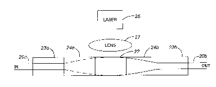
Turning now to Fig. 2, a block of glass 22 in the form of a rod having a
diameter of
approximately 350 ~m is shown; the block 22 is doped with erbium. A suitable
glass is
commercially available under the name MM-2, an erbium doped phosphate laser
glass
25 produced by Kigre, Inc.. This material includes high dopant percentages and
provides
high gain. A typical length of block 22 required for a net gain of 20 dB is in
the range of
1 cm. Notwithstanding, the overall performance depends upon many variables;
the same
physical principles used in current optical fiber based amplifiers apply. The
block 22 is
disposed between two substantially quarter pitch GRIN lenses 24a and 24b which
are
3o disposed between two optical fiber sleeves 23a and 23b housing input
optical fibre 20a
and output optical fibre 20b. In operation, light to be amplified of a
wavelength of
7
CA 02326980 2000-11-28
Doc. No. 10-304 CA Patent
approximately 1550 nm is launched into optical fiber 20a and is output on
optical fibre
20b. After the light enters the GRIN lens 24a it is collimated and the mode
field of the
beam is expanded to a diameter that can be supported by the erbium doped glass
block
22. Hence the beam diameter is expanded to occupy most of the block 22, as it
traverses
the block. Simultaneously a laser 25 optically coupled with the block 22
having a
wavelength of 980 nm outputs and pumps the block medium 22 with a high power 1
watt
signal that is distributed across and into the block by the lens 27 disposed
between the
block 22 and the laser 25. As the signal passes through it gains energy from
the excited
medium 22 and becomes amplified. The mode gain of the medium is calculated by
the
~ o following equations:
G=exp(g~L)
g=a~N
where g is the gain coefficient, L is the length of the gain medium, and a is
the emission
cross section, and N is the Er3+ ion density. Conditions of strong inversion
with high
pump power are assumed for the calculation. The resulting gain coefficient can
reach 22
dB/ cm, given an Er3+ concentration of IOZ~ cm~3, and emission cross section
of 5 x 10 ~2~
cm2.
Referring now to Fig. 3, a preferred embodiment of the invention is shown,
wherein both
input and output optical fibres are coupled into the same end of the device.
This type of
arrangement is preferred and offers advantages when providing hermetic
devices. A
block 22 similar to the one shown in Fig. 2 is provided having a first optical
filter 34 and
a second optical filter 32 at opposing ends. The filter 34 is designed to pass
light having
a wavelength of 1550 nm while reflecting light having a wavelength of 980 nm
generated
by the pump laser. Conversely, the filter 32 is designed to pass light having
a wavelength
of 980 nm and reflect light incident thereon having a wavelength of 1550 nm.
The pump
laser 38 is optically coupled to the erbium doped block 22 via a lens 24b.
Both input and
output optical fibres 30a and 30b respectively are disposed with an optical
fibre ferrule 23
8
CA 02326980 2000-11-28
Doc. No. 10-304 CA Patent
and are coupled optically coupled to the block of rare earth doped medium 22
via a light
transmissive spacer element 36 and a GRIN lens 24a. For optimum coupling, it
is
preferred that the optical path length of the spacer is equal to the optical
path length of
the block 22, such that the beam traversing both elements traverses equal path
lengths.
s
In operation, a signal light having wavelength 1550 nm is launched from input
optical
fibre 30a and is collimated to a substantially larger beam with a
substantially larger mode
field diameter as it traverses the GRIN lens 24a. The light then passes
through the filter
34 and enters and substantially fills the erbium doped block of glass 22.
Simultaneously,
~ o the high power laser 38 provides a pump signal having a wavelength of 980
nm to the
block 22 after being substantially collimated by lens 24b. Amplified light
having a
wavelength of 1550 nm is reflected by filter 32 and passed through the filter
34 to couple
into the output fibre 30b.
~ 5 If the rare earth doped block 22 is dimensioned to absorb substantially
all the pump
energy, the filter 34 is not necessary. In addition, the pump laser 38 can be
coupled
through a different lens, than a GRIN lens, or no lens at all. In particular,
the rare earth
medium 22 can be formed with a taper to a 100 micron diameter and coupled
directly to
the laser 38.
In addition to filters 34 and 32 at the end surfaces of the block 22,
advantageously in
accordance with the present invention, additional optical elements can be
formed on the
block 22, such as diffraction elements or additional filters, or lenses, by
etching,
depositing or adhering to the end faces of the block 22. Input fibres 20a, 30a
and output
fibres 20b, 30b can advantageously be polarization maintaining fibre pigtails
to provide a
polarization maintaining amplifier.
An alternative embodiment of the invention is shown in Fig. 4 wherein two
quarter pitch
focusing/collimating glass GRIN lenses are doped with erbium and form an
optical
amplifier. A first GRIN lens 44a is coated on an input/output end with a 1550
nm
3o bandpass filter 54; at an opposite end of the lens is a coating 52 that
serves as a 980 nm
bandpass filter. A second lens 44b is disposed directly against the filter 52.
At an
9
CA 02326980 2000-11-28
Doc. No. 10-304 CA Patent
outwardly facing end of the second GRIN lens 44b is a laser pump 38; The
operation of
this device is substantially the same as the amplifier described in Fig. 3,
however
amplification takes place inside the lens.
s Fig. 5 illustrates the input signal 30a and output signal 30b launched at a
small angle, for
instance of approximately 1.5 degrees in order to easily separate the input
signal from the
output signal.
As shown in Figs 6a and 6b, the amplifying medium 122 can be formed to provide
1 o waveguiding for the pump energy without guiding the signal Coating the
block 22, for
example with a metal cladding 120 will keep pump light within the block to
assist in
inducing the maximum pump light absorption. With the pump source 38 coupled
directly
to the metal cladded block 122 total internal reflection causes the pump light
to reflect
from the sidewalk within the block 122. As shown in Fig. 6b, with a
collimating lens
I S 124 coupling the laser pump 38 to the block 122, an expanded beam of pump
light is
launched through the medium 122.
Of course, due to the symmetry of a GRIN lens, multiple groups of input and
output
fibres 130, 230 can be disposed to amplify more than one signal at a time, as
shown in
2o Fig. 7. A larger block diameter is required to prevent the multiple signal
beams from
overlapping and interacting within the block 222.