Language selection

Search

Patent 2327848 Summary

Third-party information liability

Some of the information on this Web page has been provided by external sources. The Government of Canada is not responsible for the accuracy, reliability or currency of the information supplied by external sources. Users wishing to rely upon this information should consult directly with the source of the information. Content provided by external sources is not subject to official languages, privacy and accessibility requirements.

Claims and Abstract availability

Any discrepancies in the text and image of the Claims and Abstract are due to differing posting times. Text of the Claims and Abstract are posted:

  • At the time the application is open to public inspection;
  • At the time of issue of the patent (grant).
(12) Patent Application: (11) CA 2327848
(54) English Title: REPLACEMENT PART MATCHING METHOD AND SYSTEM
(54) French Title: METHODE ET SYSTEME D'APPARIEMENT DE PIECES DE RECHANGE
Status: Deemed Abandoned and Beyond the Period of Reinstatement - Pending Response to Notice of Disregarded Communication
Bibliographic Data
(51) International Patent Classification (IPC):
  • B65D 85/86 (2006.01)
  • B65D 75/36 (2006.01)
  • G09F 5/04 (2006.01)
(72) Inventors :
  • LEBRON, GREG (United States of America)
(73) Owners :
  • GEMINI INDUSTRIES, INC.
(71) Applicants :
  • GEMINI INDUSTRIES, INC. (United States of America)
(74) Agent: SMART & BIGGAR LP
(74) Associate agent:
(45) Issued:
(22) Filed Date: 2000-12-07
(41) Open to Public Inspection: 2001-12-26
Examination requested: 2001-01-30
Availability of licence: N/A
Dedicated to the Public: N/A
(25) Language of filing: English

Patent Cooperation Treaty (PCT): No

(30) Application Priority Data:
Application No. Country/Territory Date
09/603,038 (United States of America) 2000-06-26

Abstracts

English Abstract


A system for matching a replacement part coupling interface with the coupling
interface of a spent part. The matching feature reduces the likelihood of an
incorrect
selection of a replacement part. The matching system can be used to properly
select a
battery pack for cordless telephone handsets by making it possible to
physically check
the compatibility of the plug without the need to open or remove the product
from its
packaging.


Claims

Note: Claims are shown in the official language in which they were submitted.

What is claimed is:
1) An apparatus for facilitating the identification compatible replacement
parts, the
replacement part having a coupling interface, comprising:
a product packaging, the product packaging adapted to substantially
contain the replacement part, said product packaging having at least one
substantially planer portion; and
a coupling interface along said planer portion, said coupling interface
adapted to mate with the coupling interface of said replacement part.
2) The apparatus of Claim 1, wherein said coupling interface is an opening on
said
planer portion.
3) The apparatus of Claim 2, wherein said opening matches a cross section of
said
replacement part coupling interface.
4) The apparatus of Claim 1, wherein said coupling interface comprises a
plurality
of openings.
5) The apparatus of Claim 1, wherein said coupling interface is a female
connector
plug.
6) The apparatus of Claim 1, wherein said coupling interface is a male
connector
plug.
7) The apparatus of Claim 1, wherein said planer portion is an information
card
7

backing of a blister pack.
8) The apparatus of Claim 1, wherein said package portion is a blister portion
of a
blister pack.
9) A method for facilitating the matching of a replacement part coupling
interface
with the coupling interface of a spent part, the replacement part and the
spent part
having a coupling interface, comprising:
providing the replacement part in a substantially closed packaging; and
providing a coupling portion on a section of the packaging, the coupling
portion adapted to mate with the coupling portion of the replacement part,
wherein the coupling portion of the replacement part substantially fits the
coupling portion on the packaging and further wherein a matching of the
replacement part coupling interface with the coupling interface of the spent
part
results from the coupling interface of the spent part fitting within the
coupling
portion on the packaging associated with the replacement part.
10) The method of Claim 9, wherein said coupling portion is an opening on said
closed packaging.
11) The method of Claim 9, wherein said coupling portion is a female connector
plug.
12) The method of Claim 9, wherein said coupling portion is a male connector
plug.
8

13) The method of Claim 9, wherein said closed packaging is a blister portion
of a
blister pack.

Description

Note: Descriptions are shown in the official language in which they were submitted.


CA 02327848 2000-12-07
REPLACEMENT PART MATCHING METHOD AND SYSTEM
FIELD OF THE INVENTION
The present invention relates to replacement parts. More particularly, the
invention relates to the process of selecting a replacement part for a
particular product.
BACKGROUND ON THE INVENTION
Many devices include parts that, by design or circumstance wear out faster
than
the device as a whole. Such parts are generally intended to be replaced by the
manufacturer, and are therefore sold separately from the device as replacement
parts.
Often times more than one source exists for the part, and several devices are
able to
employ the same replacement part. Customers are not always able to determine
whether
a part is proper for the device without actually placing it within the device.
For
example, the replacement part may include a special coupling interface that is
unique
to the device. One example where customers have particular difficulty properly
identifying correct parts concerns finding replacement batteries for cordless
telephone
amts.
Therefore, there is a need for a method and system for assisting customers in
identifying a compatible replacement part for cordless telephone handsets and
other
devices for which replacement parts may be sold.

CA 02327848 2000-12-07
SUMMARY OF THE INVENTION
The present invention provides a replacement part coupling interface matching
system by providing a simulated coupling interface within the part's
packaging. In one
embodiment, the matching system includes a product packaging portion, the
product
packaging portion being adapted to substantially contain the replacement part.
The
system also includes a planer portion extending from the product packaging
portion and
a coupling interface within the planer portion. The coupling interface is
adapted to
couple to the coupling interface of the replacement part.
In another embodiment, the invention provides a method for facilitating the
matching of a replacement part coupling interface with the coupling interface
of a spent
part. The method includes providing the replacement part in a substantially
closed
packaging. The method then provides a coupling portion on a section of the
packaging.
The coupling portion provided by the method 'is adapted to mate with the
coupling
portion of the replacement part such that the coupling portion of the
replacement part
substantially fits the coupling portion on the packaging. The method matches
the
replacement part coupling interface with the coupling interface of the spent
part by the
coupling interface of the spent part fitting within the coupling portion on
the packaging
associated with the replacement part. These and other advantages of the
present
invention will be apparent from the description below.
2

CA 02327848 2000-12-07
BRIEF DESCRIPTION OF THE DRAWINGS
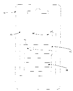
Figure 1 illustrates a front view of a product packaging portion that includes
a
coupling interface matching system in accordance with the invention;
Figure 2 illustrates a rear view of the product packaging portion of Figure 1;
and
Figure 3 is an exploded view illustrating a spent part coupling interface and
the
product packaging portion of Figure 1.
DETAILED DESCRIPTION
The present invention will now be discussed with reference to illustrations of
an
embodiment of a replacement part coupling interface matching system ("matching
system"). The illustrated matching system is for matching the plug of a spent
cordless
phone battery with a replacement phone battery plug. However, the invention is
equally
applicable to other replacement parts which include a coupling interface that
varies
between replacement parts of the same kind. Additionally, the term
"replacement part,"
as used herein, is not strictly limited to kind-for-kind replacements, but
includes
optional, "add-on" parts as well. For example, the invention is applicable to
cellular
telephone charging cords which include a coupling interface that is unique to
the cellular
telephone. By way of further example, the invention is also applicable to
replacement
headlights for automobiles. Other applications will be apparent.
Cordless telephone systems, of the type used with conventional land-based
3

CA 02327848 2000-12-07
telephone lines, normally consist of a base unit and a self contained,
detachable, handset
unit. Power for the handset unit is supplied internally, typically by
rechargeable, nickel
cadmium (NiCd) battery packs. After several charging cycles, the battery packs
in the
handsets will eventually lose their recharging capacity and hence should be
replaced.
Battery pack replacement for cordless telephones is particularly challenging
because different cordless telephone models generally use battery packs that
are similar
in appearance, but are not functionally interchangeable. Accordingly, a
consumer may
select what appears to be a con ect replacement battery from the display rack
in a store,
only to later discover that it is not compatible with his or her phone. This
problem is
currently addressed by including battery specifications and illustrations
ofthe plug type
on the product information card. However, the specification data and plug type
illustrations do not facilitate a positive identification of the correct
battery. There are
several comparison steps taken by the consumer which may introduce an
erroneous
selection.
An embodiment of a replacement battery matching system 10 is illustrated in
Figures 1 and 2. The matching system 10 includes a backing card 20, a
transparent
bubble portion 40, an opening for hanging the blister pack on a display rack,
and a plug
matching portion 60. An area 30 within the bubble portion 40 is adapted to
hold a
replacement battery.
4

CA 02327848 2000-12-07
In a preferred embodiment, the backing card 20 is substantially planer so as
to
provide a suitable support surface for the plug matching portion 60.
Accordingly, the
packaging need not include a larger substantially planer portion than the one
needed so
as to accommodate the plug matching portion 60. Thus, in a preferred
embodiment, the
plug matching portion 60 is an opening cut into the body of the backing card
and
enclosing blister pack. In an alternate embodiment, the substantially planer
portion is
a small tab, which includes the plug matching portion 60, and is rigidly
affixed to the
bubble portion 40.
The matching system 10 facilitates the identification of a proper replacement
battery by providing a backing card 20 that incorporates a "plug matching"
portion 60.
The plug matching portion 60 is adapted to mate with the plug of the
replacement
battery inside the bubble portion 40.
In one embodiment, the plug matching portion 60 is an opening that matches a
cross section of the plug. In the case of a mufti-prong plug, such as an
automobile
headlight, the opening may comprise a plurality of openings configure 4 to
match the
prongs of the plug. In another embodiment, the plug matching portion is a
dummy
coupling plug that is adapted to couple to the battery plug. For example, the
plug
matching portion may include the exterior molding for a female battery
connector plug
or a male battery connector plug.
5

CA 02327848 2000-12-07
One important feature of the invention is that the plug matching portion can
be
accessed without opening the packaging. Thus, the invention alleviates the
need to
return products to the store or complication inherent in returning open
packages.
Figure 3 illustrates the operation of the matching system of Figure 1. In
operation, the matching system is employed by a customer or a salesperson to
correctly
select a replacement part. For example, the customer may bring a spent battery
80 to
the store. The spent battery preferably includes a cable portion 90 and a plug
70. To
verify a that the battery inside the package has the same coupling interface
as the part
it is replacing, the consumer attempts to insert the spent battery plug 70
into the plug
matching portion 60. If the plug 70 substantially fits the plug matching
portion 60, the
consumer has increased confidence that the correct battery plug type has been
selected.
On the other hand, if the plug 70 does not properly fit the plug matching the
customer
can either seek the assistance of a salesperson or select a different part.
Although the present invention was discussed in terms of certain preferred
embodiments, the description is not limited to such embodiments: Rather, the
invention
includes other embodiments including those apparent to a person of ordinary
skill in the
art. Thus, the scope of the invention should not be limited by the preceding
description
but should be ascertained by reference to the claims that follow.
6

Representative Drawing
A single figure which represents the drawing illustrating the invention.
Administrative Status

2024-08-01:As part of the Next Generation Patents (NGP) transition, the Canadian Patents Database (CPD) now contains a more detailed Event History, which replicates the Event Log of our new back-office solution.

Please note that "Inactive:" events refers to events no longer in use in our new back-office solution.

For a clearer understanding of the status of the application/patent presented on this page, the site Disclaimer , as well as the definitions for Patent , Event History , Maintenance Fee  and Payment History  should be consulted.

Event History

Description Date
Inactive: IPC from MCD 2006-03-12
Application Not Reinstated by Deadline 2006-01-26
Inactive: Dead - No reply to s.30(2) Rules requisition 2006-01-26
Deemed Abandoned - Failure to Respond to Maintenance Fee Notice 2005-12-07
Inactive: Abandoned - No reply to s.30(2) Rules requisition 2005-01-26
Inactive: S.30(2) Rules - Examiner requisition 2004-07-26
Inactive: Cover page published 2001-12-31
Application Published (Open to Public Inspection) 2001-12-26
Inactive: Correspondence - Formalities 2001-09-18
Letter Sent 2001-03-01
Inactive: First IPC assigned 2001-02-26
Inactive: IPC assigned 2001-02-26
Request for Examination Received 2001-01-30
Request for Examination Requirements Determined Compliant 2001-01-30
All Requirements for Examination Determined Compliant 2001-01-30
Inactive: Filing certificate - No RFE (English) 2001-01-18
Filing Requirements Determined Compliant 2001-01-18
Letter Sent 2001-01-18
Application Received - Regular National 2001-01-17

Abandonment History

Abandonment Date Reason Reinstatement Date
2005-12-07

Maintenance Fee

The last payment was received on 2004-12-02

Note : If the full payment has not been received on or before the date indicated, a further fee may be required which may be one of the following

  • the reinstatement fee;
  • the late payment fee; or
  • additional fee to reverse deemed expiry.

Please refer to the CIPO Patent Fees web page to see all current fee amounts.

Fee History

Fee Type Anniversary Year Due Date Paid Date
Registration of a document 2000-12-07
Application fee - standard 2000-12-07
Request for examination - standard 2001-01-30
MF (application, 2nd anniv.) - standard 02 2002-12-09 2002-11-29
MF (application, 3rd anniv.) - standard 03 2003-12-08 2003-11-19
MF (application, 4th anniv.) - standard 04 2004-12-07 2004-12-02
Owners on Record

Note: Records showing the ownership history in alphabetical order.

Current Owners on Record
GEMINI INDUSTRIES, INC.
Past Owners on Record
GREG LEBRON
Past Owners that do not appear in the "Owners on Record" listing will appear in other documentation within the application.
Documents

To view selected files, please enter reCAPTCHA code :


To view images, click a link in the Document Description column. To download the documents, select one or more checkboxes in the first column and then click the "Download Selected in PDF format (Zip Archive)" or the "Download Selected as Single PDF" button.

List of published and non-published patent-specific documents on the CPD .

If you have any difficulty accessing content, you can call the Client Service Centre at 1-866-997-1936 or send them an e-mail at CIPO Client Service Centre.


Document
Description 
Date
(yyyy-mm-dd) 
Number of pages   Size of Image (KB) 
Representative drawing 2001-11-30 1 4
Claims 2000-12-07 3 62
Abstract 2000-12-07 1 15
Description 2000-12-07 6 217
Drawings 2000-12-07 3 91
Drawings 2001-09-18 3 25
Cover Page 2001-12-31 1 28
Courtesy - Certificate of registration (related document(s)) 2001-01-18 1 113
Filing Certificate (English) 2001-01-18 1 164
Acknowledgement of Request for Examination 2001-03-01 1 179
Reminder of maintenance fee due 2002-08-08 1 114
Courtesy - Abandonment Letter (R30(2)) 2005-04-06 1 166
Courtesy - Abandonment Letter (Maintenance Fee) 2006-02-01 1 174
Correspondence 2001-01-18 1 18
Correspondence 2001-09-18 4 61
Fees 2002-11-29 1 41
Fees 2003-11-19 1 35
Fees 2004-12-02 1 34