Note: Descriptions are shown in the official language in which they were submitted.
CA 02328985 2000-10-16
WO 99/54783 PGT/US99/01222
1
LINEAR AvRRAY EYE TRACKER
BACKGROOND OF THE INVENTION
1. Field of the Invention
The present invention is generally concerned with
ophthalmic instruments and surgery, and more particularly
relates to systems, methods, and apparatus for sensing and/or
tracking the position of a human eye. The present invention
is particularly useful for tracking the position of the eye
during laser eye surgery, such as photorefractive keratectomy
(PRK), phototherapeutic keratectomy (PTK), laser in situ
keratomileusis (LASIK), or the like. In an exemplary
embodiment, the present invention is incorporated into a laser
ablation system to modify the distribution of laser energy
directed at the cornea based on the sensed position of the eye
during the laser ablation procedure.
The ability to track or follow the movement of a
patient's tissue is recognized as a highly desirable feature,
particularly for use in laser delivery systems designed to
effect precision surgery in delicate ocular tissue. The eye
movements to be tracked include not only the voluntary
movements (which can be damped with specialized treatment),
but also the involuntary movements which are more difficult to
control in a living patient. In other words, even when the
patient is holding "steady" fixation on a visual target, eye
movement still occurs. This involuntary motion may compromise
the efficacy of some ocular surgical procedures, which
generally require a rate of precision. In fact, such
involuntary movements may occur despite the "total
immobilization" of the eye, as such techniques are not fully
effective in suppressing involuntary eye motion, and are also
rather uncomfortable for the patient. Automatic tracking of
the eye may alleviate any need for this uncomfortable
CA 02328985 2000-10-16
WO 99/54783 PCT/US99/01222
2
immobilization, and may offer a method for more effectively
accommodating differing types of eye motion. In other words,
augmenting surgery with real time eye tracking may improve the
accuracy and speed with which known laser eye surgery can be
performed, and may also enable new procedures to be carried
out for the first time.
A variety of techniques have been described for
tracking eye movements. One general type of eye tracking
technique has been called "optical point tracking." Optical
point trackers utilize various lens-like properties of the eye
to locate optically distinguishable locations (for example,
the first, second, third, and fourth Purkinje points).
Unfortunately, such optical point trackers implicitly assume
that the eye moves as a rigid body. As the eye actually
flexes during movement, transient relative motions of lens
structure can lead to fictitious optical point position
information. In addition, optical point tracking systems are
rather complex, and may exhibit large variability between
individuals.
Another class of eye tracking techniques generally
involve digital correlations and/or pattern recognition.
These digital techniques generally require very fast frame-
rate CCD cameras and sophisticated processing algorithms.
These methods are fundamentally digital, and they generally
involve very high frequency update rates. As tracking
frequency response is considerably slower than update
frequency in digital systems, they tend to be relatively slow.
Regardless, digital methods generally do not provide
continuous resolution, and often require extremely fast
repositioning mechanisms to leave time for complex electronic
processing within an acceptable total response time.
A recent promising technique for tracking eye
movements takes advantage of the difference in the light
scattering properties of the iris and sclera. In this
technique, light is projected on to the iris/sclera interface
or limbus, and the scattered light is detected by
photodetectors to determine the boundary location. The
CA 02328985 2000-10-16
WO 99/54783 PCT/US99/O1Z22
3
relative position of this boundary can then be monitored to
track the position of the eye.
Unfortunately, the limbus is more a transition zone
between the cornea and the sclera, rather than a sharp
boundary. As a result, techniques which rely on edge
detection may lack the desired accuracy, and may not be
capable of tracking large amplitude movements of the eye.
Another disadvantage of known limbus tracking techniques is
the relative complexity of signal processing required to
effect tracking. In other words, when the eye moves so that
the limbus is no longer in the nominal position, effecting
realignment using known tracking systems requires fairly
complex manipulations of the photodetector signal to properly
instruct the repositioning system. These complex signal
manipulations increase overall system complexity, and also
slow the system down. Work in connection with the present
invention indicates that slow tracking system response and
less than desirable accuracies may in-part be the result of
tracking system non-linearities. While adequate tracking
response may be possible using known "pin-point" limbus
trackers with accurately aligned photodetectors disposed
precisely along the edge of the iris/sclera interface,
providing and/or maintaining such alignment adds additional
system components and complexity, particularly in light of the
variability of eye geometry between differing patients.
In light of the above, it would be desirable to
provide improved eye sensing and tracking devices, systems,
and methods. It would be particularly desirable if these
enhanced techniques improved tracking response times and
sensitivity, but without significant increases in cost or
complexity of the tracking mechanism. It would be
particularly desirable to provide these enhanced capabilities
in a system which was adaptable for use in laser eye surgery
for accurately sensing and/or tracking a variety of patient
eye movements.
CA 02328985 2000-10-16
WO 99/54783 PCT/US99/OI2Z2
4
SU1~IARY OF THE INVENTION
The present invention provides improved devices,
systems, and methods for sensing, and in most cases tracking,
the position of an eye. The techniques of the present
invention generally make use of the difference in contrast
between the white of the eye or sclera and the colored iris to
derive the position of the eye. In many embodiments, linear
photodetectors having an elongate sensing area extend from the
iris to the sclera. Where the eye is positioned between a
pair of such linear photodetectors, movement of the eye from
one linear detector toward the other linear detector will
change the relative amounts of light striking each linear
detector. The amount of misalignment between the linear
detectors and the eye will be proportional to the difference
in the signal output by the detectors. Therefore, this
difference in signal between a pair of opposed linear
photodetectors provides an excellent feedback signal,
requiring only very simple amplification for use as an input
signal for a repositioning mechanism. Such simple signal
processing not only reduces the circuitry complexity and cost,
but significantly enhances the speed and accuracy of tracking.
Conveniently, pairs of coaxial linear photodetectors
can accurately sense and measure one-dimensional positioning
error of a substantially round feature such as the iris. The
tracking systems of the present invention take advantage of
this one-dimensional error measurement, together with the
significant contrast between the iris and the sclera, by
measuring total light along two coaxial bulk linear
photodetector which cross the limbus at radially opposed
positions. This arrangement can provide accurate relative
position information despite the lack of a sharp boundary at
the limbus. Providing two such pairs of bulk linear
photodetectors, each pair independently providing feedback to
a one-dimensional positioning apparatus, results in a highly
linear system giving accurate position tracking throughout a
wide range of eye motion speeds and amplitudes.
In a first aspect, the present invention provides a
system for sensing movements of an eye in a living body. The
CA 02328985 2000-10-16
WO 99/54783 PCT/US99/OI222
eye has an iris surrounded by a sclera, with a limbus
therebetween. The system comprises a first linear
photodetector having an elongate detector area. The detector
area has an inner end and an outer end, and defines an axis.
5 A second linear photodetector also has an elongate detector
area with an inner end, an outer end, and an axis. The inner
ends are alignable with the iris, while the outer ends extend
toward the sclera so that each linear detector is aligned
across the limbus. A second linear detector is radially
offset from the first linear detector relative to the aligned
iris to measure displacement of the iris from between the
first linear detector and second linear detector.
In many embodiments, the first and second linear
detectors are substantially coaxial. A processor will often
be coupled to the first and second linear detectors, the
detectors each producing a signal indicating total light
within the elongate detector area. The processor compares
these total light signals to sense when the iris moves
laterally toward one of the linear detectors and away from the
other. Such a pair of linear coaxial photodetectors are
particularly well suited for measuring movement to the eye
along the axis of the photodetector pair. By including a
second pair of linear photodetectors, the sensing system can
detect and measure any lateral movements of the eye relative
to the ocular axis. A simple and rapid tracking system can be
provided by coupling each pair of transducers to an actuation
mechanism which varies alignment between the linear
photodetector pair and the eye along the axis of the
photodetector pair.
In another aspect, the present invention provides a
tracking system for maintaining alignment between an eye and a
laser beam for use in laser eye surgery. The eye has an iris
surrounded by a sclera, and the tracking system comprises a
first pair of linear photodetectors. Each detector has an
inner end oriented toward the iris and an outer end oriented
toward the sclera. A first pair of linear detectors defines a
first movement sensing axis therebetween. The second pair of
linear photodetectors similarly defines a second movement
CA 02328985 2000-10-16
WO 99/54783 PCT/US99/01222
6
sensing axis therebetween. A processor is coupled to the
first and second pairs of detectors. The processor is adapted
to compare light signals from between the linear detectors of
each pair for sensing movement of the iris along the sensing
axis of the pair. An actuation system is coupled to the
processor. The actuation system is adapted to maintain
alignment between the linear detectors and the eye.
In a method according to the present invention, eye
positions can be sensed in a living body by illuminating an
iris and a sclera of the eye. Light from the illuminated eye
is measured with a plurality of linear photodetectors while
the detectors are oriented radially so that each detectors
extends from the iris to the sclera. The light measured at a
first detector is compared to the light measured at a second
detector to sense movement of the iris from therebetween.
In yet another aspect, the invention provides a
method for tracking an eye of a living body. The method
comprises illuminating an iris and a sclera of the eye. Light
from the illuminated eye is measured with a pair of linear
photodetectors while the linear detectors are oriented
radially. More specifically, each detector is aligned across
a limbus of the eye to extend from adjacent the iris to
adjacent the sclera. An error signal is generated from a
difference between light measured by the detectors of the
pair. The iris is then realigned between the detectors using
the error signal. Advantageously, such an error signal can
provide an independent one-dimensional feedback signal. This
highly linear one-dimensional signal is particularly well
suited for manipulation and amplification to provide a
repositioning signal for a repositioning mechanism, thereby
providing a simple, fast, and accurate feedback control system
which is governed by one-dimensional convolution integral.
BRIEF DESCRIPTION OF THE DRAWINGS
Fig. 1 schematically illustrates the tracking system
of the present invention, in which lateral movements of the
eye are measured from the difference in light intensity
CA 02328985 2000-10-16
WO 99/54?83 PCT/US99/01222
7
measured between two pairs of bulk linear photodetectors along
two independent measurement/repositioning axes.
Fig. lA schematically illustrates a photodiode
structure for use in the system of Fig. 1.
Fig. 2 is a schematic side-view of a laser surgery
system including the tracking system of Fig. 1 for one of the
two independent axes.
Figs. 3A and 3B illustrate a method for sensing
lateral eye movements in one-dimension using a pair of coaxial
linear bulk photodetectors.
Fig. 4 schematically illustrates an alternative eye
movement sensing system including two linear photodiode
arrays, thereby providing absolute limbus location sensing as
well as relative translation from the sum of linear array
outputs.
Fig. 5 schematically illustrates a method for
measuring velocities using linear photodetectors.
DESCRIPTION OF THE PREFERRED EMBODIMENT
The present invention is directed to devices,
methods, and systems for sensing and/or tracking the position
of an eye in a living body. The techniques of the present
invention generally make use of the contrast of a recognizable
large scale boundary of the eye, such as at the cornea/sclera
interface (the limbus). The sensing or tracking systems often
determine the location and velocity of these boundaries
without having to resort to digital sampling techniques. In a
preferred aspect, the cornea/sclera interface position is
tracked relative to a specific axis using a pair of elongate
bulk photodetectors. By arranging these elongate detectors so
that each has one end within the relatively dark iris, and one
end extending beyond the limbus to the white sclera, the
relative position of the limbus (and the iris) can be
determined.
The present invention generally makes use of linear
bulk photodetectors. These photodetectors are capable of
providing a signal which indicates a total illumination along
CA 02328985 2000-10-16
WO 99/54783 PCT/US99/01222
8
an elongate light sensing area. To take advantage of the
significant contrast between the sclera and iris, without
having to pinpoint and track a position of a boundary between
these large, high contrast structures, the Light sensing area
will extend across (and beyond) the limbus.
The devices, systems, and methods of the present
invention may find application in a variety of settings. For
example, the eye position sensing techniques of the present
invention may be used for clinical or academic studies of both
saccadic and voluntary eye movements. These techniques and
structures will find their most immediate application in
augmenting laser eye surgery. More specifically, the tracking
systems of the present invention may be used to maintain
alignment between a therapeutic laser beam and an eye to
enhance the accuracy of laser eye surgery directed at
reshaping of the cornea. Alternatively, the pairs of linear
photodetectors may be used without tracking to interrupt such
a laser photoablation procedure whenever the eye moves beyond
an acceptable aligned range. Regardless, the paired linear
bulk photodetectors of the sensing/tracking system of the
present invention offer enhanced system response times over a
broad range of eye motion amplitudes.
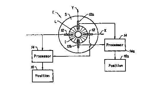
Referring now to Fig. 1, a tracking system 10 is
used to track lateral movements of an eye E using a series of
linear bulk photodetectors 12. Detectors 12 are arranged in
coaxial pairs, with signals from the detectors compared by a
processor 14, the processor manipulating the detector signals
to direct a repositioning mechanism 16. Repositioning system
16 will then alter alignment between eye E and detectors 12
based on the signals from the processor.
Detectors 12 each have an elongate light sensing
area, the detectors generally being radially oriented. While
detectors 12 are illustrated superimposed on eye E in the
schematic of Fig. 1, it should be understood that the
detectors will often sense a position of eye E based on an
image of the eye. Hence, descriptions of the relative
positions of detectors 12 relative to the structures and
features of eye E will often, in practice, be carried out
CA 02328985 2000-10-16
WO 99/54783 PCT/US99/01222
9
using an image of the eye. For example, eye E includes a
sclera S and an iris I with a limbus L defining the border
therebetween. Photodiodes 12 are disposed "across" limbus L
to extend from iris I to sclera S, so that each bulk detector
measures light from both the substantially white, relatively
bright sclera, and from the much darker iris. However, it
should be understood that the detector structures may be at
some distance from the eye, so that the detectors actually
extend across an image of the eye. The image of the eye will
often be produced by an optical train between the eye and the
detectors. Alternatively, the photodiodes may be mounted on a
spectacle frame near the eye and oriented directly across the
sclera/iris interface.
Linear detectors 12 will typically comprise elongate
silicon photodiodes. Silicon photodiodes typically have time
constants of tens of picoseconds. As a result, the sampling
rate will often be limited by the exposure time. More
specifically, sampling rate is inversely related to exposure
time, so that the shorter the exposer time, the higher the
sampling rate.
The spectral response for silicon photodiodes
centers in the near infrared (typically around about 750 ~Cm).
These detectors are generally sensitive to light throughout a
fairly broad spectrum, providing at least about fifty percent
sensitivity throughout the range from 450 ~,m to 950 ~Cm. The
preferred illumination source will ideally include a
significant output within this range when silicon photodiode
detectors are used. Alternatively, detectors 12 may sense
light anywhere throughout the range of about 350 to 1100 ~,m,
either by making use of lower sensitivities, using alternative
diode structures, or the like.
An exemplary silicon photodiode structure is
illustrated in Fig. lA. Linear detector 12 includes an array
of detector elements 13. Detector elements 13 are wider
laterally (relative to the detector axis) than their axial
length. This increases the overall detection area while
preserving axial resolution. Hence, this structure provides
CA 02328985 2000-10-16
WO 99/54783 PCT/US99/01222
increased axial signal to noise performance at the expense of
resolution along an unused transverse sensing orientation.
Processors 14 will generally compare the signals
produced by a pair of opposed detectors 12. The detectors
5 will be long enough to measure lateral movements of eye E
along one dimension, and will be much longer than their width.
Processor 14a measures a position of iris I of eye E along an
axis Y by comparing a signal produced by a first detector 12a
to the signal produced by a second detector 12b. When eye E
10 moves upward, the amount of sclera S adjacent first detector
12a will decrease, while the amount of the sclera adjacent the
second detector 12b will increase. Conversely, the darker
iris will increasingly be exposed to first detector 12a, and
will have a decreasing exposure to second detector 12b. As a
result, the total illumination signal produced by first
detector 12a will decrease, while the signal produced by the
second detector 12b will increase. By comparing these
signals, processor 14a can sense that eye E has moved in the
positive Y direction, and can also measure the amount and
velocity of that movement based on the quantitative difference
in signals, and by the rate of change of this difference,
respectively.
Processors 14 may optionally comprise relatively
simple analog circuits, or may alternatively include one or
more analog-to-digital convertors coupled to a digital
processor. Use of an analog circuit may be preferred to
enhance system response, particularly when repositioning
mechanism 16 is adapted for use with an analog input signal.
Repositioning mechanism 16 will generally effect
realignment between detectors 12 and eye E based on the
positioning signal from processor 14. To separate the one-
dimensional feedback loops along X and Y axes as illustrated
in Fig. l, positioning mechanism 16a attached to processor 14a
will preferably affect only the alignment along axis Y. A
variety of mechanisms may be used to provide such one-
dimensional repositioning. For example, repositioning
mechanism 16a may translate the spectacle frame supporting
detectors 12 along the axis. Alternatively, repositioning
CA 02328985 2000-10-16
WO 99/54783 PCTNS99/01222
11
mechanism 16 may pivot a mirror to effect realignment between
an image of eye E and detectors 12. Where processor 14
provides an analog signal to repositioning mechanism 16, the
repositioning mechanism will often include an analog
electromechanical actuator such as a voice coil motor, or the
like. Where processor 14 provides a digital signal to the
repositioning mechanism, digital electromechanical actuators,
such as stepper motors, may instead be used.
Fig. 2 illustrates a system 20 for selectively
photoablating corneal tissues so as to effect reshaping of the
cornea. Laser ablation system 20 incorporates the elements of
tracking system 10 of Fig. 1. Laser ablation system 20 also
includes a laser 22 which produces a laser beam 24. Laser
beam 24 and linear detectors 12 are aligned relative to eye E
by repositioning mechanism 16. In this embodiment,
repositioning mechanism 16 makes use of a pivoting mirror 26
to alter a position of an image of eye E upon linear detectors
12. In other words, a limbus image L' superimposed on
detectors 12 is aligned relative to the detectors by pivoting
mirror 26 as shown. An optical train (not shown) may be
included in positioning system 16 to image the eye, and to
direct laser beam 24.
Imaging and sensing can be enhanced by illuminating
eye E with light energy appropriate for measurement by
detectors 12, as described above. Such illumination can be
provided by oblique illuminators 28. The portions of tracking
system illustrated in Fig. 2 will generally maintain alignment
between laser beam 24 and eye E only along axis X. A second
pair of detectors 12 coupled to an independent processor 14
and a substantially independent repositioning mechanism 16 can
be used to track the eye during movements into and out of the
plane of the drawing. An improved tracking system according
to the invention using repositioning mirrors might be
incorporated into a laser eye surgery system commercially
available from VISX, Incorporated of Santa Clara, California,
under the trademark STAR'''"'.
A change in relative signals from linear detectors
12 can be understood with reference to Figs. 3A and 3B. Each
CA 02328985 2000-10-16
WO 99/54783 PCT/US99/01222
12
of detectors 12 defines an elongate light sensing area 30
having an inner end 32 and an outer end 34. Inner ends 32 are
generally aligned with iris I, while outer ends 34 extend out
to the surrounding sclera. As a result, detectors 12 extend
across limbus L and will sense a light in part from the
relatively dark iris I, and in part from the significantly
brighter sclera.
Detectors 12 will generally operate in pairs to
sense the relative position of iris I. First detector 12a and
second detector 12b are aligned coaxially along axis X.
Qualitatively, when iris I moves to the right relative to
detectors 12 (as illustrated in Fig. 3A, or when moving from
point B to point C in Fig. 3H), more of the bright sclera is
exposed to first detector 12a, thereby increasing its output
signal. Conversely, more of second detector 12b is blanketed
by the dark iris, thereby decreasing its signal. However,
where iris I moves perpendicularly relative to axis X (such as
from point A to point B as illustrated in Fig. 3B), the signal
strength from both first detector 12a and second detector 12b
will decrease by about the same amount. Hence, by comparing
the signal from first detector 12a relative to the signal from
second detector 12b, a pair of detectors can be used to
indicate movement of iris I along axis X independently of any
motion along a transverse axis Y.
Quantitatively, the signal from second detector 12b
(and for each of the detectors) will be:
1
S = fI(X)dx
0
in which 1 is the length of second detector 12b, and I(x) is
the intensity at a position x along length 1. As an example,
Fig. 3C illustrates an intensity profile comprising a step
function with two different constant values: an arbitrary low
intensity such as I=100 within iris I, and an arbitrary high
intensity such as I=200 along the sclera. If we assume that
half the length of second detector 12b is initially aligned
CA 02328985 2000-10-16
WO 99/54783 PCT/US99/01222
13
with the iris and half is aligned with the sclera (lo = 1/2),
the signal S is then given by:
1/2 l
s = ~ I. dx+~Iadx = 2 (I1+Iz)
o va
As described above, when iris I moves toward second
detector 12b, signal S will decrease. More specifically,
where iris I moves to the right. by OI so that the limbus moves
from 1/2 to 1', the signal from second detector 12b will
decrease by:
z 1
AS = S- f hdx+ f I2dx
o r
z r
= f hdx_~I2dx
10 10
in which 1' is the new position of our theoretical limbus
along second detector 12b (1~ - to + OI), while I1 and I2 are
the intensities along the iris and sclera, respectively.
Using our constant I1 and I2 from our step function example,
we now have an intensity distribution I(x) as illustrated in
Fig. 3D, giving us a total change in signal OS as follows:
0S = (I1-I2) 01
in which (h - I2) is the contrast between the iris and the
sclera. (200 - 100 = 100 in our example).
Another way to think of the integral which gives us
the signal S from our bulk photodetector is to look at it as a
moving average of the light intensity along a slit.
Advantageously, the tracking system compares the average light
from slits which extend well beyond the gradual transition in
contrast which actually occurs at limbus L, as illustrated by
CA 02328985 2000-10-16
WO 99/54783 PCT/US99/01222
14
the broken line in Figs. 3C and 3D. In contrast to the
irregular variations along this transition, the average
illumination through the opposed slits will vary smoothly when
iris I moves relative to the detectors. For relatively small
changes in alignment and relatively small contrast variations,
the displacement is proportional to the change in signal.
Velocity measurements can be made quite accurately
by monitoring a rate of change of the position along the X
axis. The accuracy for such velocity measurements is a
function of the ratio between the contrast and the noise from
detectors 12. More specifically, velocities may be calculated
as a rate of change of an edge signal 35, although the edge
need not be sharp. A moment integral can be obtained from
signal samples taken before a time interval and after the time
interval. The difference in signal divided by the time
interval will indicate velocity.
Good performance signal to noise (S/N) performance
will provide a more accurate moment, thereby giving better
velocity measurements. The better the S/N performance, the
less likely a noise spike will be inadvertently interpreted as
a movement of the eye. In other words, if there is too much
noise, velocity measurements become difficult because the edge
position becomes ill defined, and the moment will have a large
standard error. Averaging of the data can help to improve the
S/N performance to more accurately calculate a fixed or slow
moving edge, but sequential signal averaging may reduce the
maximum measurable velocity.
Referring now to Fig. 4, an alternative sensing
system 30 uses a pair of linear array photodiodes 32a, 32b.
Such a linear array can give additional spacial information.
Specifically, the digital nature of a linear array provides
absolute edge location, rather than just relative measurements
of the iris position. The accuracy of this absolute position
sensing system will depend on the pixel dimensions of the
linear array, as well as on classical optical constraints such
as field of view, magnification, and the like.
The spacial information provided by linear arrays 32
is essentially the same as a single line of video.
CA 02328985 2000-10-16
WO 99/54783 PCT/US99/01222
Advantageously, a single line pixel array avoids the
limitations of standard video input, including the slow CCD
refresh rates, and the like. This may provide sampling rates
significantly higher than the typical video refresh rates of
5 30 or 60 Hz, and preferably as high or higher than high video
refresh rates of about 120 Hz.
Currently available linear array photo diodes often
include arrays of 256, 512, or 1,024 pixels. For a view field
of 25 mm, the resolution of a 1,024 linear array photodiode is
10 24 ~,m. The dimension of each array element is about 2.5 ~m
wide by 25 ~m long along the axis of the array, thereby
providing quite good axial resolution. The wider dimension
generally helps enhance sensitivity of the array.
Advantageously, the output from each element of
15 linear arrays 32 can be summed to provide the same information
available from a bulk detector, as described above.
Therefore, so long as first array 32a and second array 32b
cross limbus L at radially separated positions, the sum of the
signals from these two linear arrays can be compared to
determine the relative position of iris I along axis X between
the arrays. In other words, in addition to the absolute edge
position information provided by the array, pairs of linear
photodiode arrays can be used as bulk photodetectors to
measure the relative movement of iris I from a midline M
bifurcating the arrays. Therefore, multiple pairs of arrays
may be used in some applications.
The sensing and tracking systems of the present
invention have generally been described with reference to
movement along a single axis between pairs of detectors. As
described with reference to Fig. 1, these systems will often
include a second pair of detectors for sensing and/or tracking
movements transverse to the sensing axis of the first pair.
While such tracking may be enhanced by maintaining an
orthogonal relationship between these two sensing axes,
eyelids or other obstructions may be avoided by placing the
pairs at oblique angles.
While the present invention has been described in
some detail, by way of illustration and for clarity of
CA 02328985 2000-10-16
WO 99/54783 PCTNS99/01222
16
understanding, a variety of changes, modifications, and
adaptations will be obvious to those who skill in the art.
For example, horizontal and vertical movements of the eye may
be tracked by selectively comparing signals from three linear
photodiodes, in which a processor treats each of the
photodiodes as an element of two pairs. Hence, the scope of
the present invention is limited solely by the appended
claims.